|
ZW3D is
similar to the Solidworks clones with four distinct advantages:
- Multi-Object Environment - Parts
and assemblies in a single file
- Primitive Shapes - Using
primitive shape increase productivity 30%
- Integrated Drawing -
Solves many of the PDM and PLM problems
- Usable Robust Integrated Direct Edit
Functionality
We have the native ZW3D and STEP File Available here for download
Note: IronCAD native files must be copied
to the same folder.
3D Modeling is the basis for our
engineering. That is the only place where productivity is paramount.
You can have all the PLM/MBE gurus debating data management, but it
does not add one smidgeon of productivity to the design process.
Top down or In-Context modeling is the most productive
feature of 3D CAD. Most systems tout this but each part is still and
external part. We are talking about a single model of multi-object
design environment. Both of the systems we represent offer this as
the "normal" design process. Thereby increasing your productivity 20
to 30%.
In these exercises I not only focus on modeling techniques, but
also on much more productive systems to do our designs. I hope you
enjoy them and learn something. If you are in management, understand
that all 3D CAD systems are not the same. Cutting your engineering
costs is very simple. Even your legacy data is not a problem. Please
feel free to give me a call. There are millions of man hours wasted
every day with poor modeling techniques and ineffective 3D CAD
systems that cost a fortune. Productive 3D CAD systems do not have
to be expensive.
Joe Brouwer
206-842-0360
I am
doing the below assembly for an exercise showing my modeling
techniques and, of course, our superior 3D CAD
solutions.
3D CAD Modeling Techniques
I saw the following video challenges on linkedin and thought I would
give it a try on IronCAD. I got a great response and decided to do
it in ZW3D. I was very familiar with the parts and it was a bit
easier.
ZW3D vs Fusion 360
These exercises started out to show the benefits of
ZW3D over Fusion 360, but
quickly turned into a study of modeling techniques. Take a look at all of
them, they will open your eyes to a much different and more productive way of
modeling. It really has more to do with modeling technique than it has to do
with the 3D CAD systems. I have found that I do 3D modeling as compared to
the conventional 2D sketching. Of course, having a more productive 3D CAD
system doesn't hurt.
ZW3D is very similar to the Pro/e
clones with a few small differences. It is very easy for those users
to get up and running with ZW3D. It has a few operation that
are a bit more streamlined. The benefits over the other systems
are the multi-object environment (top down design) with the integrated drawing. You can
do parts, assemblies and drawings in one file.
These exercises were incredibly
popular and I thought I would follow up by showing more examples of
this 3D modeling technique.
We will be doing a
couple of parts each weekend in both IronCAD and ZW3D. I hope you
enjoy these exercises and hopefully they may lead to increasing your
productivity.
Please review lesson one:
3D Modeling Techniques ZW3D Lesson One
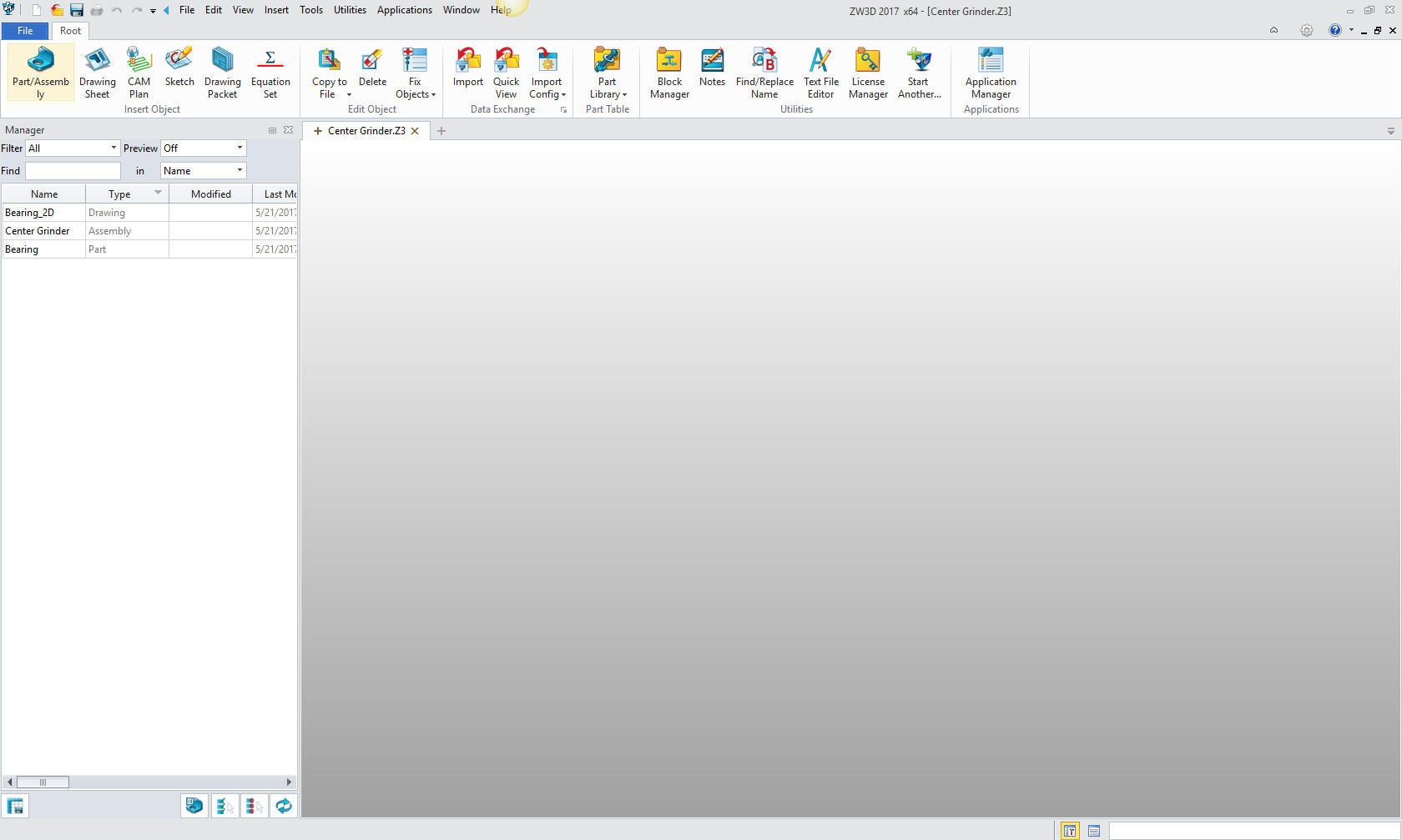
We will bring up the Center Grinder file:
Since we created this file as a multi-object the ZW3D Manager
automatically comes up. It shows the assembly, the bearing and the
bearing drawing.
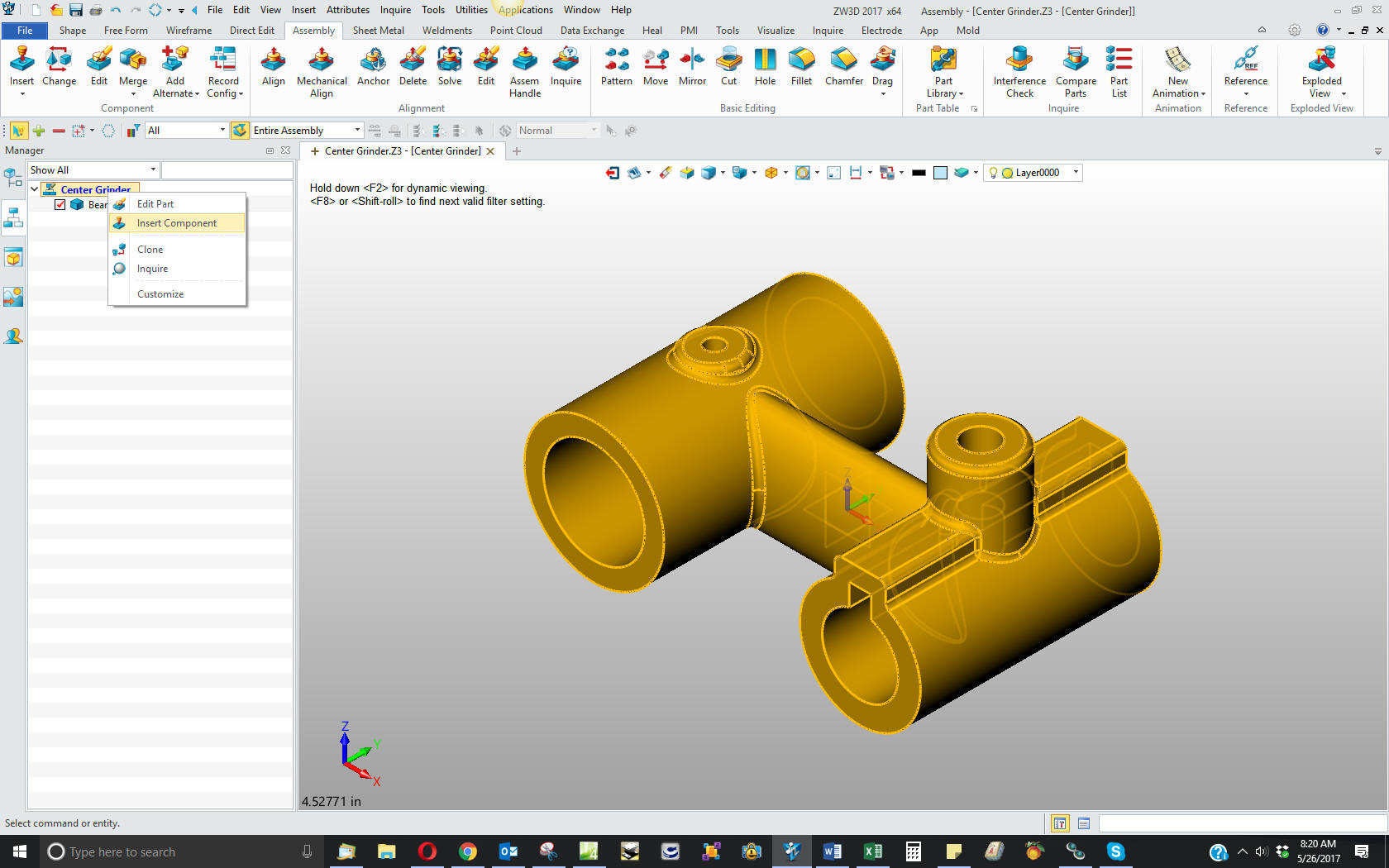
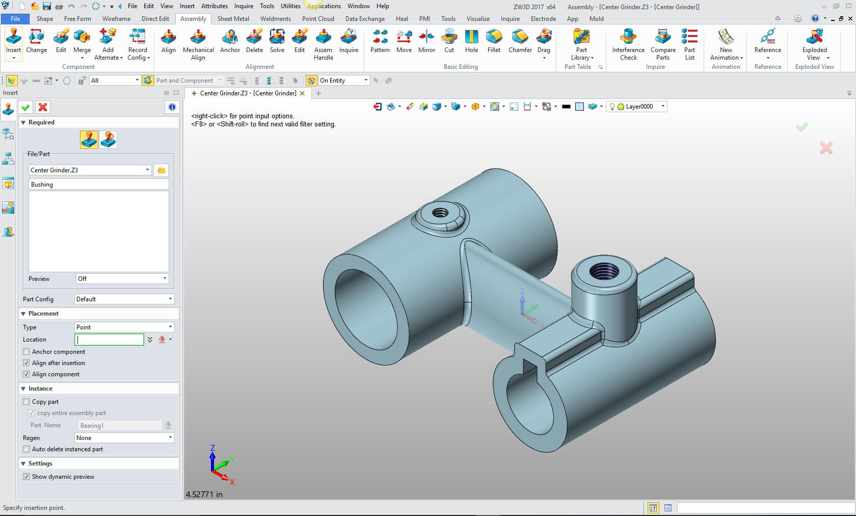
We will select the
center grinder assembly and we will see the existing parts. We will
right click on the Center Grinder assembly and select "insert
component". Again I want to reiterate this is not a true single
model environment. Each part is still like a external reference
except that it resides in the same file.
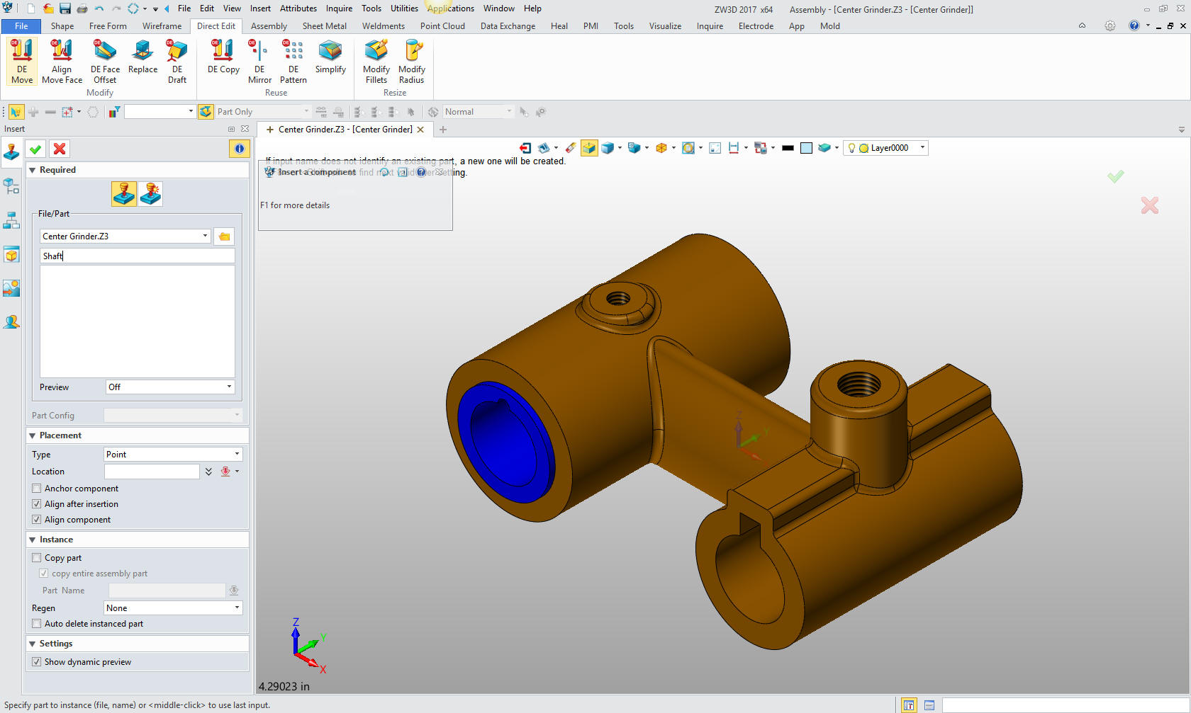
Now we
insert the Bushing as a new part.
Note: ZW3D's Multi-Object
top down design is an incredible time saver. Especially for the
individual design. Which is most of us. Even in large companies a
designer is given a sub-assembly to develop.
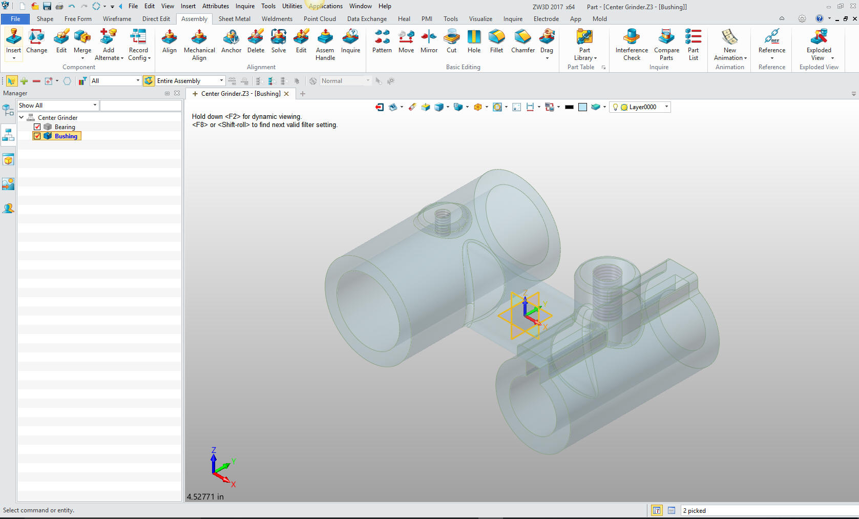
This
step automatically puts us in the "edit part" mode that shows the
other parts as ghosted. They are available for reference as you
will see. We also have the "open part" mode which has only the
single part available. You can make these external individual parts
as required.
Note: I have surprisingly found that ZW3D is a
superior top down design program. I have worked with many top down
design packages (There are only 4 that I know of) and ZW3D is
incredibly productive.
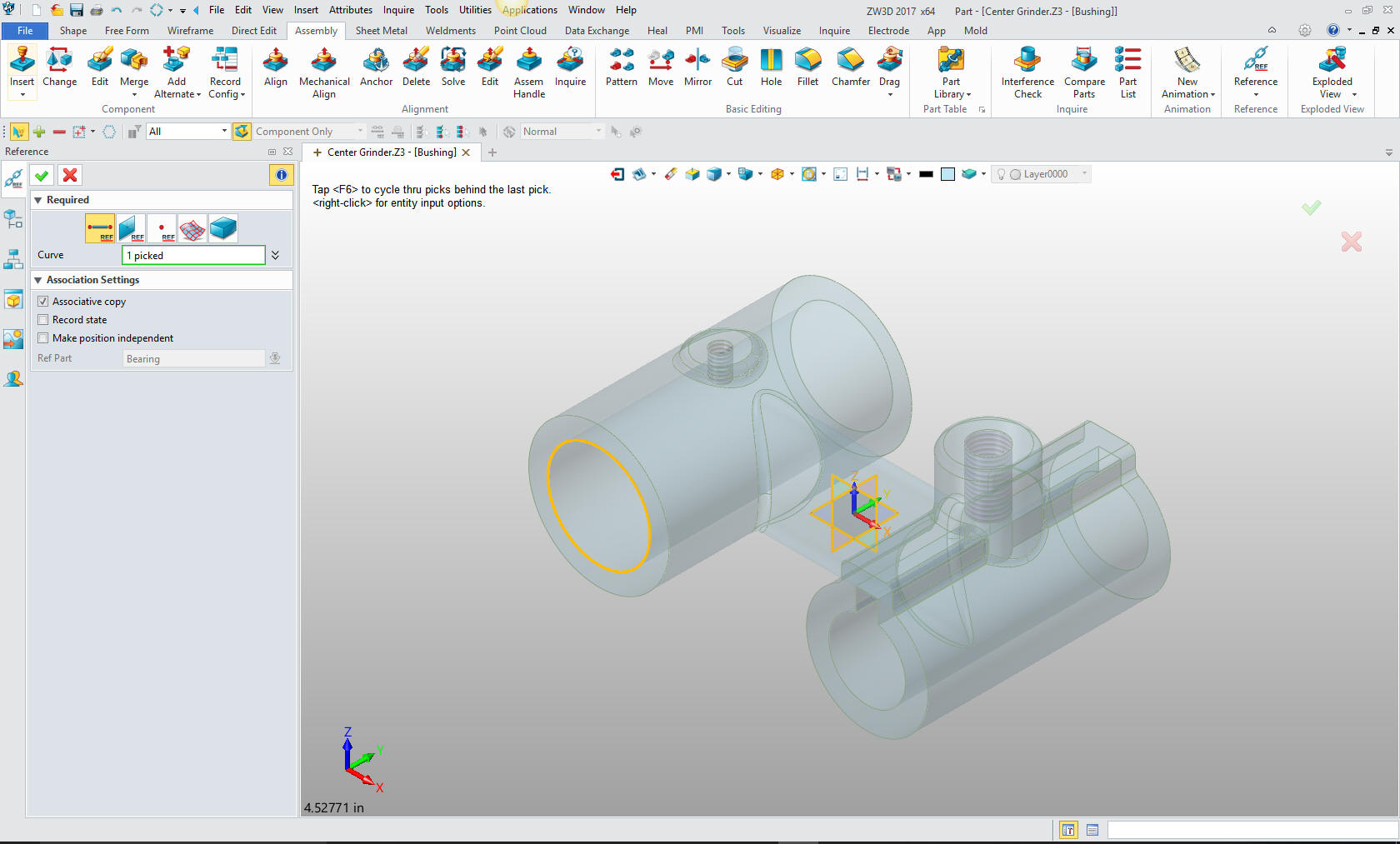
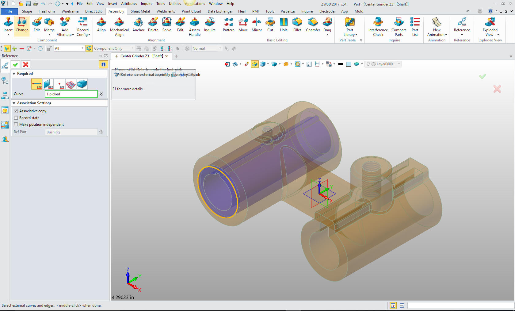
Now
will will begin on modeling the bushing. We are going to design in
top down or in context design. We will go to the assembly menu and
reference an edge.
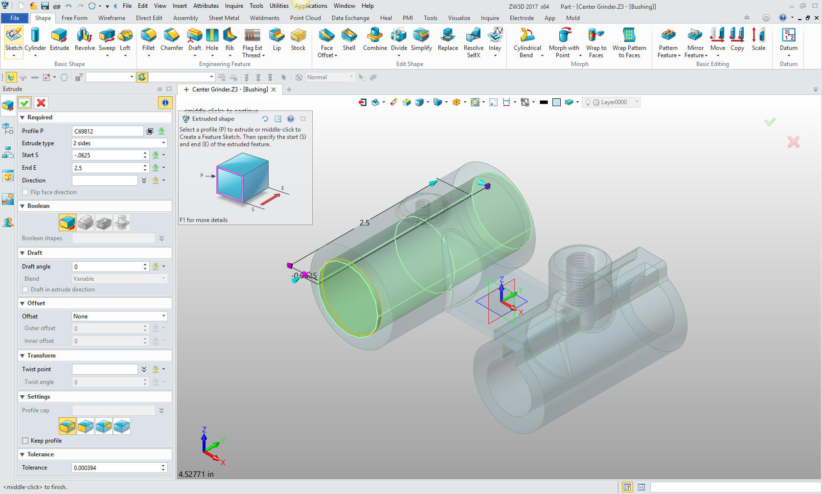
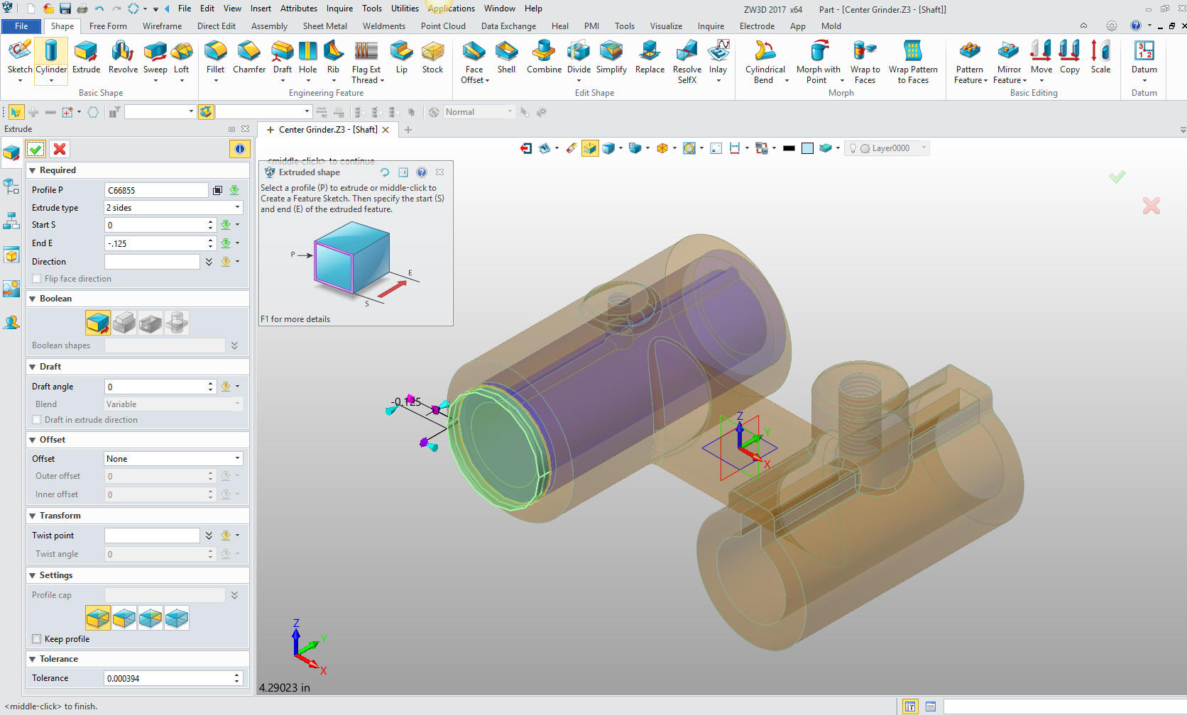
Now we
will go the the shape mode and select extrude. We just select the
reference circle, no sketch required, size it in the assembly. Very,
very productive and simple.
Note: I have to admit there is
only one other program that has this feature and I have tens of
thousands of hours on it. This is by far one of the most productive
modeling features available. No sketch, no setup at all. Pure
modeling.
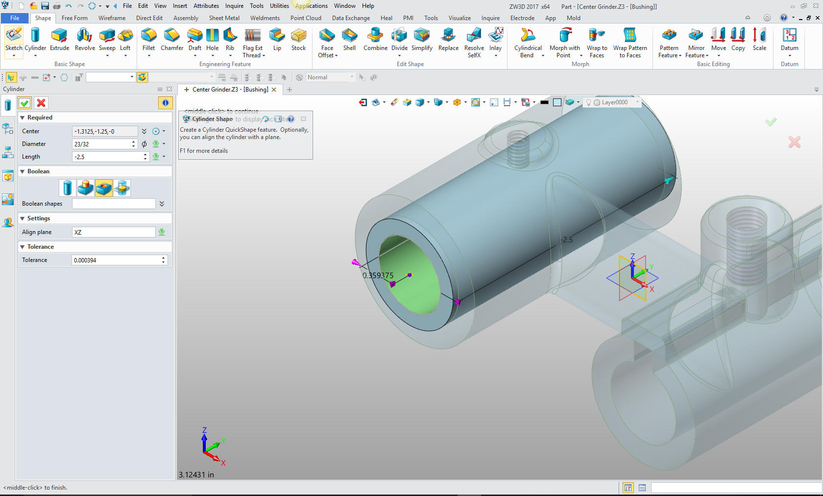
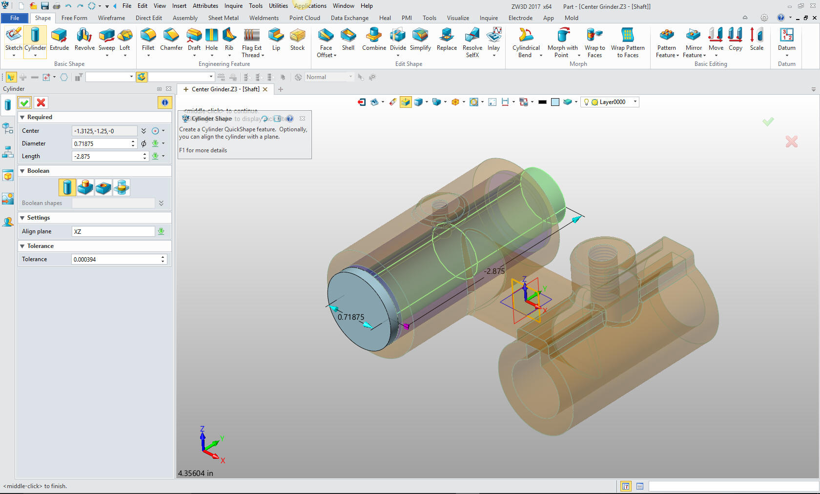
That
being done we now create the hole by inserting a primitive cylinder
and setting it as subtract. We will select the center of the
bushing, set the alignment and size it. (We have the tool tips
shown. You can go to help and it will show you how it is used)
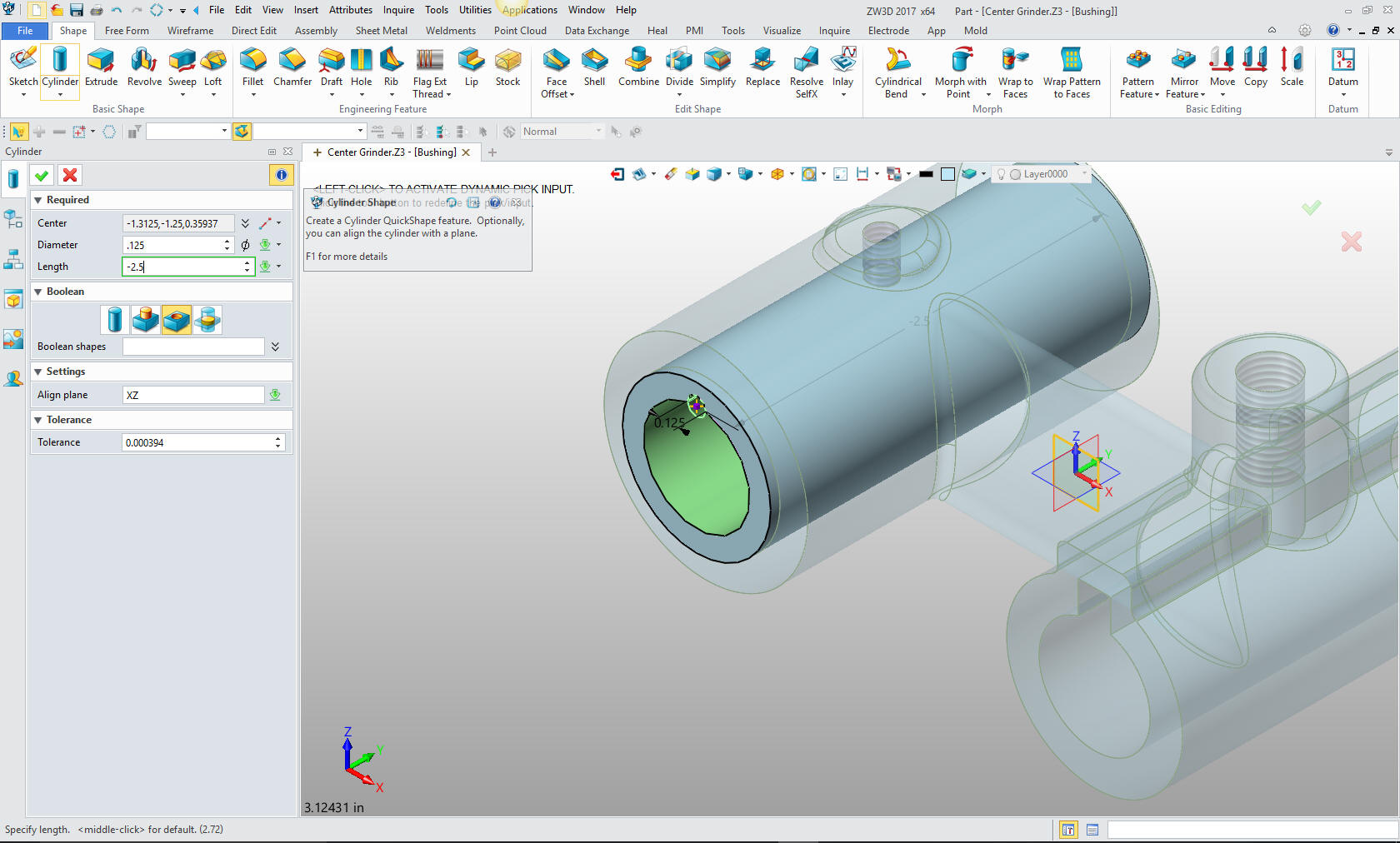
Now for the oil groove. We again insert a primitive cylinder and set
it to subtract, we offset it from the center of the hole to located it and
size it.
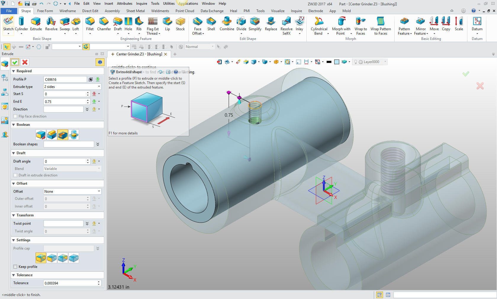
We now
locate the oil hole on top by again going to the assembly menu and
referencing the top circle which shows purple.
We
again go the the shape menu and select extrude, pick the circle and
size it.
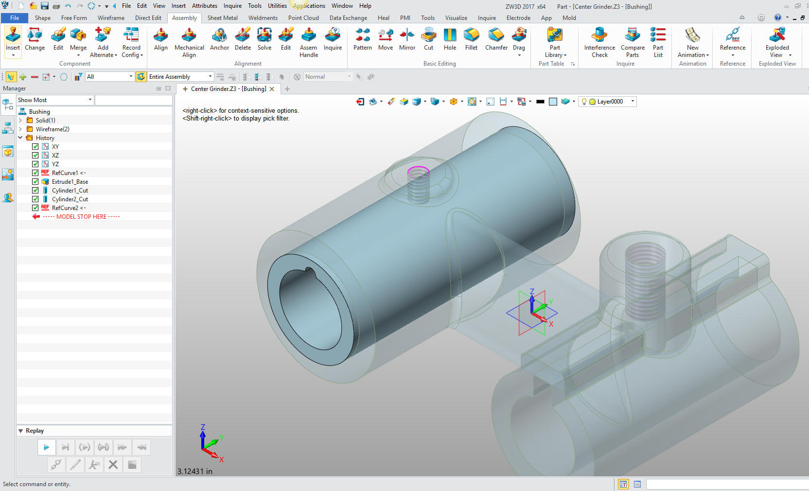
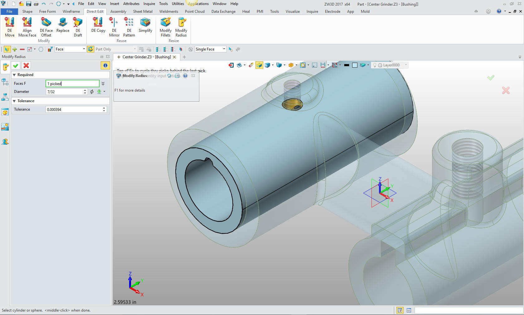
Here
is a step many of you will not be familiar. We will go the the
direct edit menu and directly edit the hole by using the modify
radius command to the correct size, 7/32. This is a very, very
productive function when working top down design. Most would have to
create a sketch then set the diameter. But this is one very simple
step.
We are now done with the part. I will select the Center Grinder
assembly for our next step. We now insert a new component: The
Sleeve. You can see I have change colors for clarity.
I will
select the assembly menu and again reference the mating edge to
start the Sleeve.
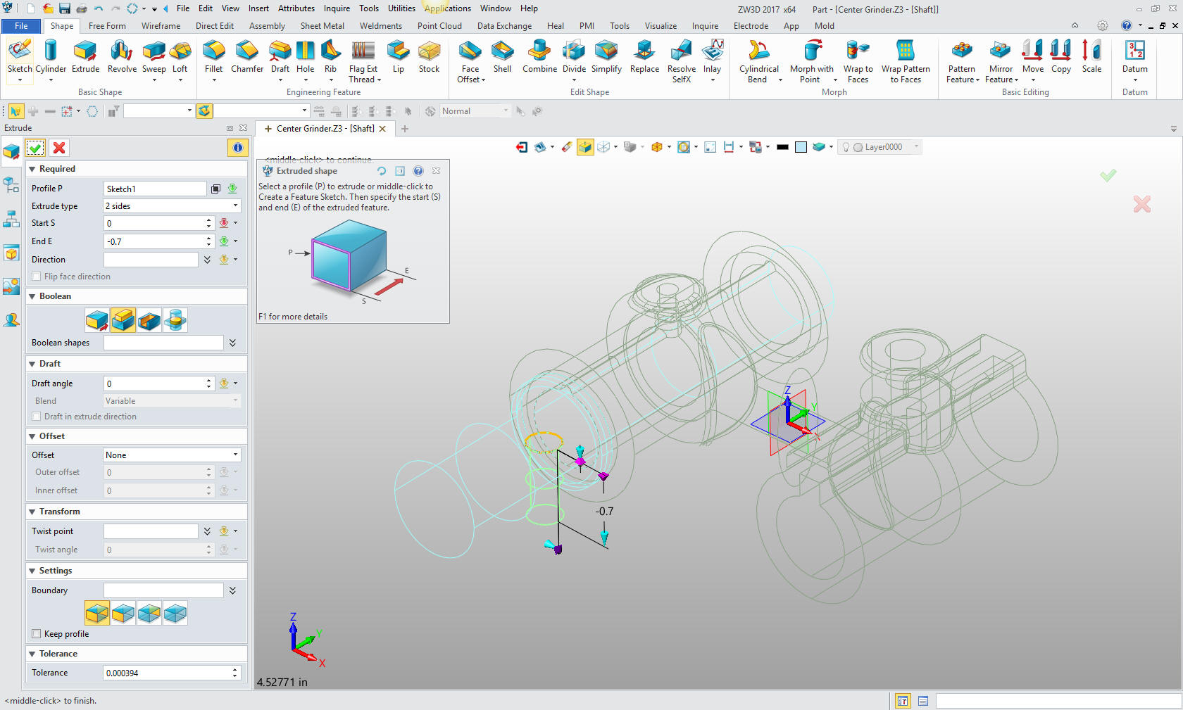
I move
the shape menu and select extrude and select the circle and size it.
Again no sketching involved. Incredibly productive.
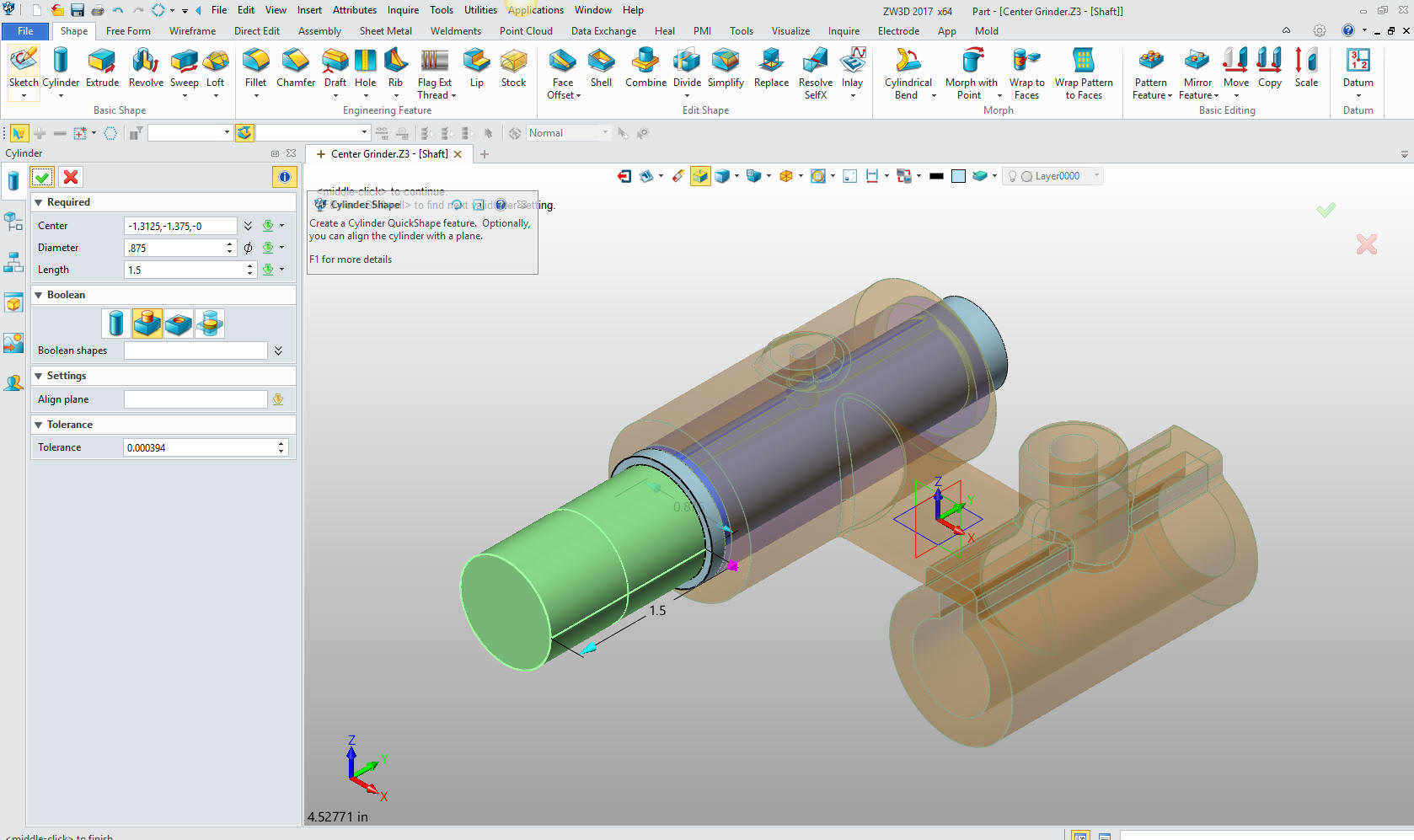
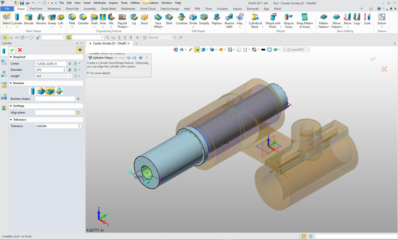
For
the back shaft we just create another primitive, center on the edge
of the existing cylinder on the back face, so it can easily be
sized.
Now
for the front shaft. Again we insert a primitive cylinder on the
center of the face of the existing cylinder, align it and size it.
Can it be more simple?
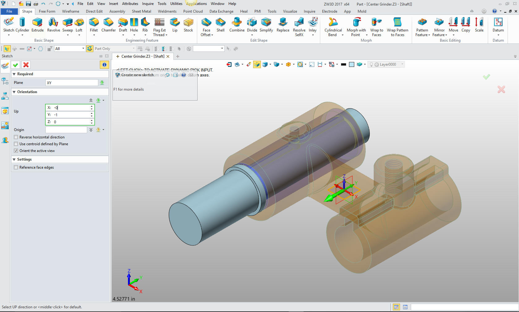
Now we
have the hole on the bottom. We will sketch this feature since it is
not located by the center of the hole. We select the XY plane and
set the up directs: negative Y
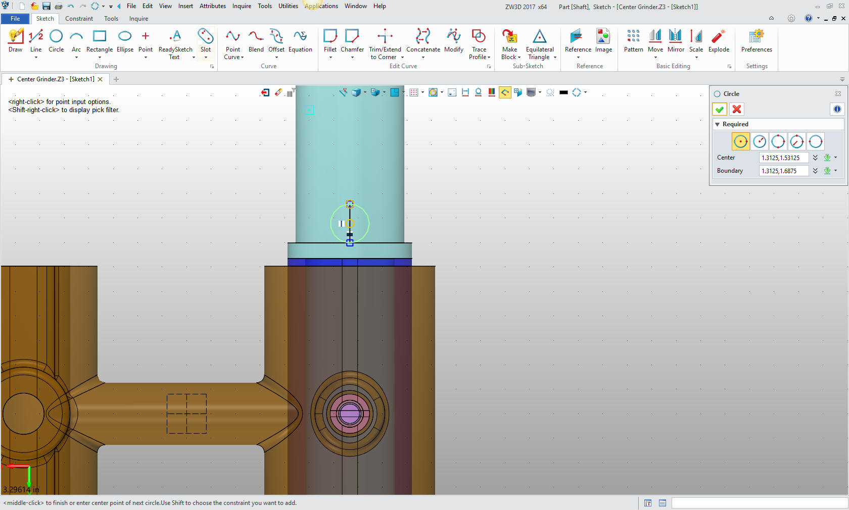
Now we
will add the circle in the sketch. I create a vertical line 5/16
long from the center of the cylinder that represents the edge of the
hole. I then create a circle using the center and end of the line. I
will delete the vertical line and exit the sketch.
I will
then extrude the hole. I have to set the view to wireframe to access
the sketch. We select the circle and set the size.
Now
for the last hole. We again go to the primitive cylinder, locate and
size. You are probably bored with this by now. But realize the time
is saves from having to create a sketch and then extrude.
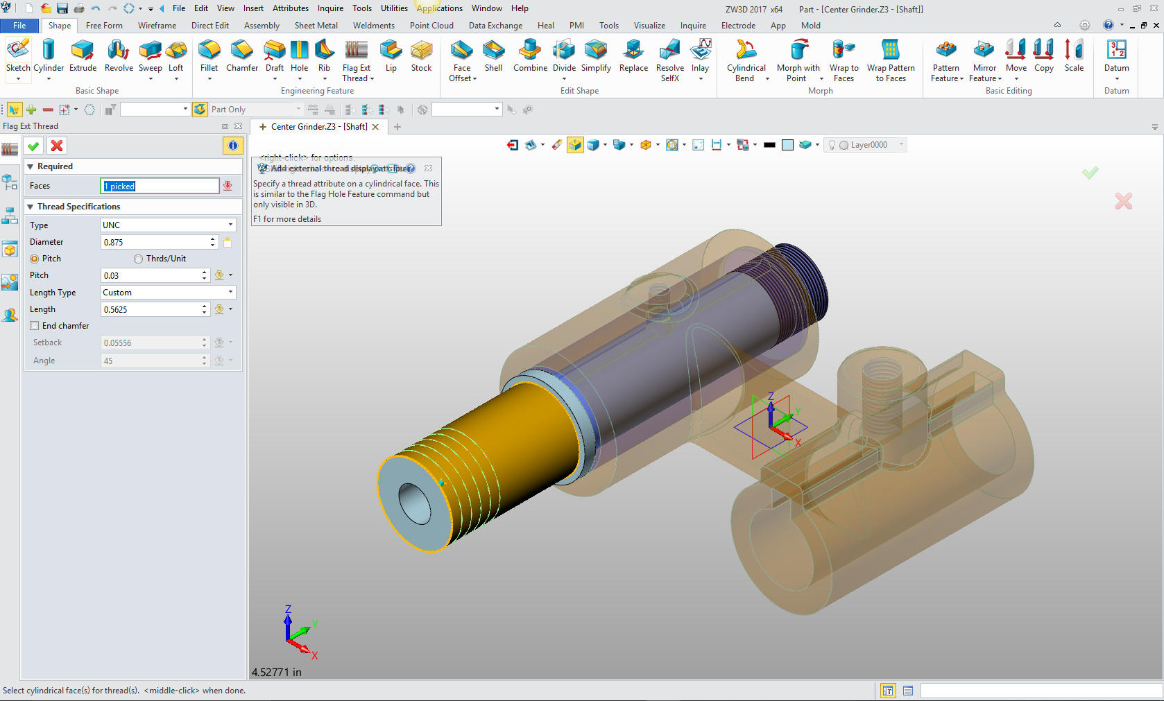
We now
need to add the cosmetic threads.
We are
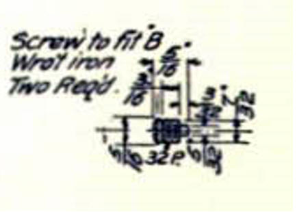
done with the Sleeve. I will change the color and move to the screw.
I have decided to alter the design a bit since the drawing is
not clear on the screw and how it sets in the Bearing. As we select
the Bearing to edit part, you can see the Bushing and Shaft are now
ghosted.
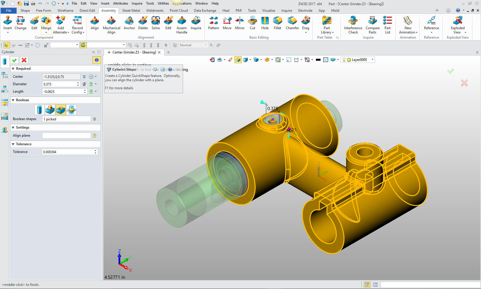
I will create a .375 X .063 deep counter bore in
the Bearing, again using the primitive cylinder. I want to do this
first so I can have the mating features to create the screw, saving
time from having to locate it.
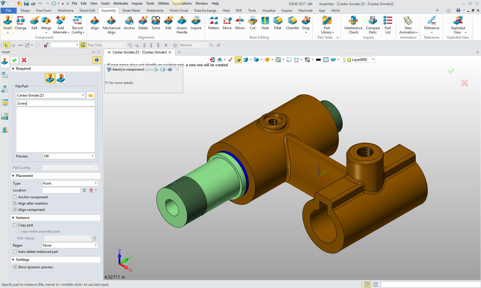
Now
for the screw. I have already modeled it in my IronCAD lesson, so I
will just recreate it here. I again insert a component "screw".
I could actually export it from my IronCAD part file. But this is a
modeling exercise. If you would like to see the two systems working
together go to his link. That would be a very informative productive
modeling techniques article.
3D CAD Systems Working Together
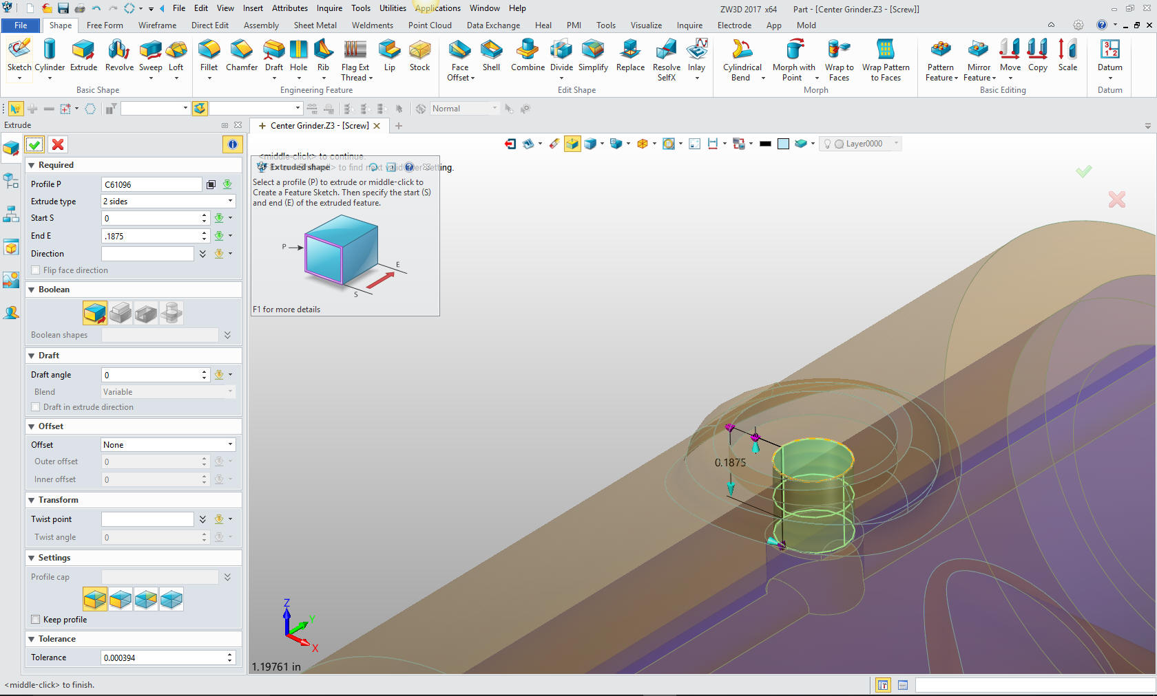
We
will again use the reference in the assembly menu to create the
screw body.
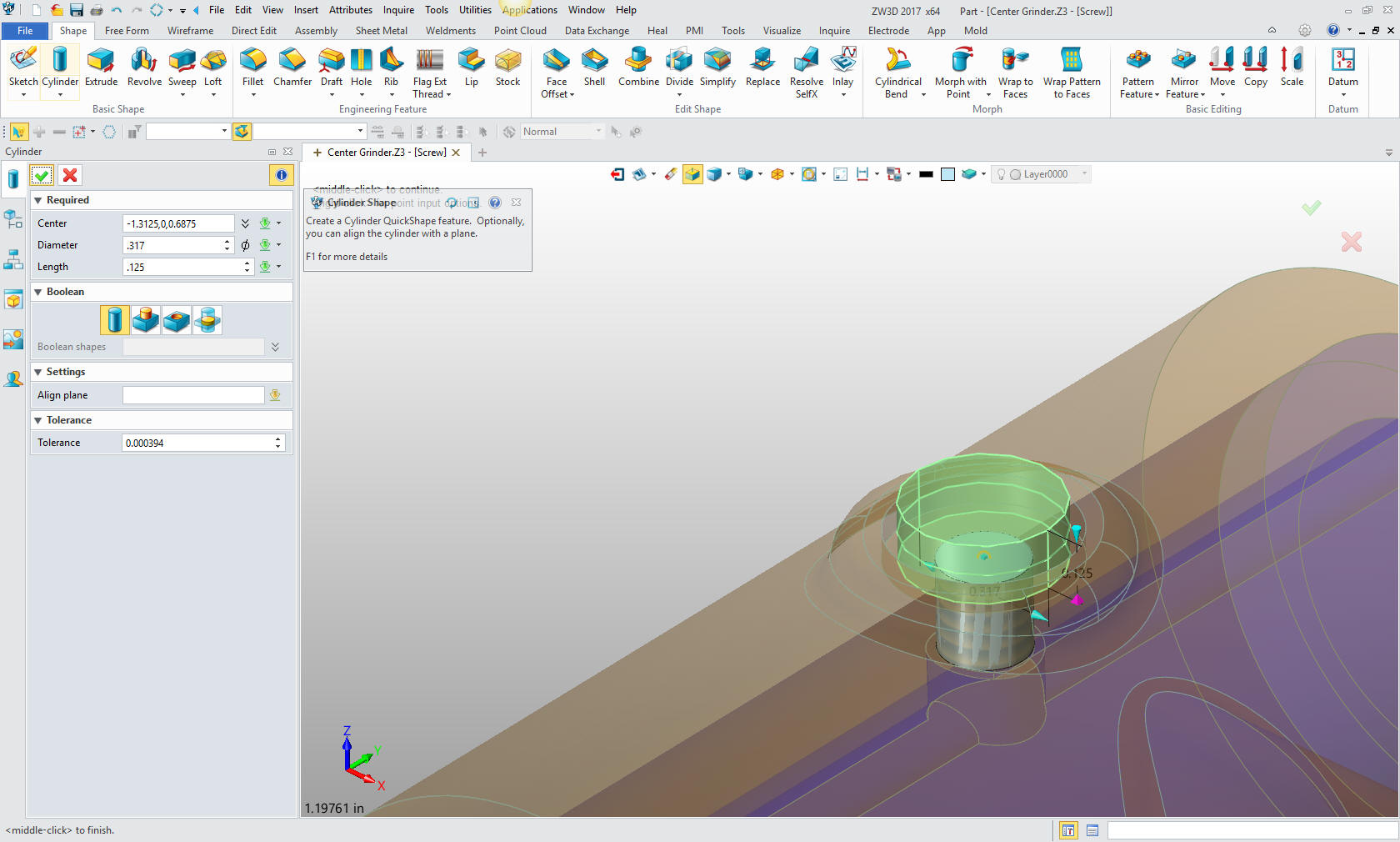
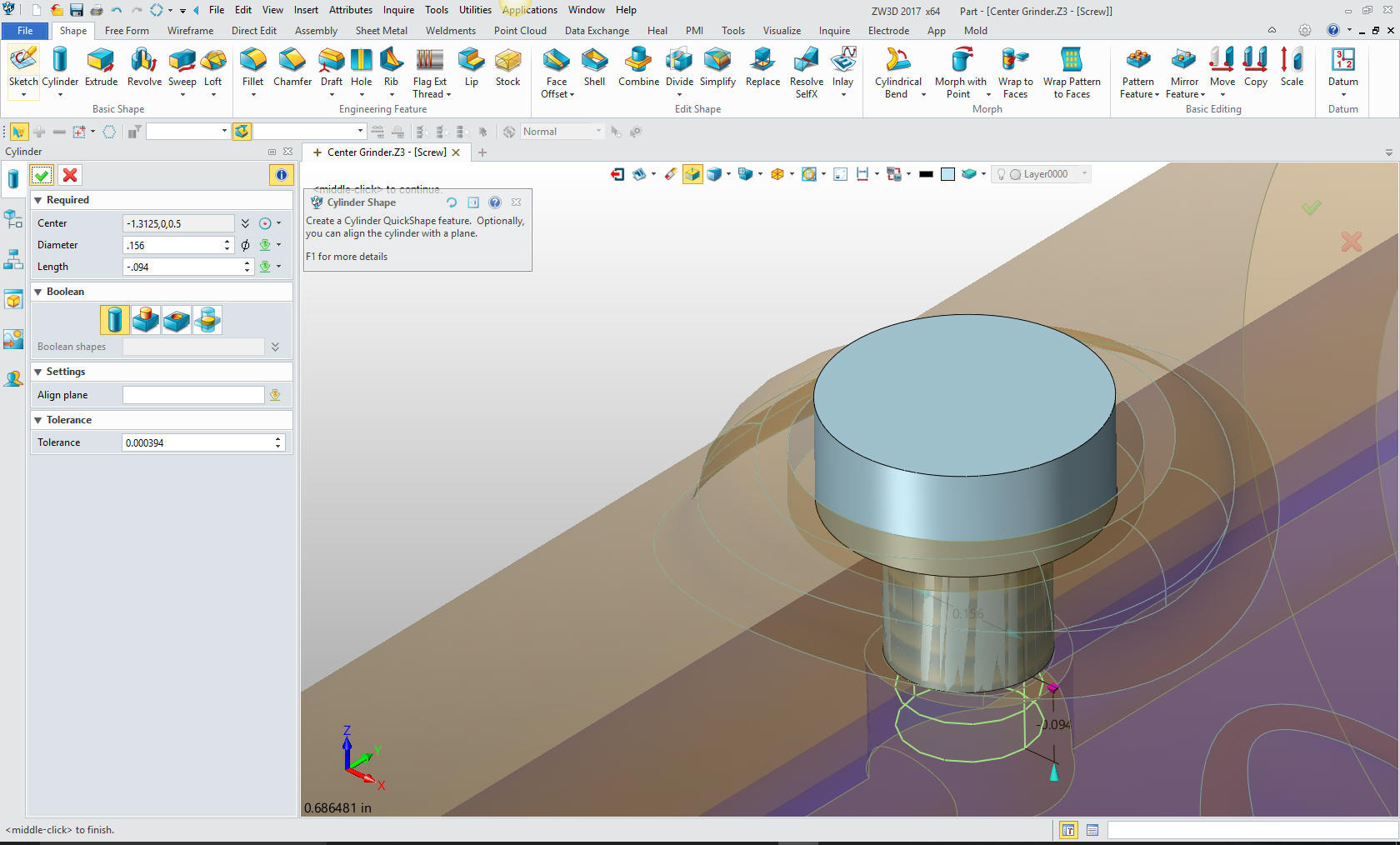
We
will now create the head of the screw, by creating a primitive
cylinder. locating and sizing. Have to admit I am getting good at
this and I am pleasantly surprised. I find ZW3D very, very easy to
use and highly productive.
Now
for the bottom boss. It is so cool that I can just select the edge
of the circle and define it to the center. Again i locate and size
the cylinder. I love this I didn't even have to manipulate the view.
This is huge!
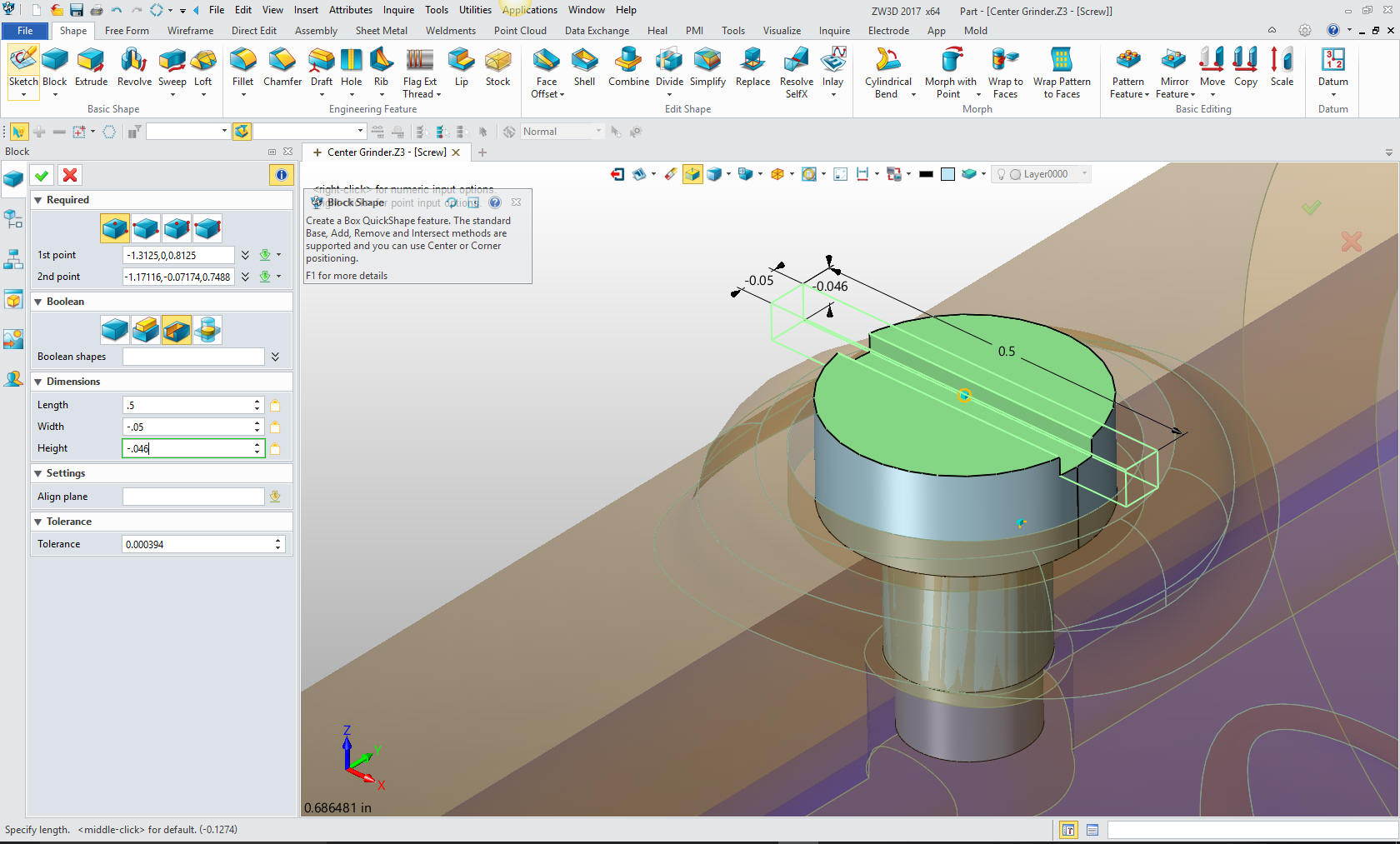
Now
for the slot on top. Yes, yes, yes, we insert a primitive block and
size it.
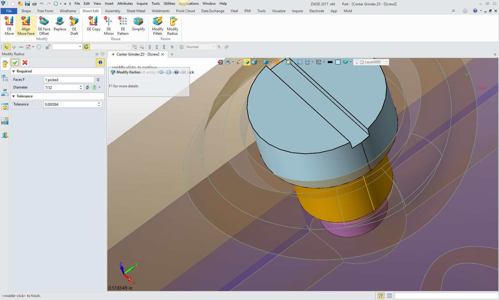
One
small step to add the screw thread cosmetic image. Hmm as I was
doing this I realized the screw body was the wrong size so I have to
go to the direct edit menu and set the body to 7/32 diameter. I like
have these mistakes show up, to show that we can edit the model in
any stage on the fly without having to edit a sketch.
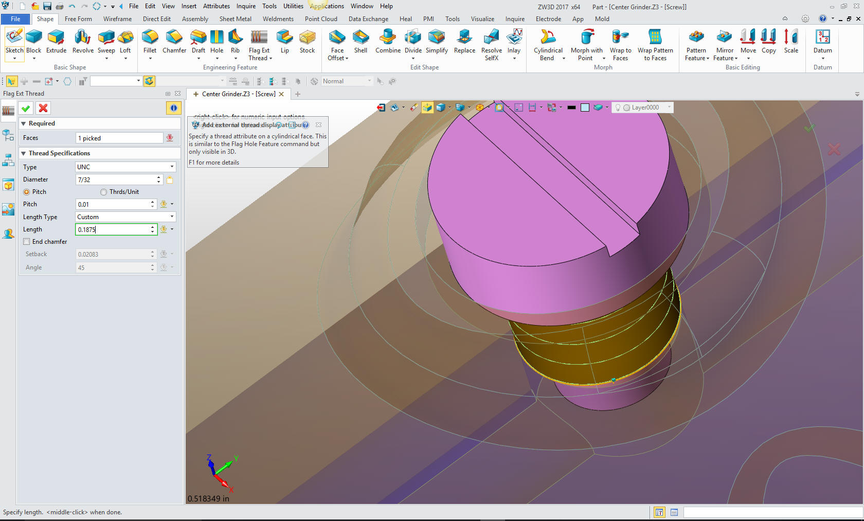
Now
for the cosmetic thread. This feature shows the the thread as a
feature in the drawing.
We are
done with the parts we are doing today.
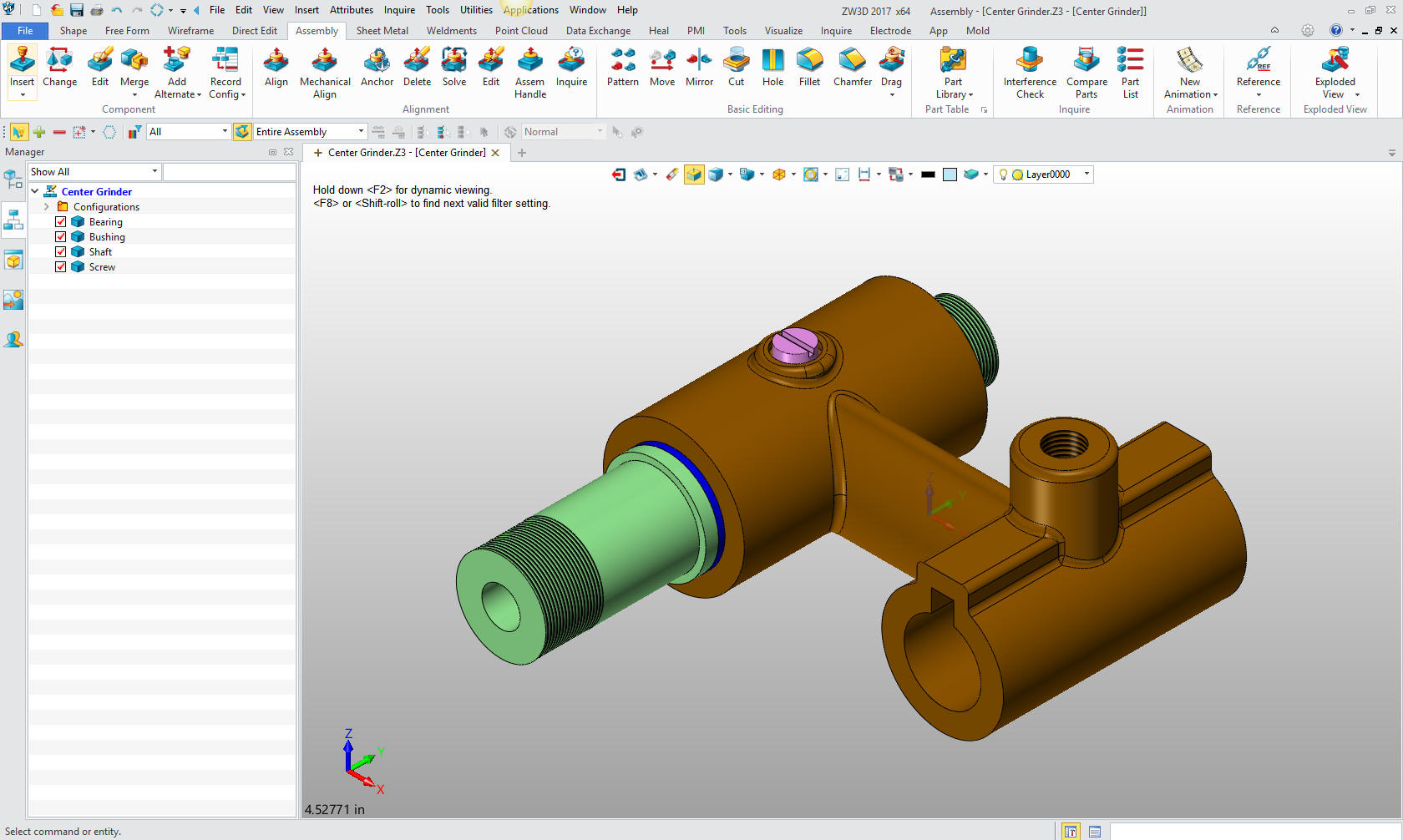
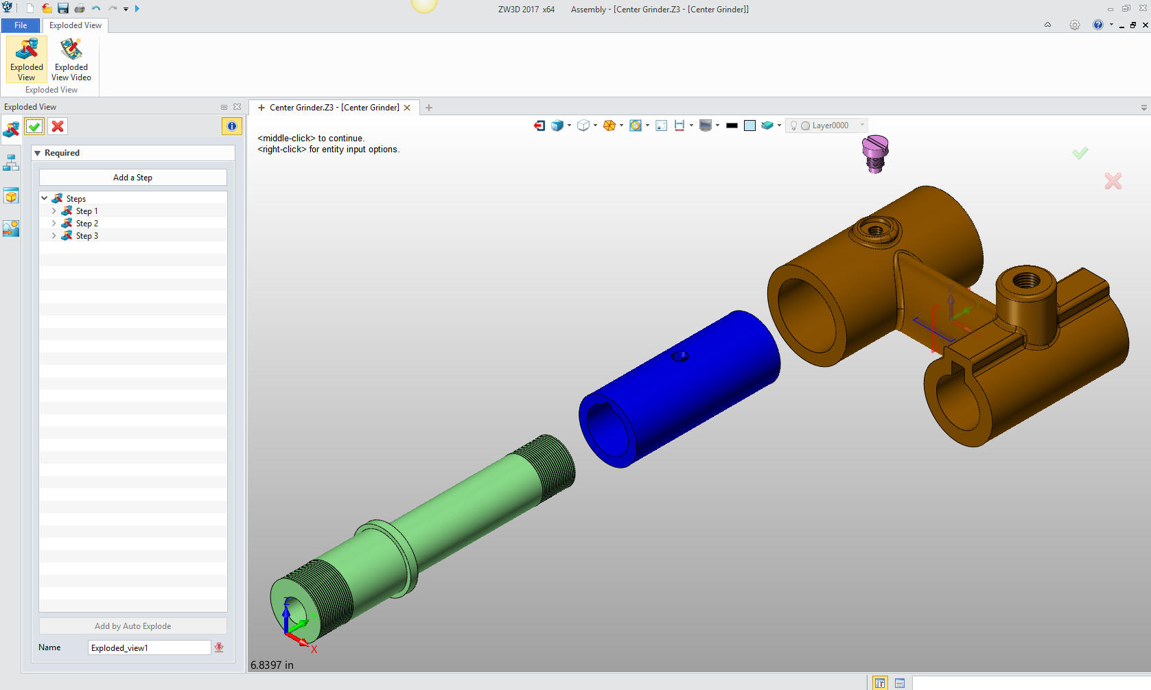
Here
is an exploded view.
Here
are the views defined in the 2D sheet generated from the Center
Grinder assembly. We add the dimensions and we
are completely done with the part. Please remember, we have done
this all in one file. Think it through!
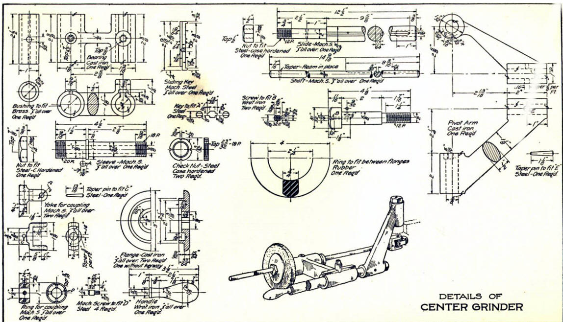
Here
is the original. I did add some dims that were not defined.
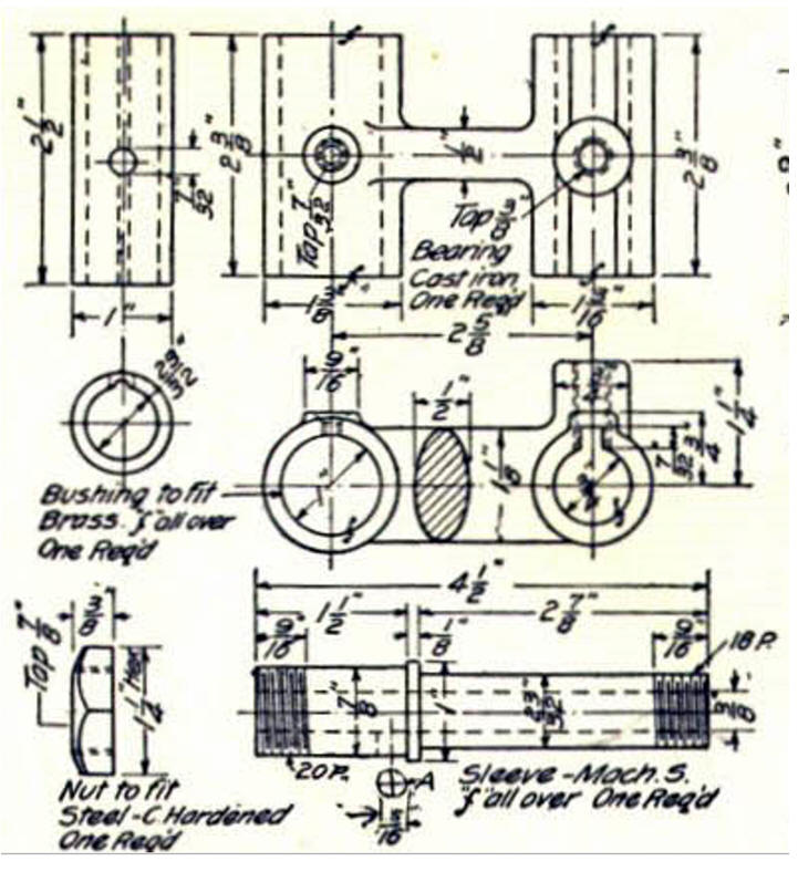
I did modify the screw. You can imagine
that this designer was avalable to manufacturing to answer any
questions.
Now for lesson
three:
3D Modeling Techniques IronCAD Lesson Three
If you would like
to try ZW3D, please download for a 30 day evaluation.
For more information or to download ZW3D
Give me a call if you have any
questions. I can set up a skype or go to meeting to show this part
or answer any of your questions on the operation of IronCAD. It
truly is the very best conceptual 3D CAD system.
TECH-NET Engineering Services!
We sell and
support IronCAD and ZW3D Products and
provide engineering
services throughout the USA and Canada!
Why TECH-NET Sells IronCAD and ZW3D
If you are interested in adding professional
hybrid modeling capabilities or looking for a new solution to
increase your productivity, take some time to download a fully
functional 30 day evaluation and play with these packages. Feel free
to give me a call if you have any questions or would like an on-line
presentation.
For more information or to download IronCAD or ZW3D
J oe Brouwer
206-842-0360
|
|