3D Modeling is the basis for our
engineering. That is the only place where productivity is paramount.
You can have all the PLM/MBE gurus debating data management, but it
does not add one smidgeon of productivity to the design process.
Top down or In-Context modeling is
the most productive feature of 3D CAD. Most systems tout this but
each part is still and external part. We are talking about a single
model of multi-object design environment. Both of the systems we
represent offer this as the "normal" design process. Thereby
increasing your productivity 20 to 30%.
In these exercises I not only focus on modeling techniques, but
also on much more productive systems to do our designs. I hope you
enjoy them and learn something. If you are in management, understand
that all 3D CAD systems are not the same. Cutting your engineering
costs is very simple. Even your legacy data is not a problem. Please
feel free to give me a call. There are millions of man hours wasted
every day with poor modeling techniques and ineffective 3D CAD
systems that cost a fortune. Productive 3D CAD systems do not have
to be expensive.
Joe Brouwer
206-842-0360
I am
doing the below assembly for an exercise showing my modeling
techniques and, of course, our superior 3D CAD
solutions.
3D CAD Modeling Techniques
I saw the following video challenges on linkedin and thought I would
give it a try on IronCAD. I got a great response and decided to do
it in ZW3D. I was very familiar with the parts and it was a bit
easier.
ZW3D vs Fusion 360
These exercises started out to show the benefits of
ZW3D over Fusion 360, but
quickly turned into a study of modeling techniques. Take a look at all of
them, they will open your eyes to a much different and more productive way of
modeling. It really has more to do with modeling technique than it has to do
with the 3D CAD systems. I have found that I do 3D modeling as compared to
the conventional 2D sketching. Of course, having a more productive 3D CAD
system doesn't hurt.
ZW3D is very similar to the Pro/e
clones with a few small differences. It is very easy for those users
to get up and running with ZW3D. It has a few operation that
are a bit more streamlined. The benefits over the other systems
are the multi-object environment (top down design) with the integrated drawing. You can
do parts, assemblies and drawings in one file.
These exercises were incredibly
popular and I thought I would follow up by showing more examples of
this 3D modeling technique.
We will be doing a
couple of parts each weekend in both IronCAD and ZW3D. I hope you
enjoy these exercises and hopefully they may lead to increasing your
productivity.
Please review lesson one:
3D Modeling Techniques ZW3D Lesson One
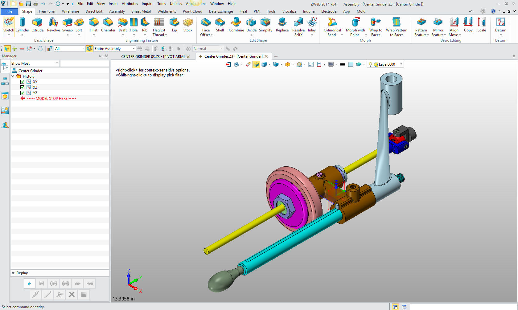
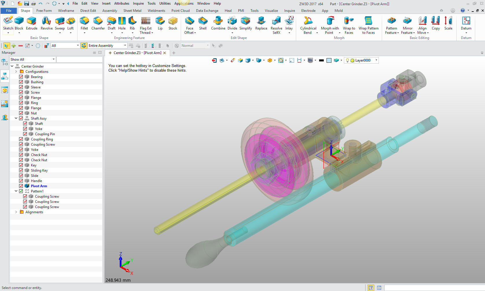
We will bring up the Center Grinder file:
Since we created this file as a multi-object the ZW3D Manager
automatically comes up. It shows the assembly and all the component
parts to this point.
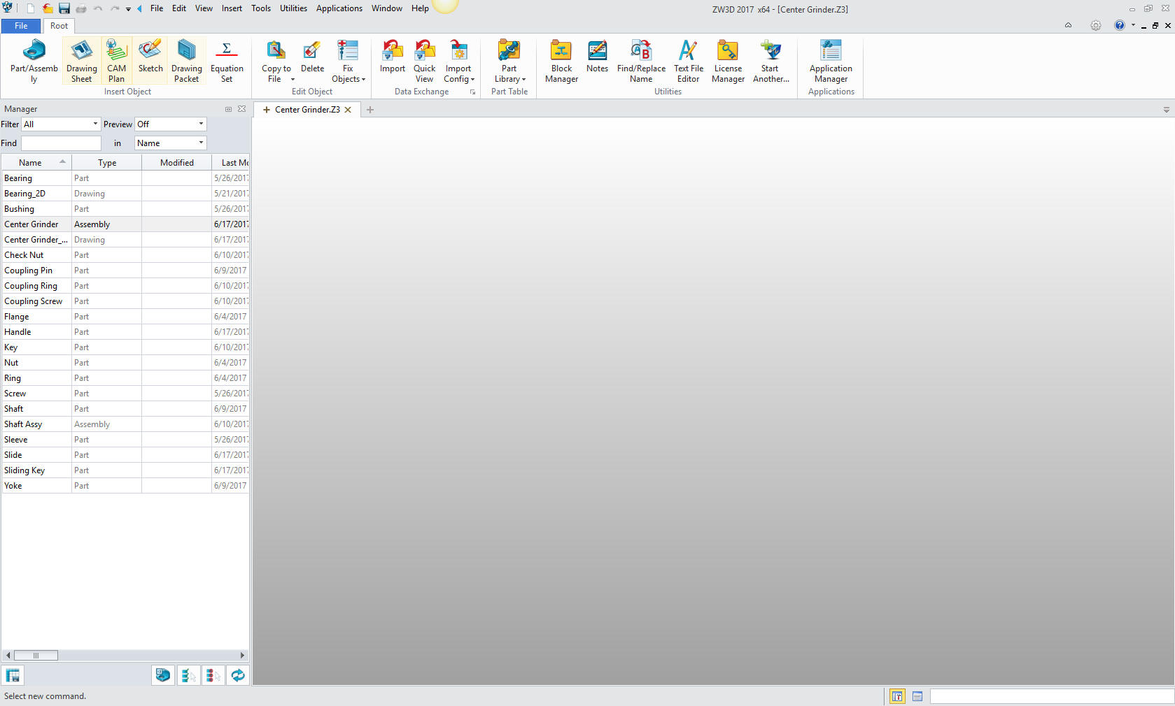
We will select the
center grinder assembly and we will see the existing parts. We will
right click on the Center Grinder assembly and select "insert
component". Again I want to reiterate this is not a true single
model environment. Each part is still like a external reference
except that it resides in the same file.
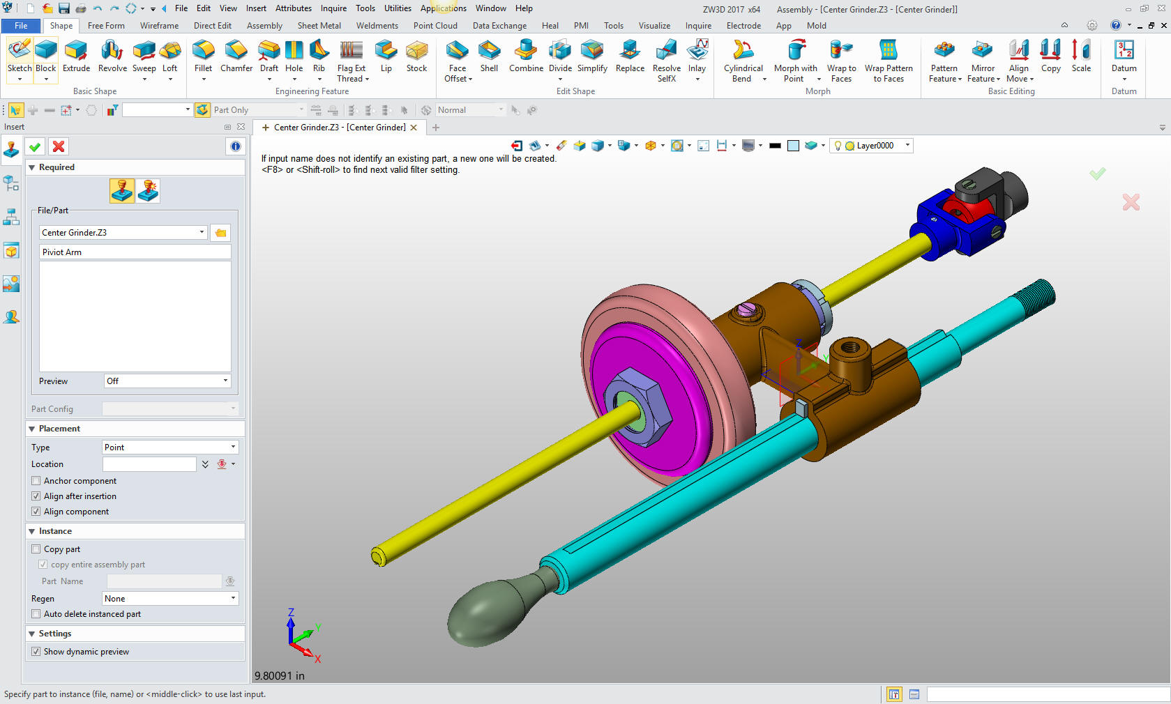
Now we
insert the Pivot Arm as a new part.
Note: ZW3D's Multi-Object
top down design is an incredible time saver. Especially for the
individual designer. Which is most of us. Even in large companies a
designer is given complete sub-assemblies to develop. The benefit
of designing in top down and in a single model or Multi-object
environment is that we design in aircraft position, I have been
informed that automotive has car position. This how I have designed
since 1986 while at Boeing with CADKEY. Top down design in the
single model environment was the one reason I could not move to the
Solidworks clones.

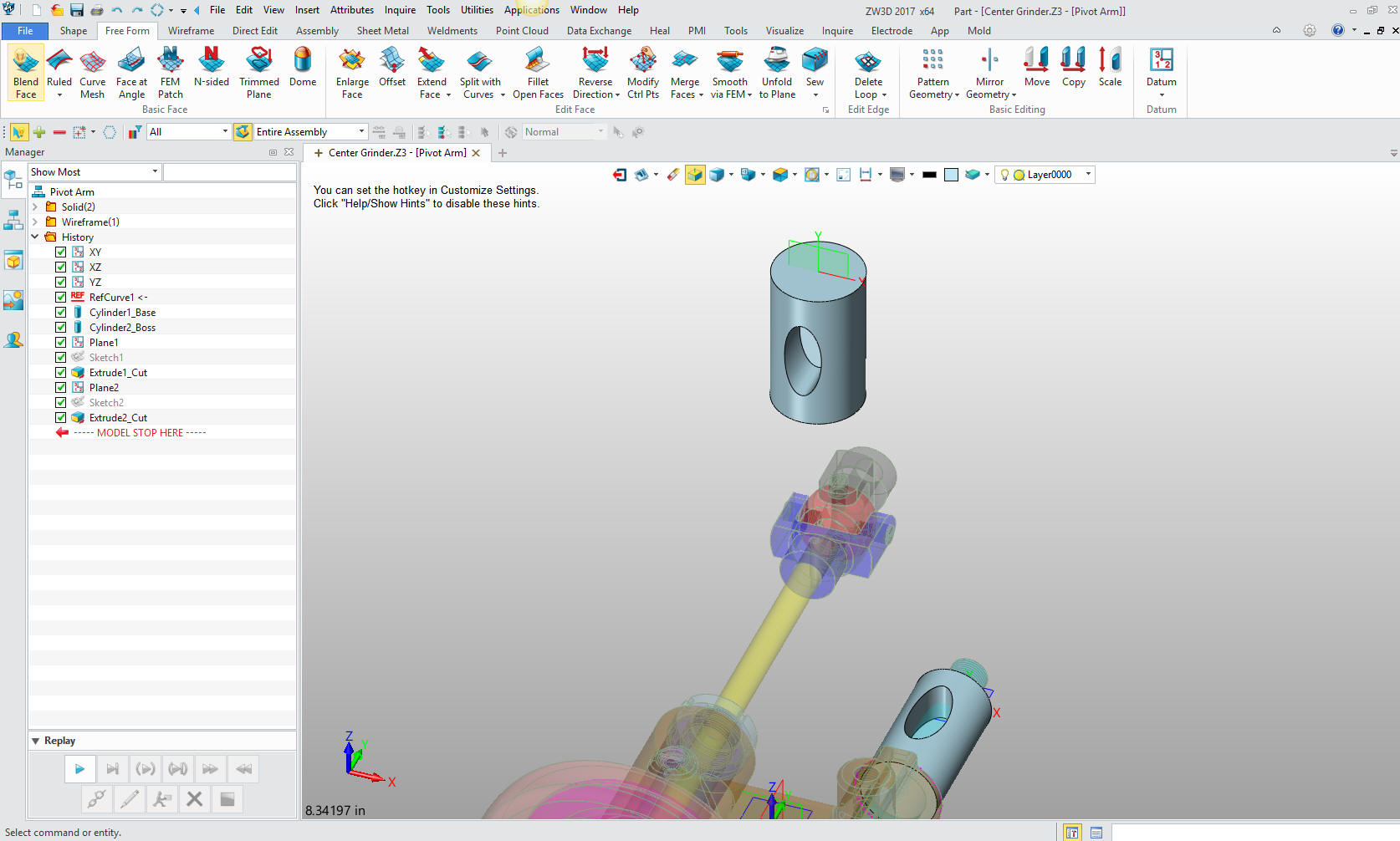
This
step automatically puts us in the "edit part" mode that shows the
other parts as ghosted. They are available for reference as you
will see. We also have the "open part" mode which has only the
single part available. You can make these external individual parts
as required.
Note: I have surprisingly found that ZW3D is a
superior top down design program. I have worked with many top down
design packages (There are only 4 that I know of) and ZW3D is
incredibly productive.
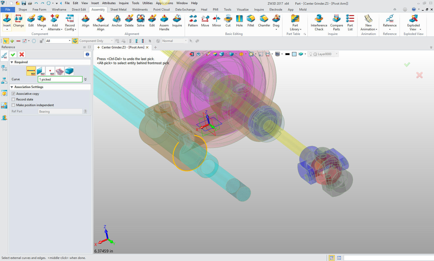
Now
will will begin on modeling the Pivot Arm. We are going to design in
top down or in context design. We go to the assembly menu and select
Reference and select the edge of the mating part.
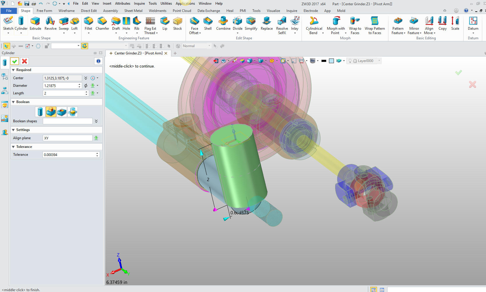
We
insert a primitive cylinder centered on the curve and aligned to the
correct plane. We size the cylinder.
Note: working with primitive is incredibly productive, i would
say it increases productivity 30% and simplifies your modeling
process.

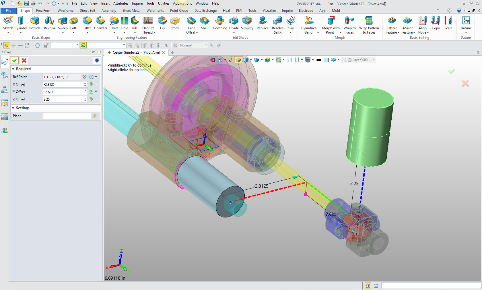
We
insert the next primitive cylinder on the center of the end of the
existing cylinder and create it vertical. We size the cylinder.
From
the center of the cylinder we will move the cylinder to the correct
location. We will not select the move command we will just edit the
cylinder which includes location.
We now
create the plane for creating the ellipses.
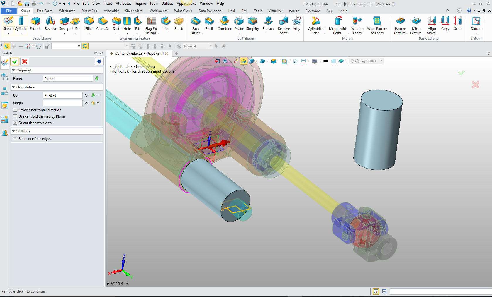
We
create a ellipse in the center of the cylinder. I create a line in
the center of the cylinder then create the ellipse at the mid-point.
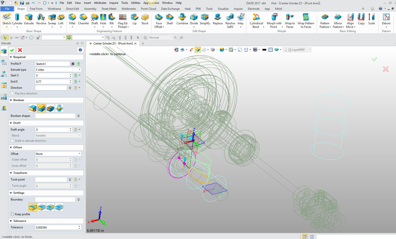
I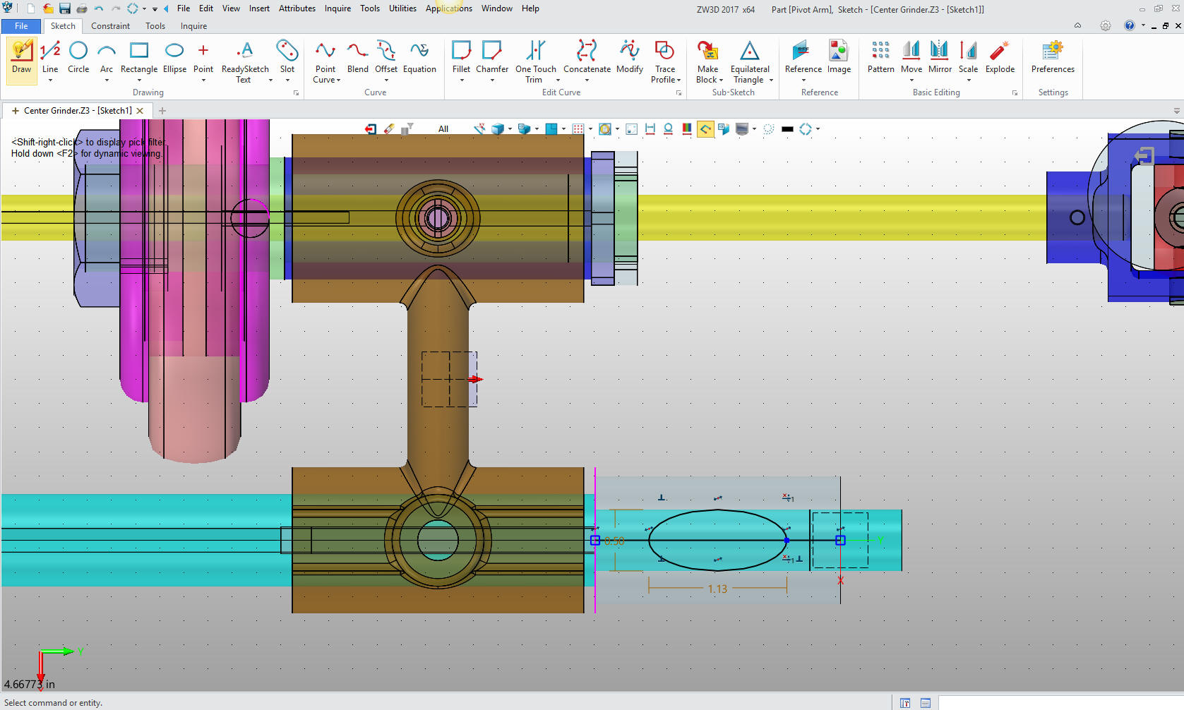
I will delete the construction line and exit the sketch. We now
extrude the profile to the correct length. I have to turn it to wire
frame to select the profile.
Now we
create the other plane on the vertical cylinder and we have both
ellipses for reference to create the arm
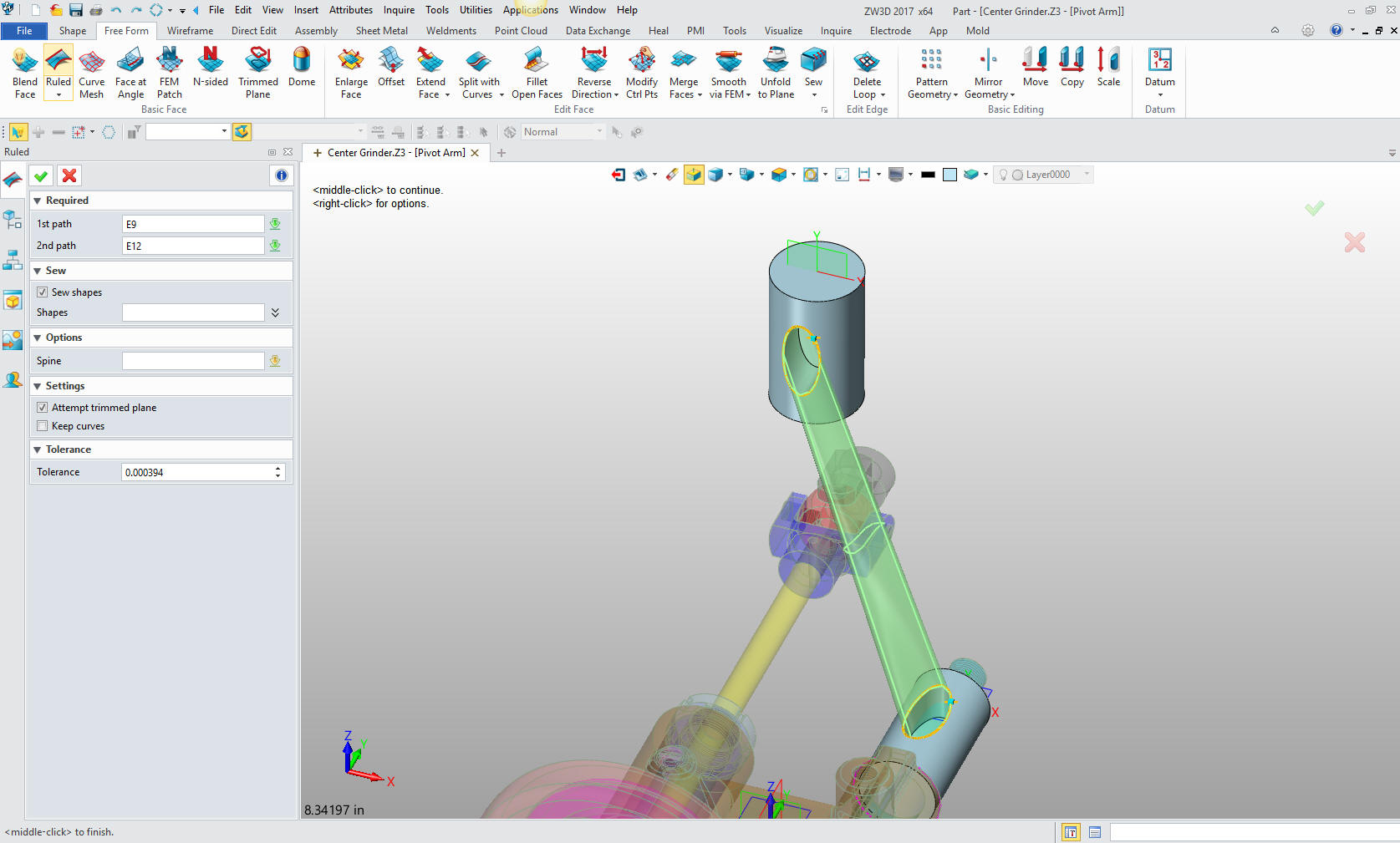
We
used ruled surface to create the arm.
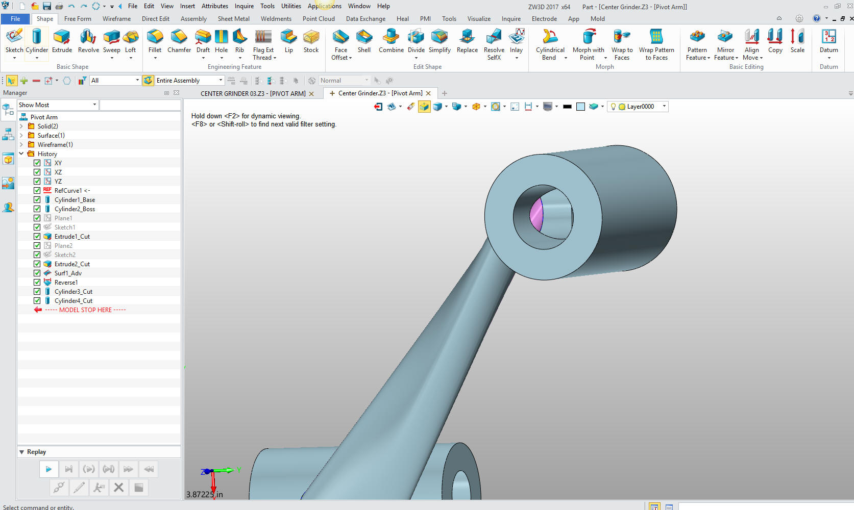
We now
add the holes
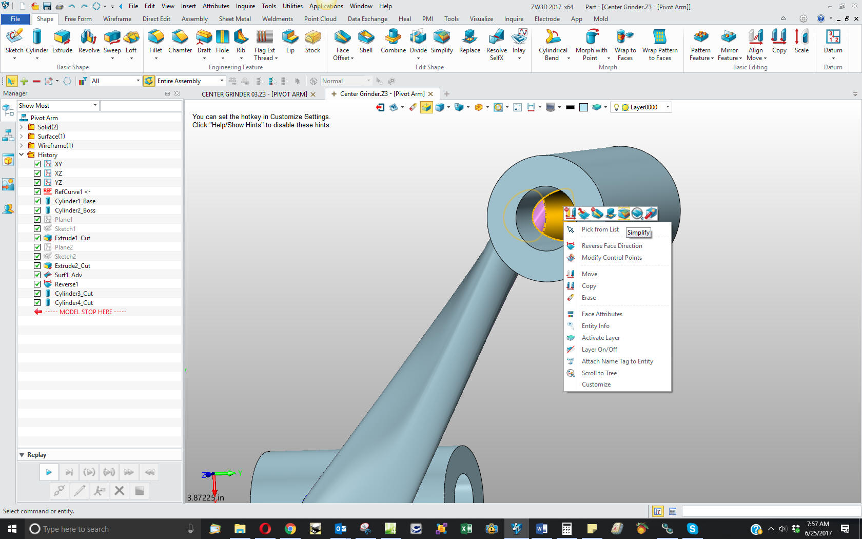
We
eliminate the reference elliptical holes with simplify from direct
edit. Now there maybe a better way of doing this, but it does show
the use of direct edit in your design process. We are actually doing
hybrid modeling with this part.
I
eliminate both holes with the direct edit simplefy command.
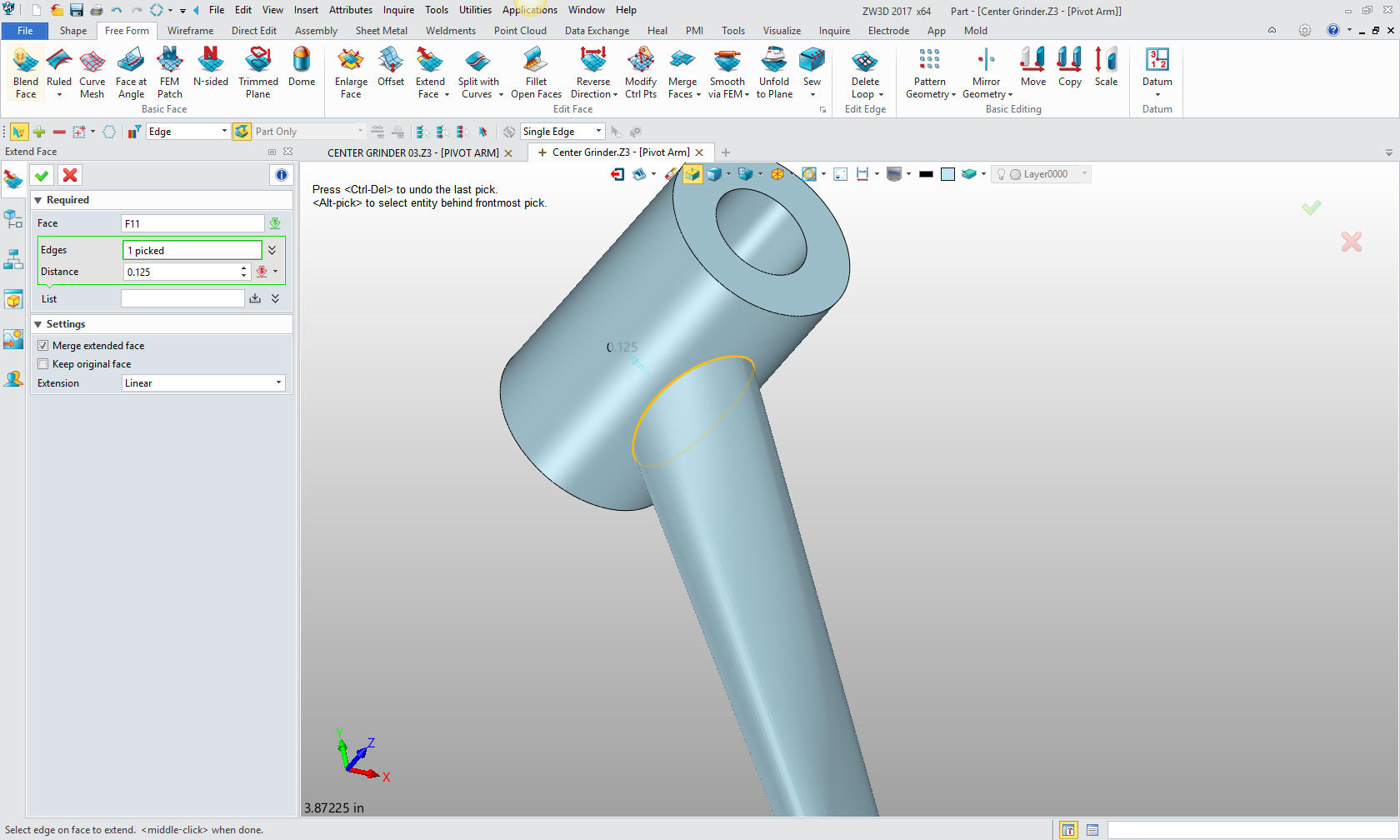
We
now extend the surfaces into the cylinders .125.
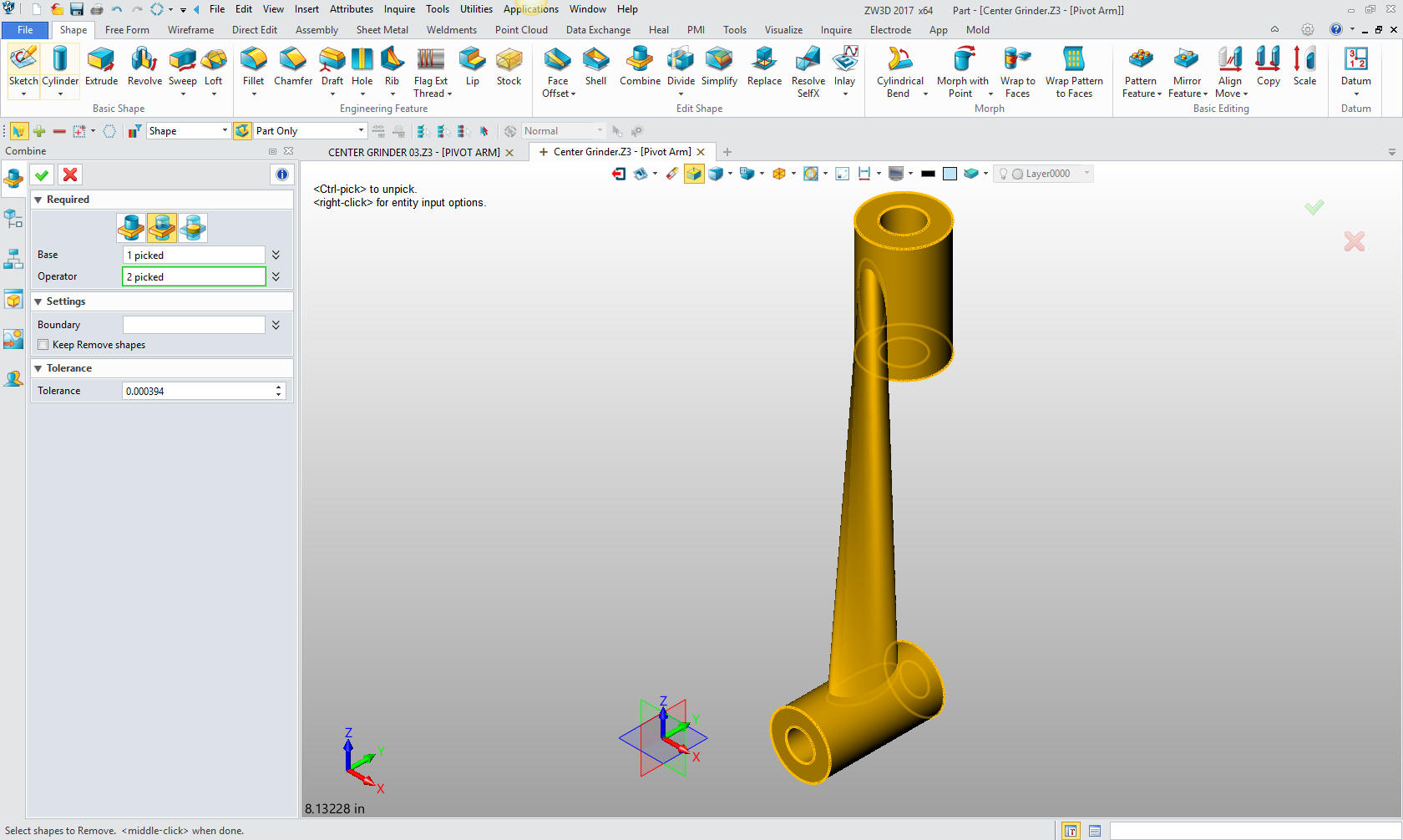
Now we combine the parts using the arm as the base and the
cylinder as the operators.
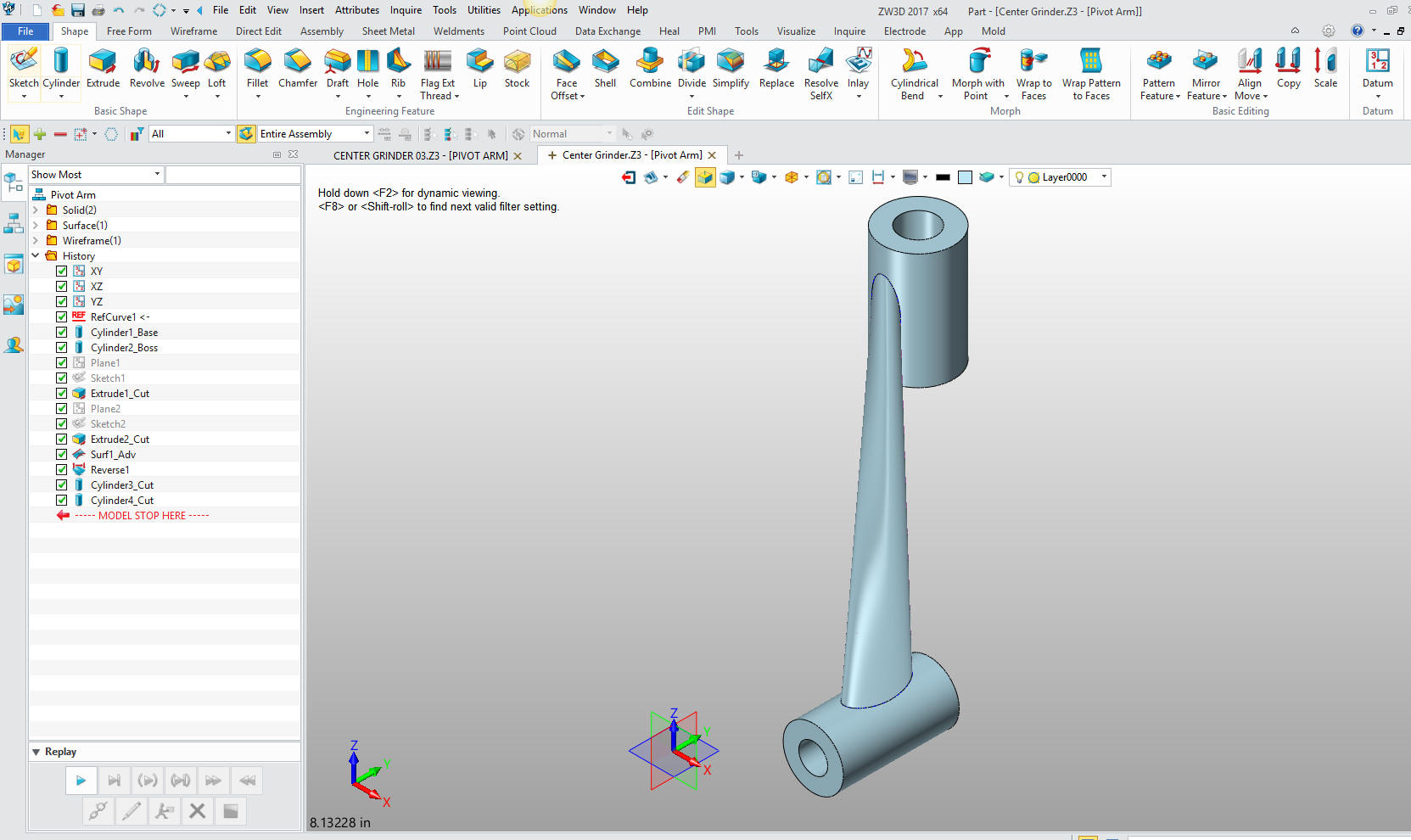
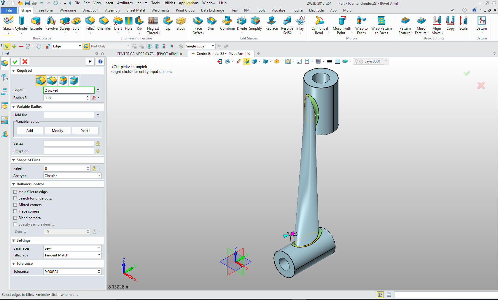
Now
to put in the fillets.
One
more little cut and we are done.
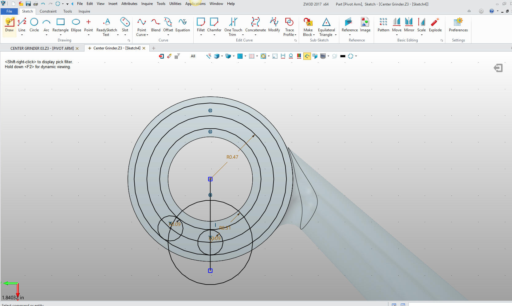
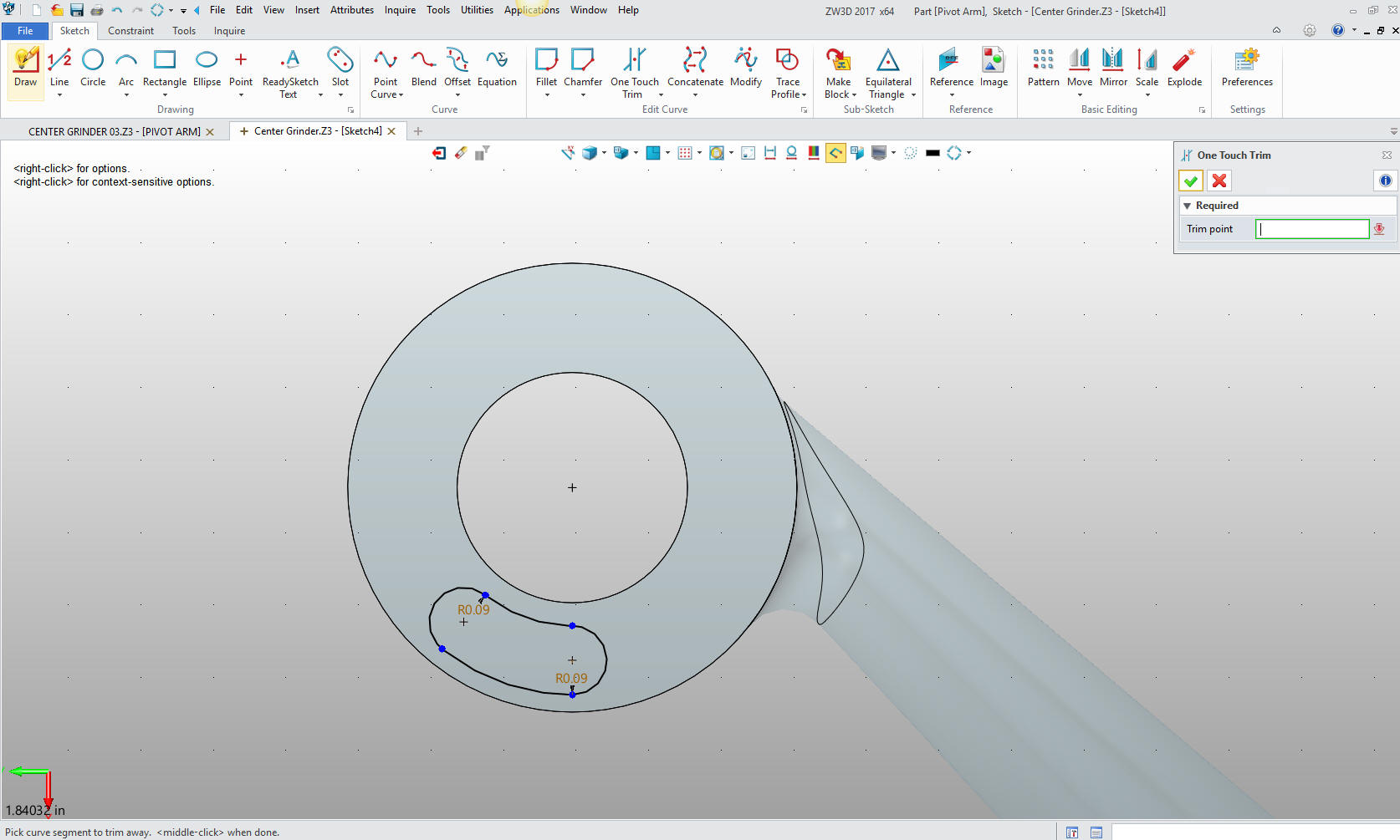
We model the small slot in the bottom of one of the cylinders and we
are done with this part. We will do this using the extrude wizard. I
will show you my sketching technique. I projected the center circle
and edited the size to 15/32, then offset that line by 3/32 both
sides. I then created the circle to locate the center of the 3/32
radius then create the two 3/32 radii.
I will just trim and delete the construction geometry. I know many
of you would probably do this much different.
We
exit the sketch and we extrude to the correct depth and we are done
with the part.
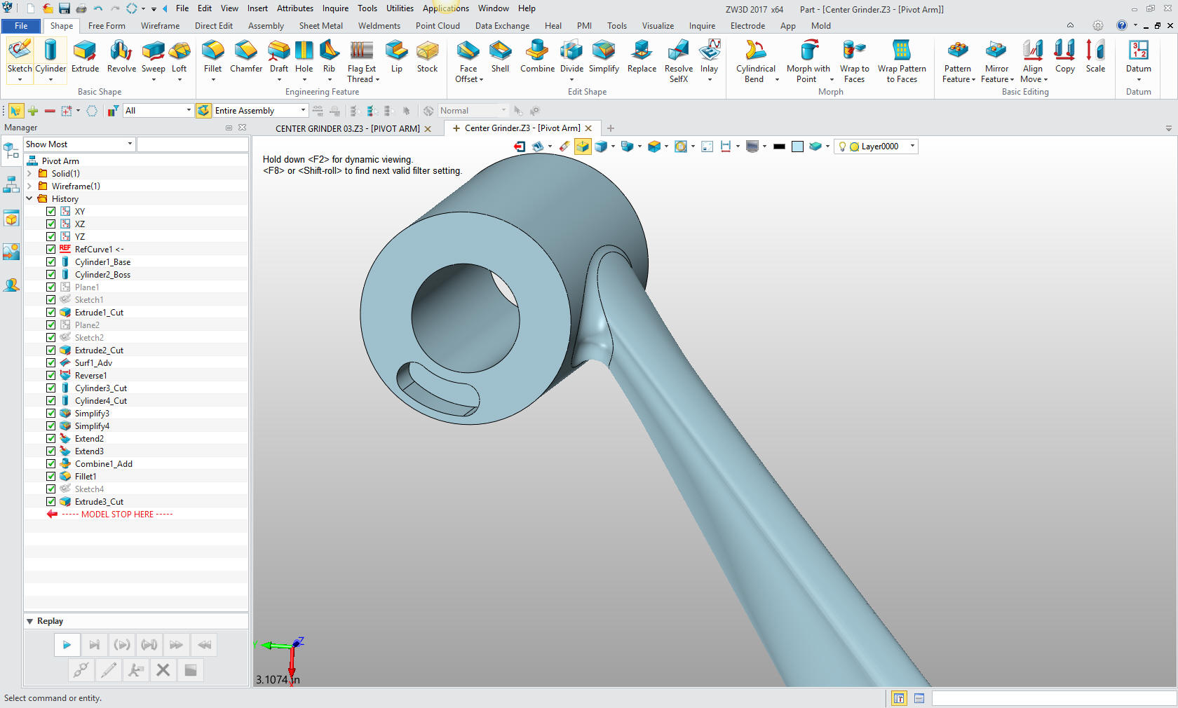
Here
is the assembly to date.
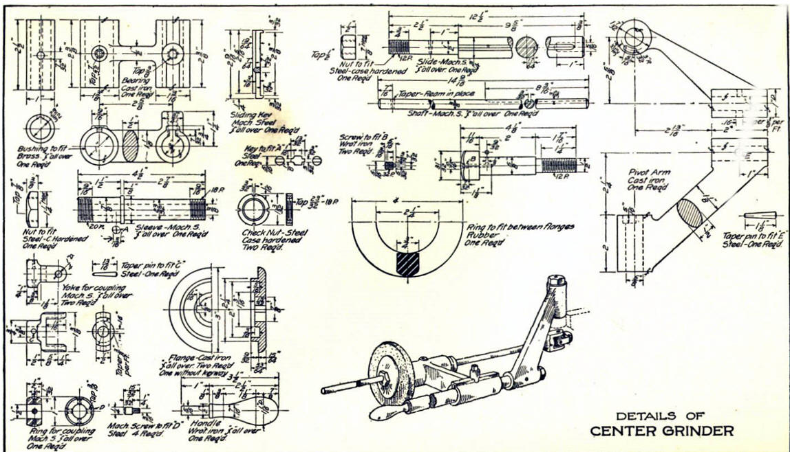
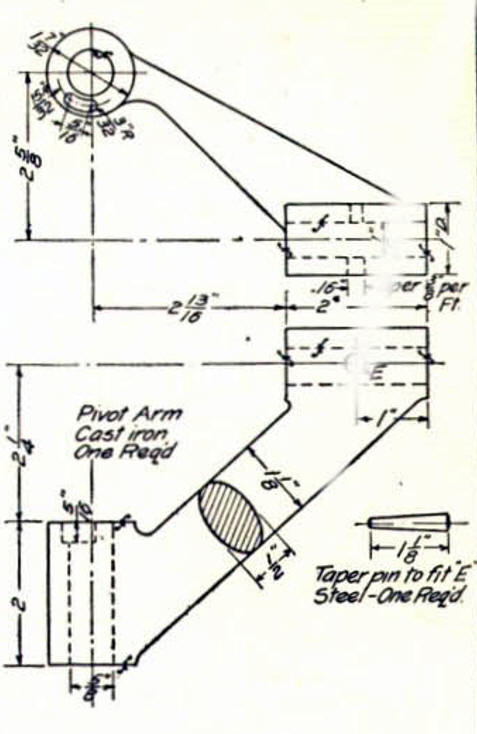
Here
is the original. I did add some dims that were not defined.
If you would like
to try ZW3D, please download for a 30 day evaluation.
For more information or to download ZW3D
Give me a call if you have any
questions. I can set up a skype or go to meeting to show this part
or answer any of your questions on the operation of IronCAD. It
truly is the very best conceptual 3D CAD system.
TECH-NET Engineering Services!
We sell and
support IronCAD and ZW3D Products and
provide engineering
services throughout the USA and Canada!
Why TECH-NET Sells IronCAD and ZW3D
If you are interested in adding professional
hybrid modeling capabilities or looking for a new solution to
increase your productivity, take some time to download a fully
functional 30 day evaluation and play with these packages. Feel free
to give me a call if you have any questions or would like an on-line
presentation.
| |