IronCAD vs Fusion 360 Lesson 15 3D Modeling Techniques Defined Streamlined
Sketching/Feature Based Modeling
This part that is so simple it
strains credulity to watch this fellow struggle with it. He takes
the drawing and starts creating features that just don't make sense.
He doesn't evaluate the features that make up the part. I can tell
you being in a "Constrain Sketching Only" box is an incredibly
limited and time
consuming process.
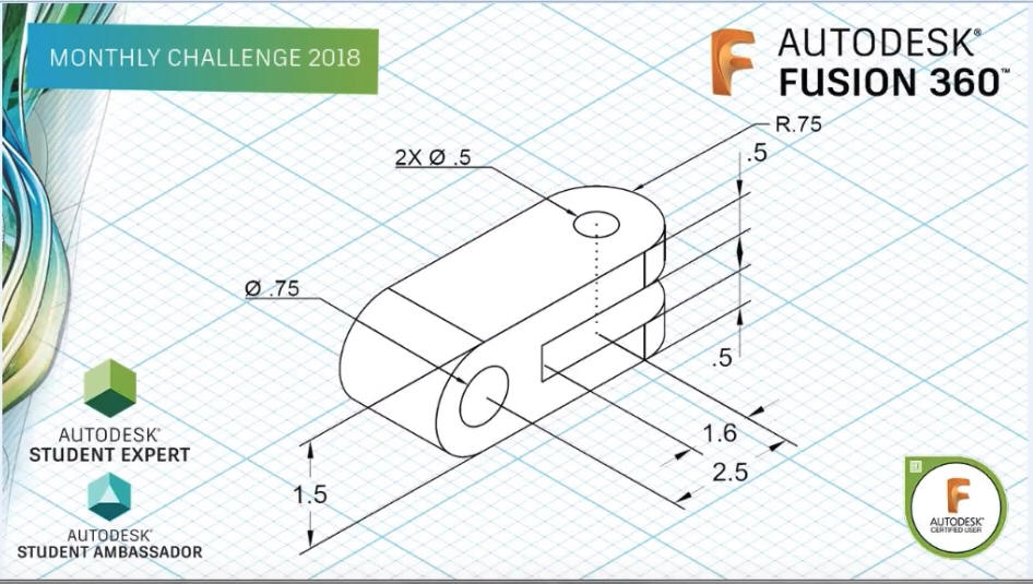
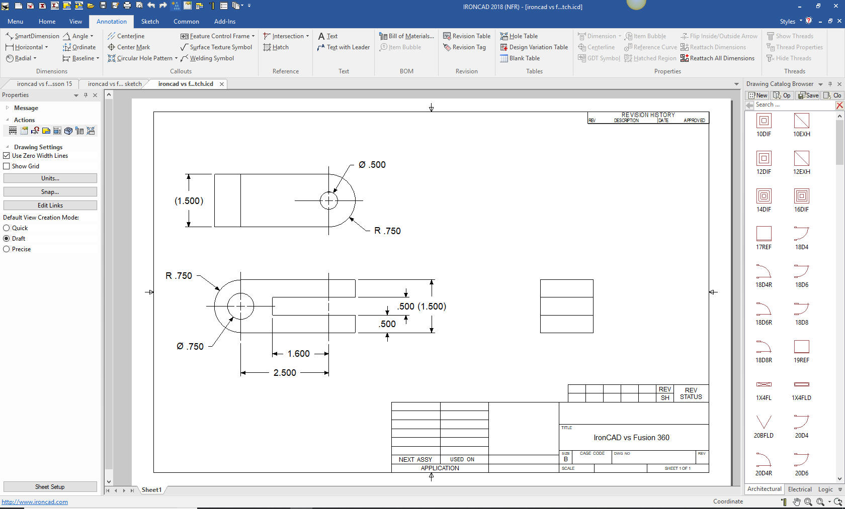
Lets take a look at this part. First we want to see the basic
feature. Not all parts are this simple. We can see a block. With a
little arithmetic we can see it is 4.00x1.50x1.50. That will be the
first feature we make and continue from there. We can see that the
cutout is 2.35x.50. Those are the only created features the others
are four .75 blends and two holes.
I have debated with a few
about constrained sketching and when the part goes to CNC it is a
dumb part. The only way you define relationships is detailing the
part in the AID (Associated Information Document).
We are
already in inches so let get started.
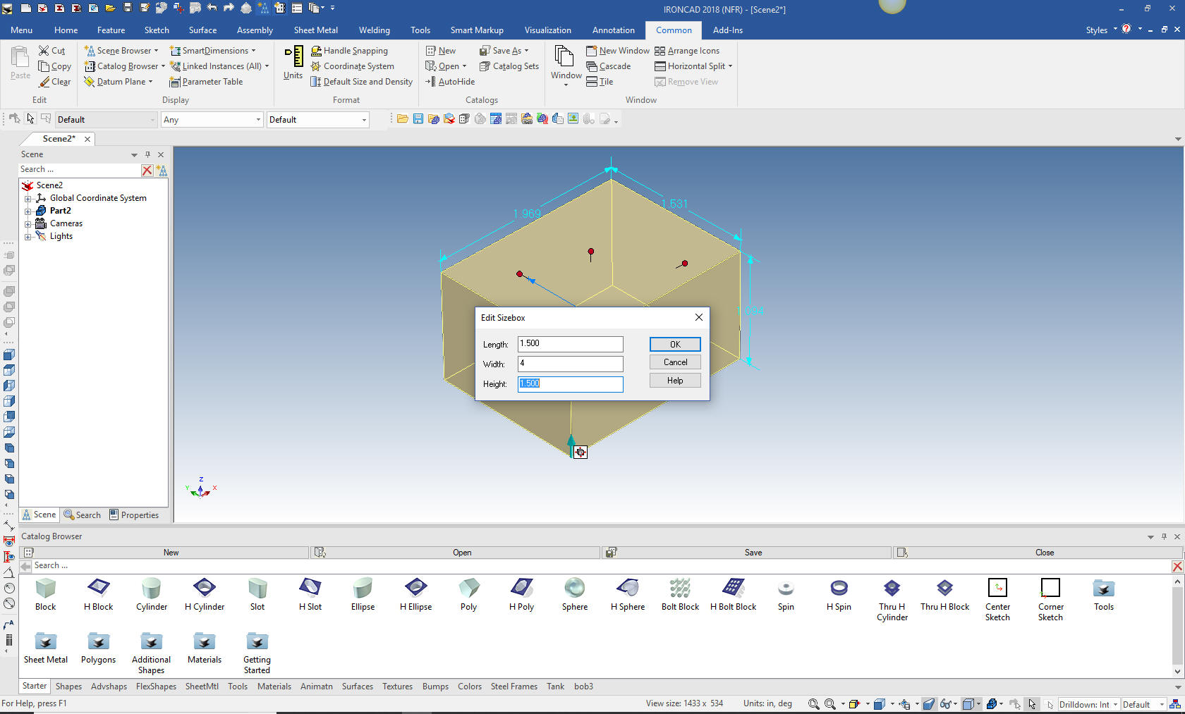
We drag and drop a
block from the standard catalog and size it.
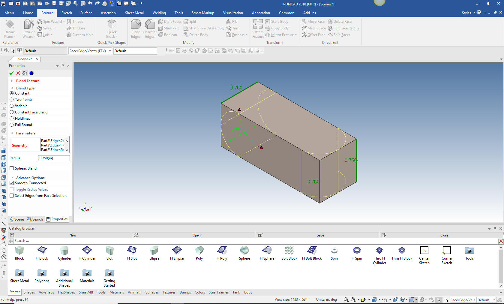
Now we add the blends since they are both the same we do them
all in one step. For the life of me I cannot understand why the
"constrain sketching only" crowd insists on sketching fillets.
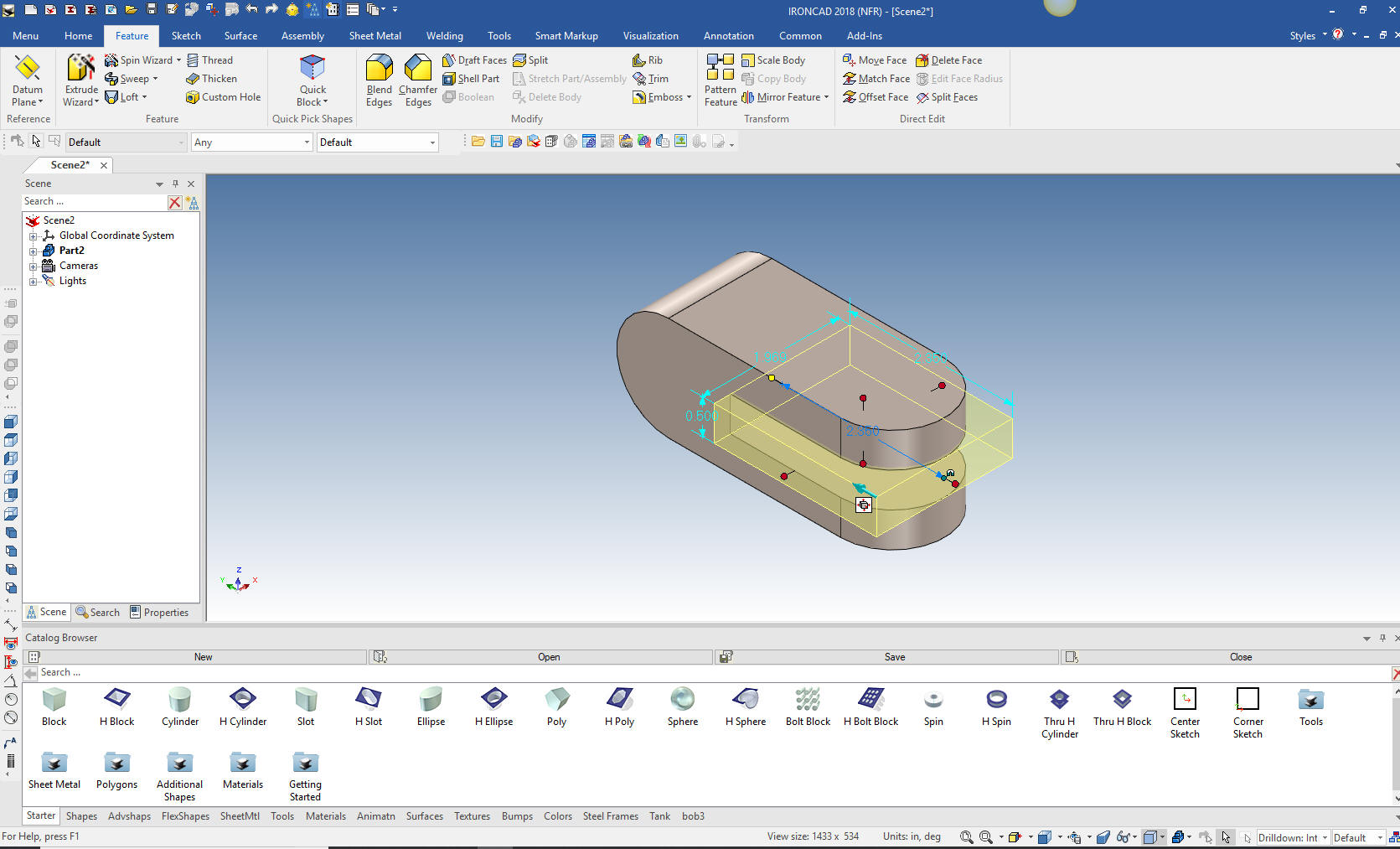
Now for the cut. I did the fillets before the cut do eliminate a
step. I drag and drop and hole block on the front face and size it.
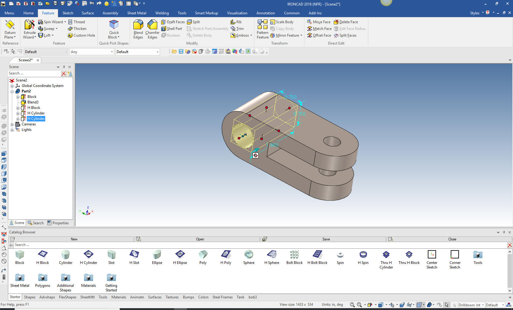
Now for the two holes. We drag and drop two hole cylinders on to
the relevant faces and size them. IronCAD automatically recognizes
center, mid-points and corners.
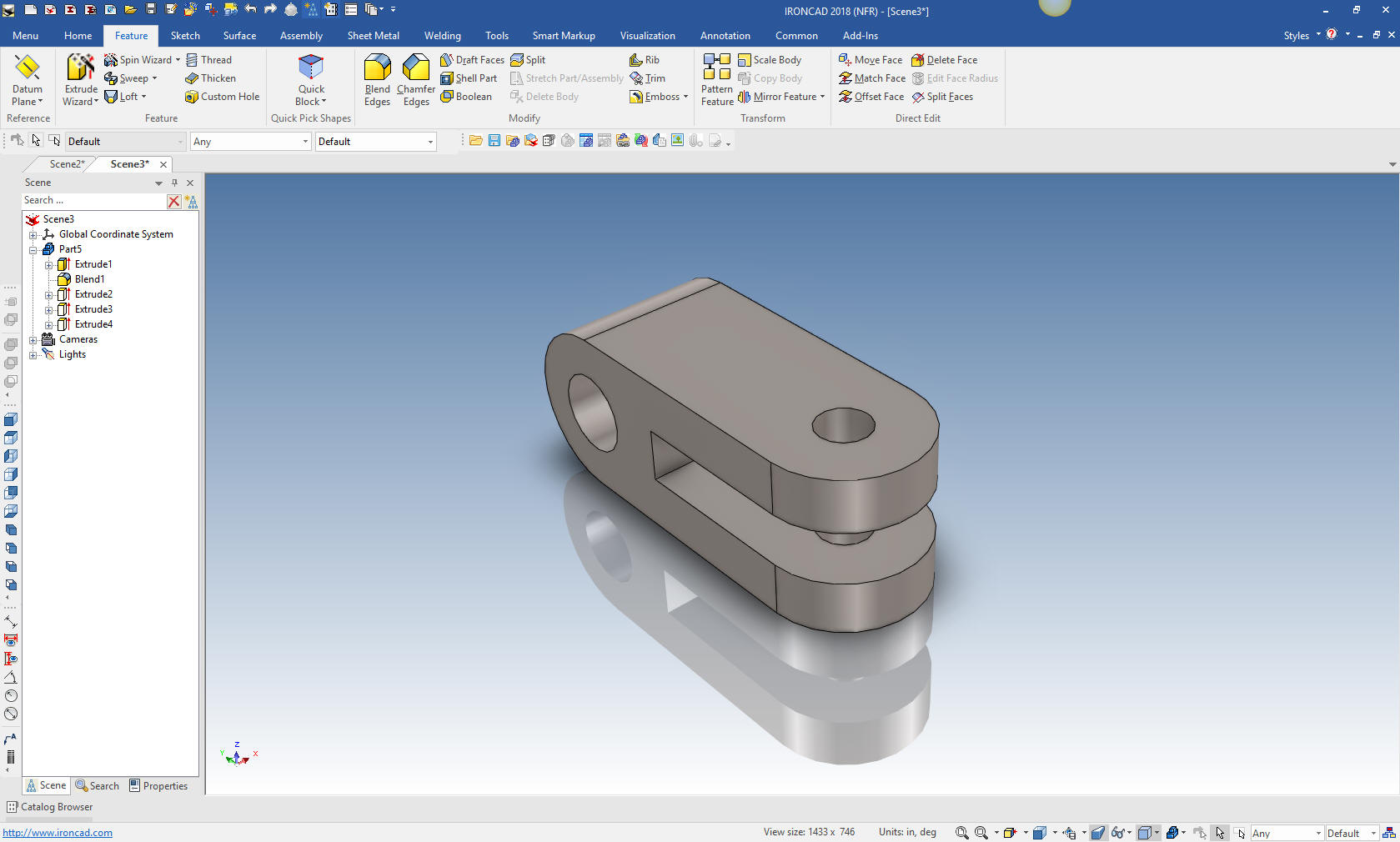
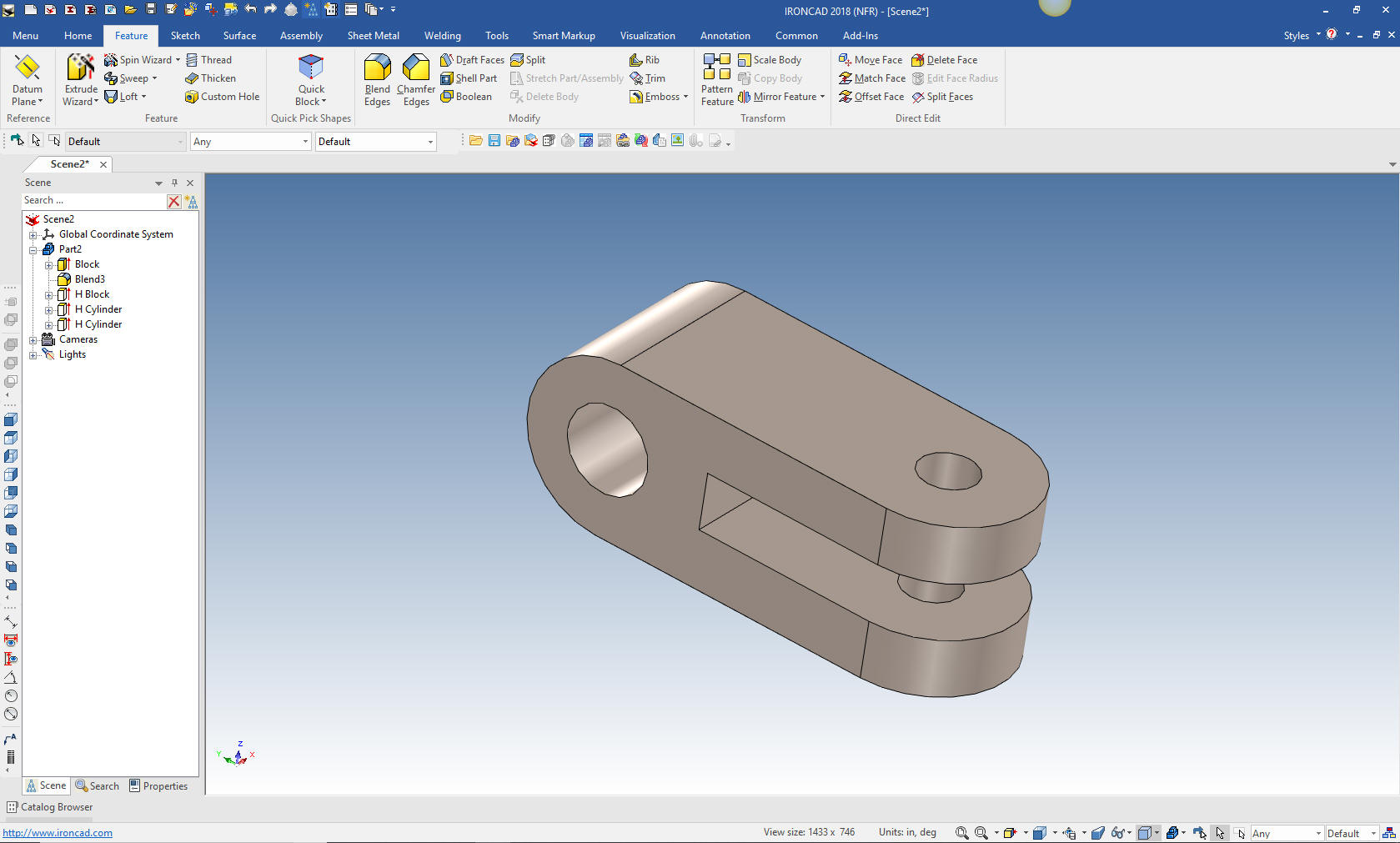
There you go. No sketching, just feature based modeling design
with shapes at its best. As you can see I have hidden the catalog.
You usually operate it in an autohide mode to give you more design
real estate.
I know, I know, not all of you have intellishapes to design, in
fact probably none of you. So let's do it with sketches to show you
Streamlined Sketching using the same idea of looking at the part and
seeing the basic shapes.
When you design in IronCAD you
usually start by dragging and dropping Intellshapes from the
catalog, then you may use streamlined sketches or the integrated
direct editing. They are all available in your design process. Think
of the design flexibility this offers.
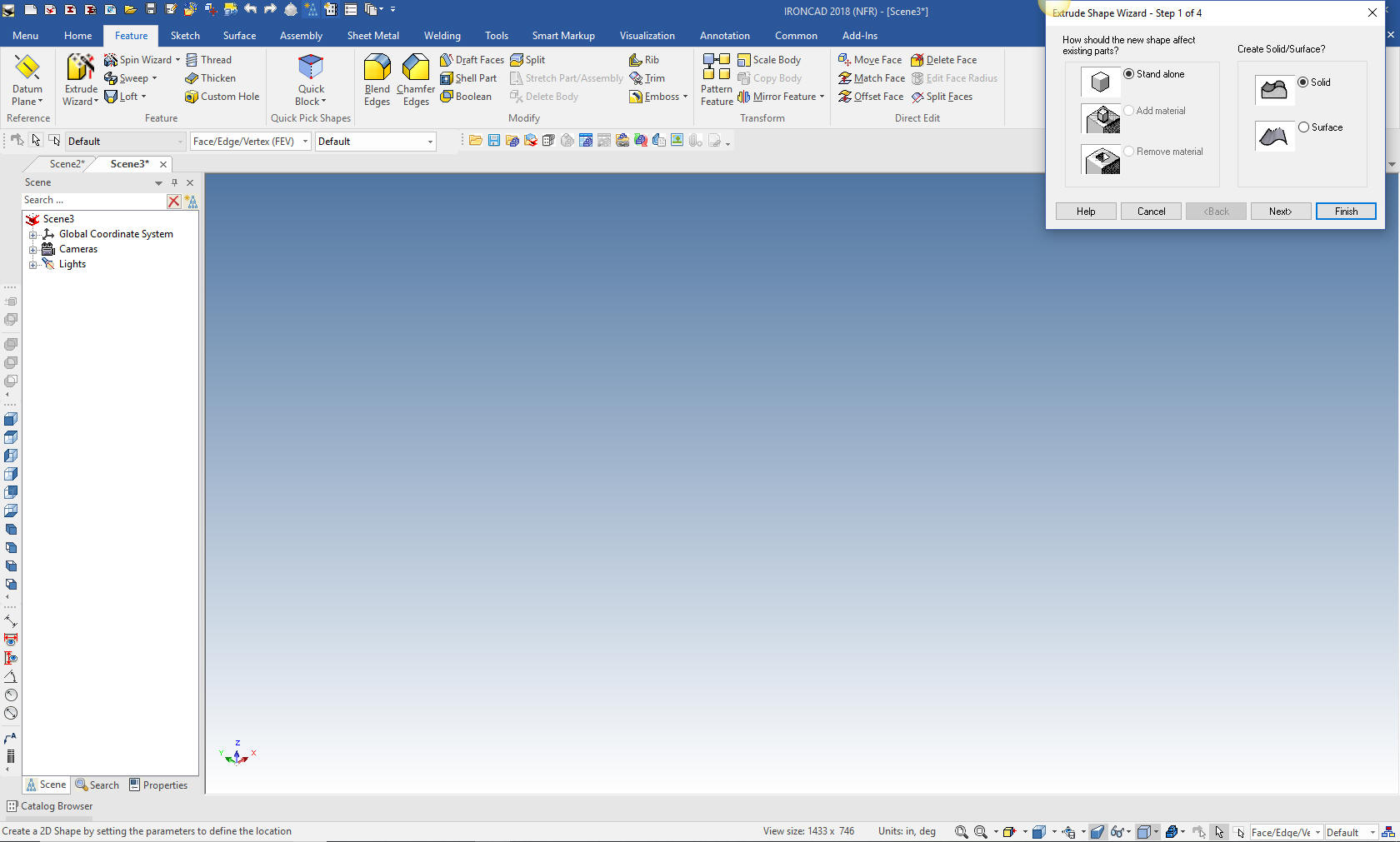
We open a new part.
We select Extrude Wizard (one of the more used function) it
is automatically set to create a standalone part and we set the
depth to 1.50.
It will come up with a sketching plane. I usually set to ISO
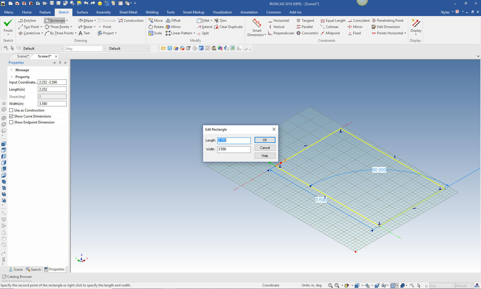
view to work with the sketch. Now for our first sketch. We select
rectangle and with the right button sketch it with two corners. This
will bring up a dialog box to put in the length and width.
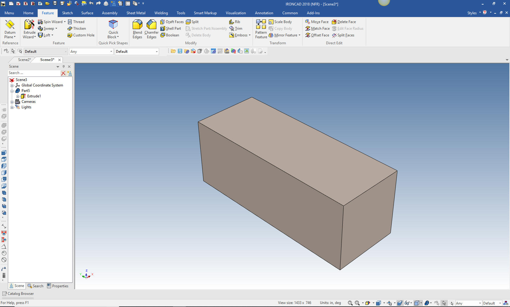
We select finish and we have our block. Remember we set the
height of 1.50 in the first setting of the extrude wizard.
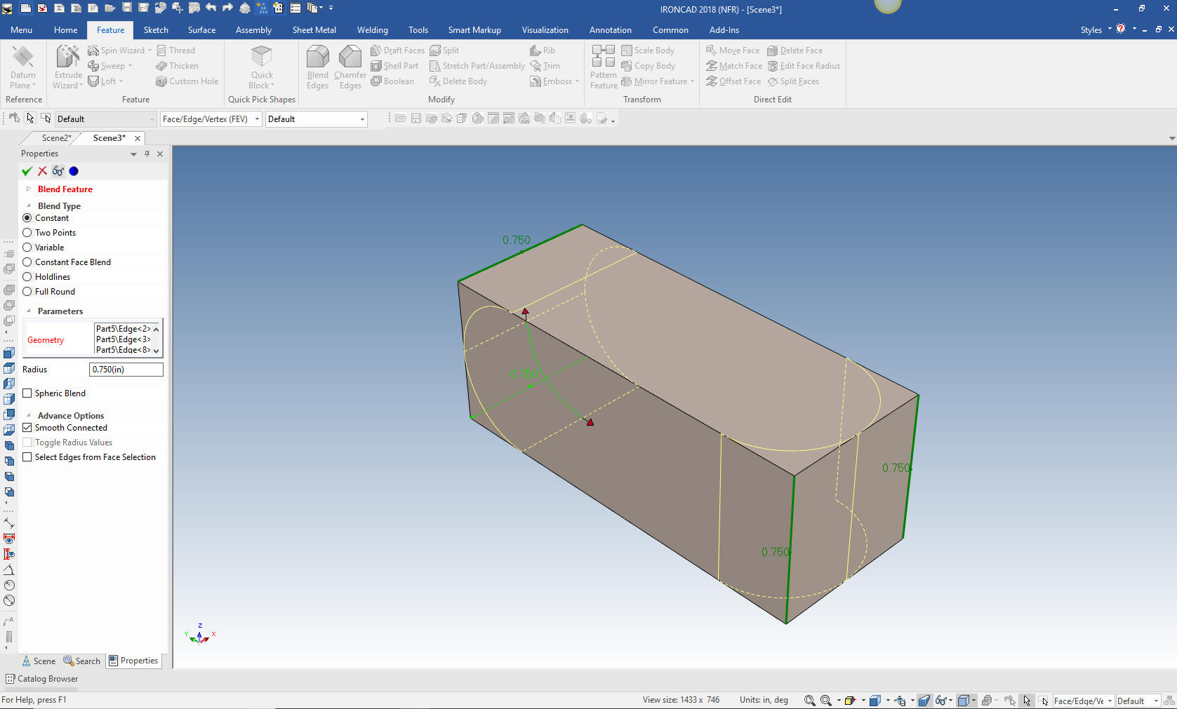
We now put in the .75 blends now to eliminate a step.
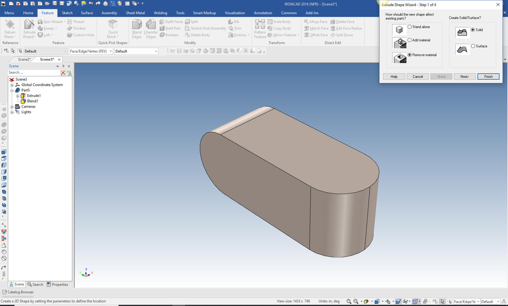
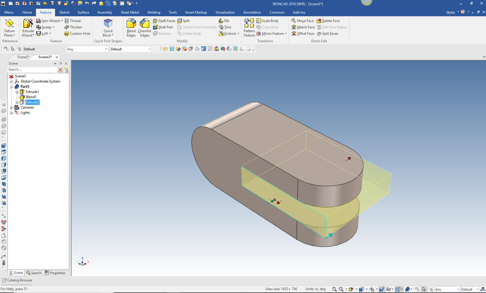
Again we go to the Extrude Wizard and place it on the front face
and set the depth to 1.5 and select remove material.
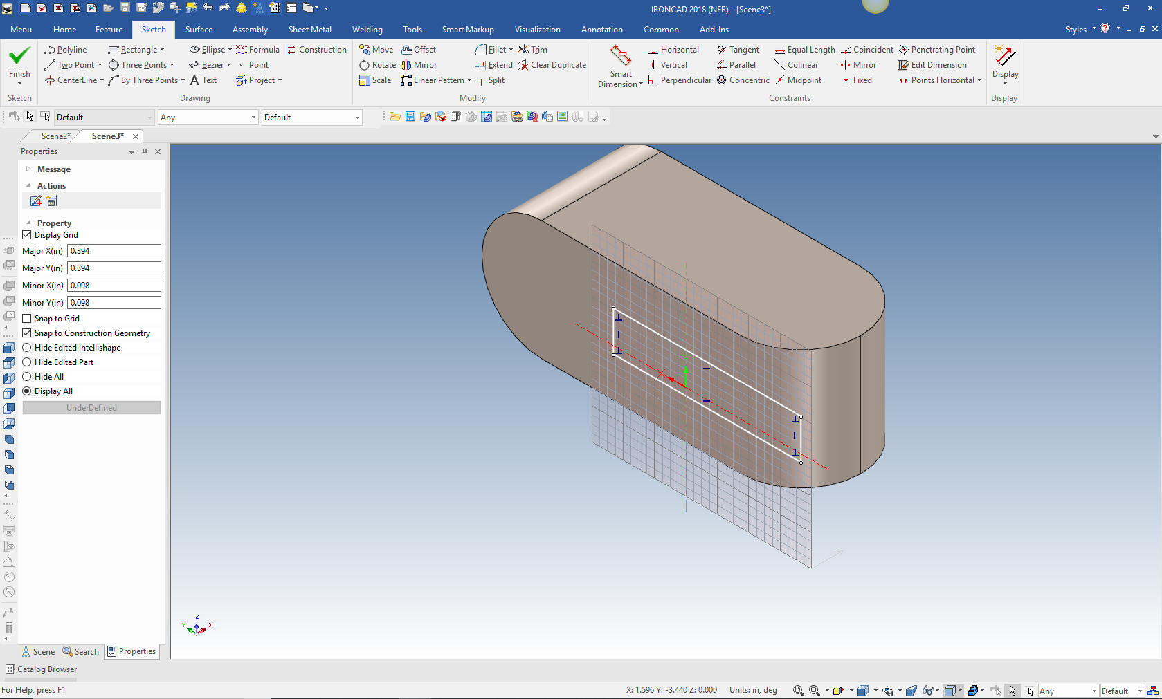
We create the rectangle. No constrained dimensions. Just a few
projected edges, offsets and trims.
We select finish and our extrusion cut is complete in one step.
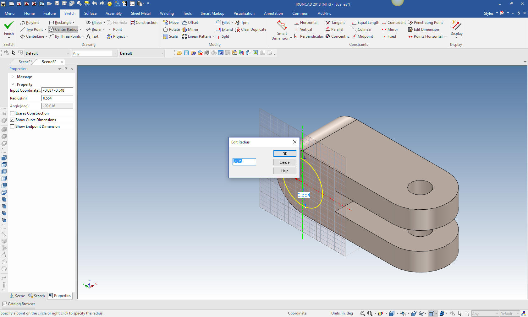
As above I would usually just drag a few hole cylinders but with
this exercise I will again use the extrude wizard. I select center
radius and it automatically recognized the center of the arc and
allows me to set the radius.
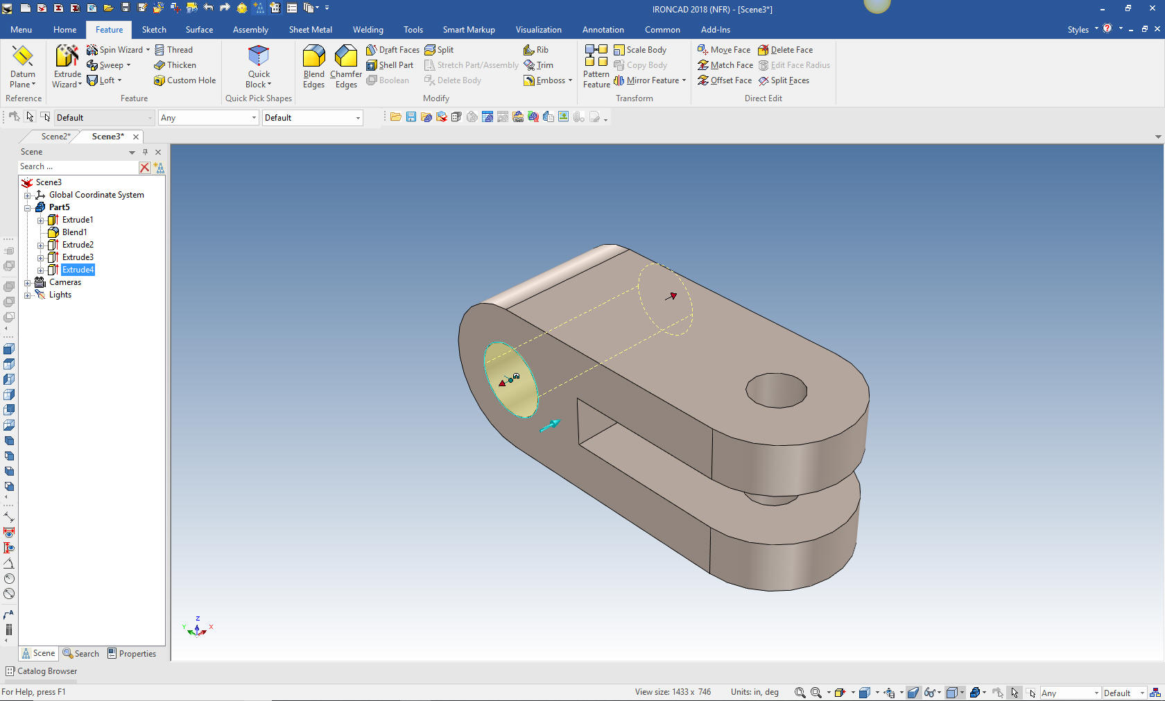
I select okay and select finish and hole is made. No constrained
dimensions. You can see that this is not an intellishape since it
has two little handles on each end. It would have to be edited with
the sketch or direct editing. The intellishape has side handles to
set the diameter.
We are done. Just so much faster and easier. I do this to show
that you do not have to suffer through the constrained sketching in
your own system. Yes, there may be a time you may do some parametric
design and constrained sketching may be required but I have only
used parametrics once in all the years since I have had it available
in 1998.
Now to detail the part. If you are actively converting drawings
to models you have to detail them again. I was consulted on a
complex part and after a short review of the drawing and part I saw
that the fellow had made some blatant errors. Detailing is a very
quick way of checking the part. Yes, time consuming, but not as time
consuming as finding the part doesn't fit.
I am not a
believer in the isometric representations shown in the drawing. If
you cannot read a conventional AID (drawing), you should not be in
engineering.
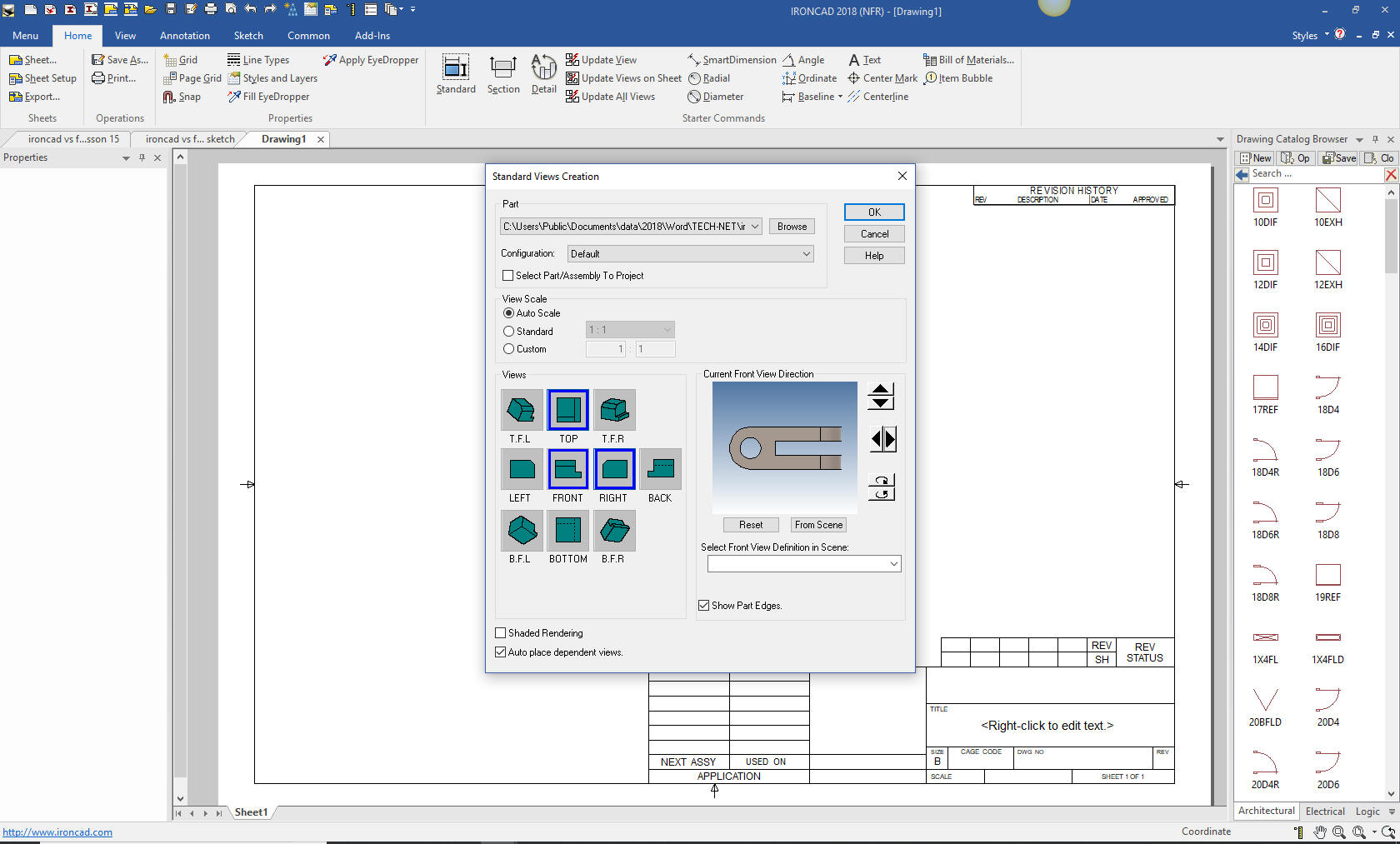
IronCAD has a separate AID module that is tied
to the single model environment . So you can have parts and
assemblies mixed on the same AID file.
It comes up and I set
the views I need.
With that done I proceed to detail the part.
It is very important that you look into
how you or your engineers are creating parts. Streamline
Sketching and Feature Based Modeling is easy to learn and implement.
It, alone, can increase productivity 10X. Now, IronCAD with its unique
history and robust direct edit functionality can increase your
productivity another 5X or more with changes! Again, time is money
in engineering.
More on Streamline Sketching and Feature Based Modeling.
To experience this increased level of
productivity, please download IronCAD for a 30 day evaluation. Legacy
data is no problem, IronCAD can read the native files of all of the
popular programs including the PMI data of NX, Solidworks, Catia and
Creo. IronCAD is a great replacement for the subscription only Autodesk
and PTC products.
Give me a call if you have any
questions. I can set up a skype or go to meeting to show this part
or answer any of your questions on the operation of IronCAD. It
truly is the Ultimate CAD/CAM System.
If you are interested in adding professional
hybrid modeling capabilities or looking for a new solution to
increase your productivity, take some time to download a fully
functional 30 day evaluation and play with these packages. Feel free
to give me a call if you have any questions or would like an on-line
presentation.