Mechanical 3D Modeling Defined
I bumped into an interesting situation that
opened some thoughts on 3D modeling.
I banter with a fellow 3D CAD user, on how to
model. He is one of the best 3D modelers in the world. He is always
throwing something at me about modeling speed.
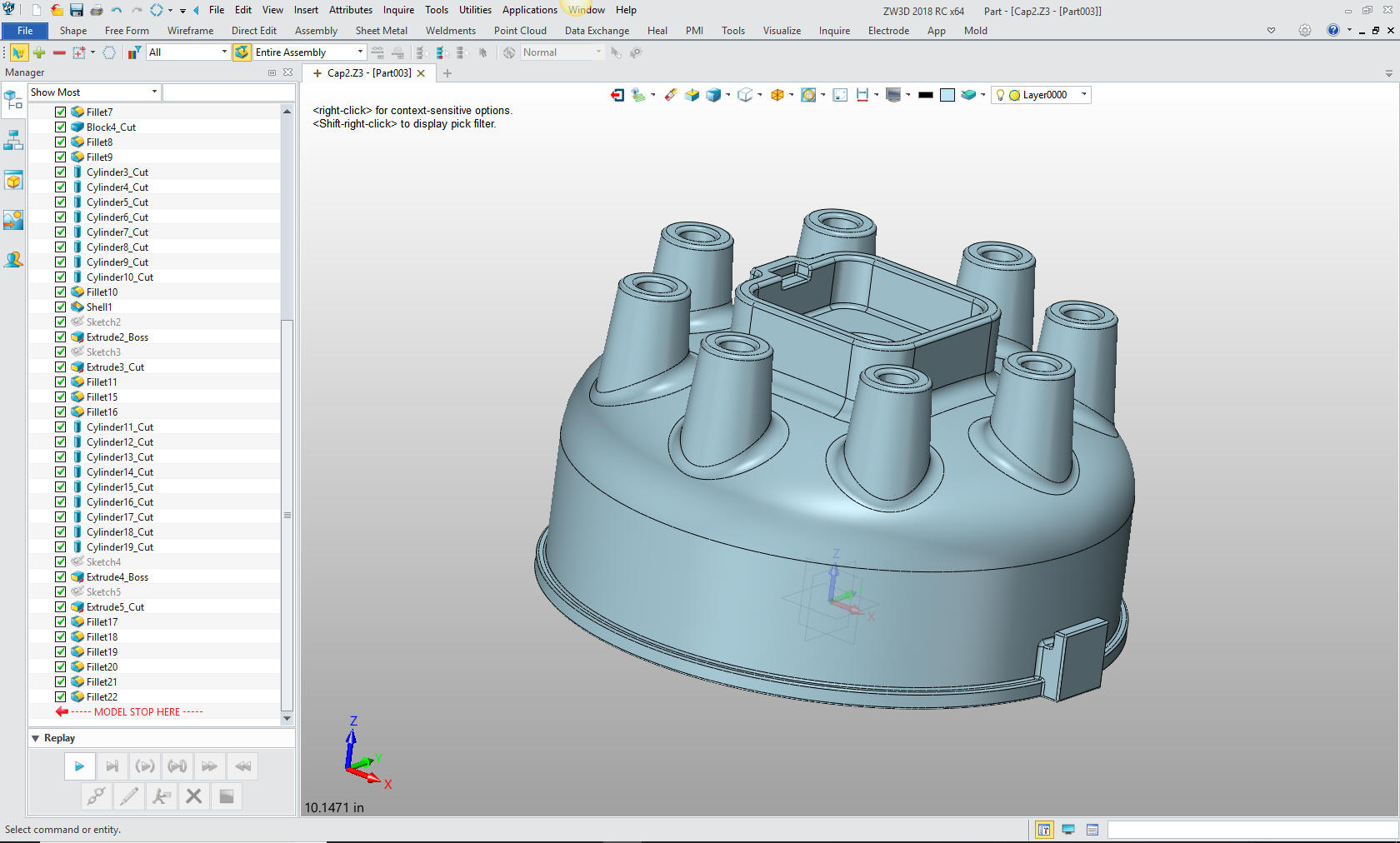
He threw out a model that he did on the fly in 3 minutes or
so. He uses ZW3D and I use IronCAD. It is great fun. I followed up with
my version in about the same time, but I had to scrutinize his model.
ZW3D
He created another model. Now the big difference
between him and me is that he is incredibly creative and can create
models on the fly. I have never seen anyone do this.
The model was a much more complex and I could not
easily scrutinize it. So, I decided to detail it and not only model it
but use it for a training model.
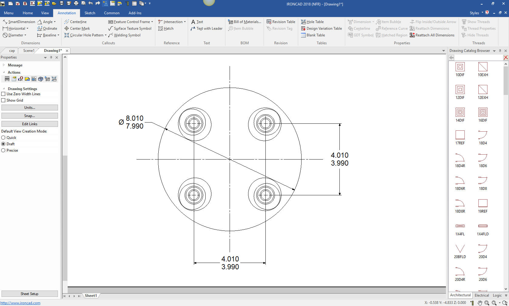
Here is where I stopped and decided not to continue.
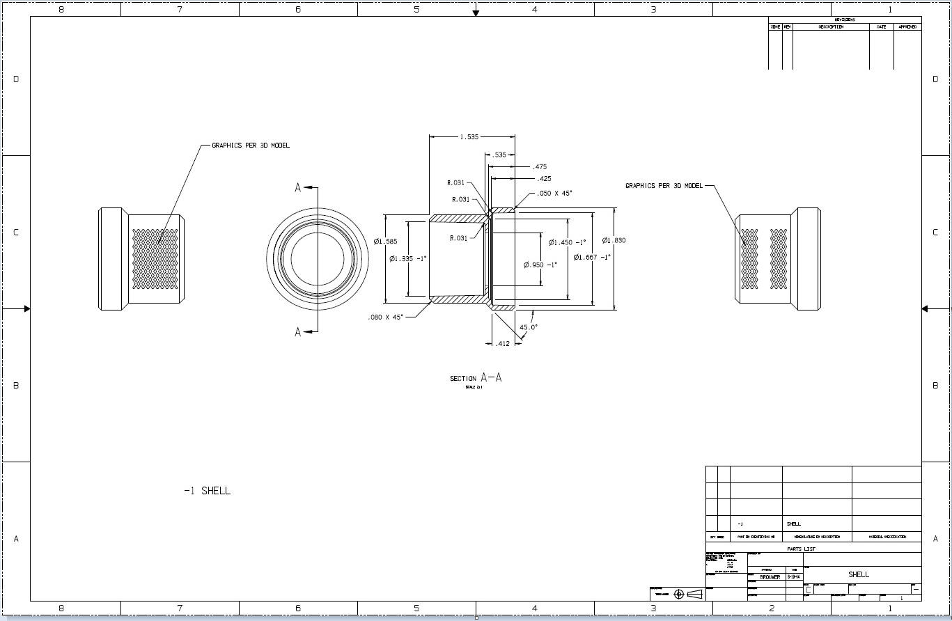
(ZW3D has integrated drawings, how cool is that)
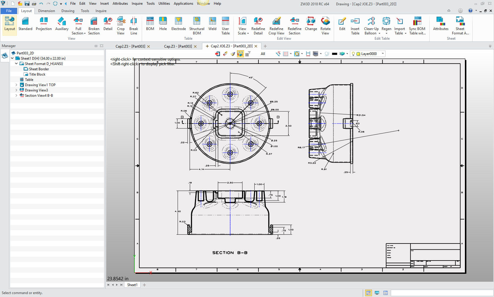
Now look at these dims. Did I want to create this sketch? Not really.
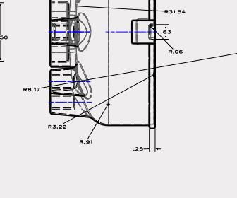 When
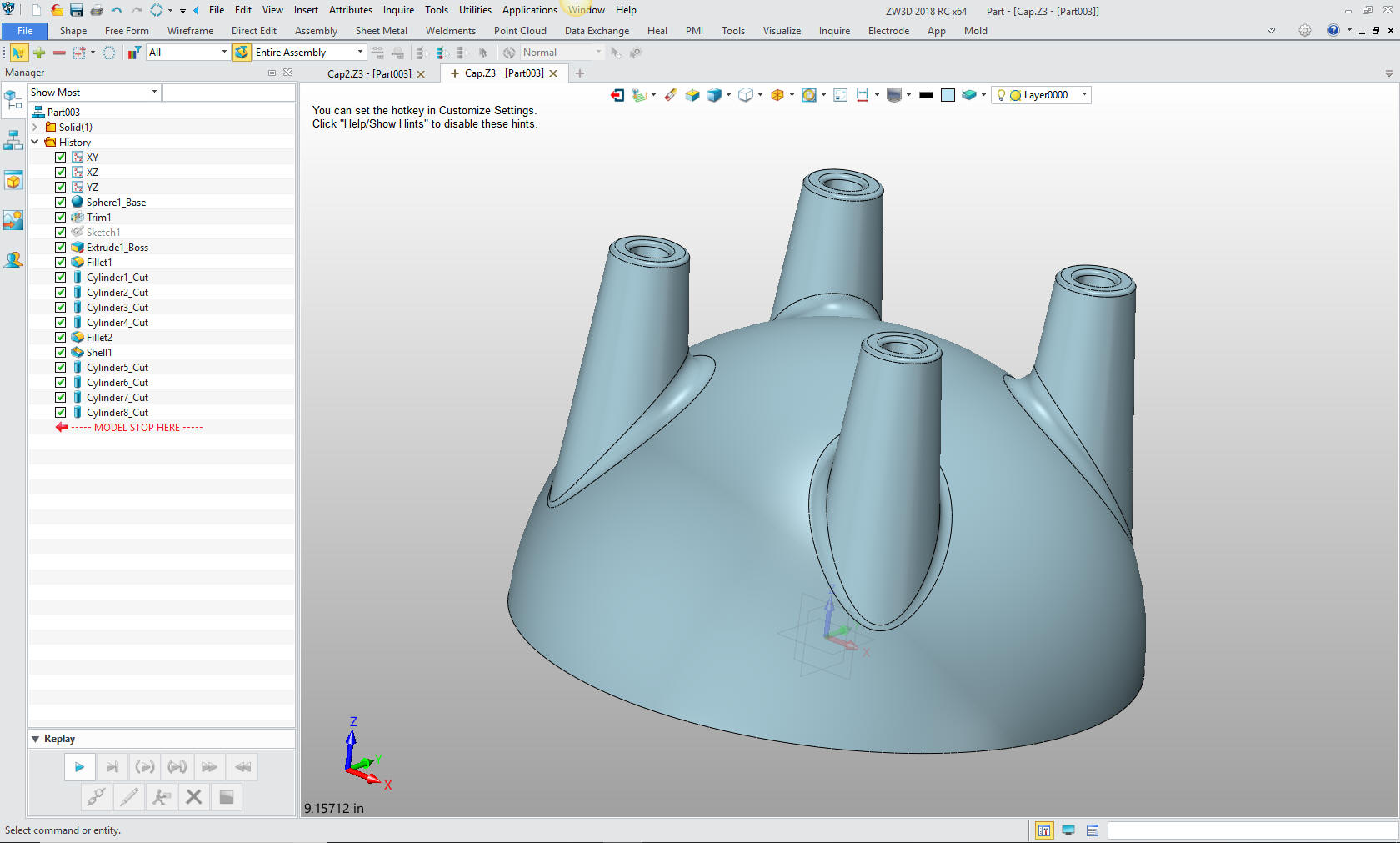
I got to this one feature and detailed it , I quickly saw that this was
not done with a sketch and revolve. I scratched my
head and looked at the ZW3D model. I realized he create this shape with
an arbitrary dome. Now, he was just having fun and this was not a
production part, it was just an exercise in 3D modeling
When
I got to this one feature and detailed it , I quickly saw that this was
not done with a sketch and revolve. I scratched my
head and looked at the ZW3D model. I realized he create this shape with
an arbitrary dome. Now, he was just having fun and this was not a
production part, it was just an exercise in 3D modeling
An example of this situation would be with Boeing having 2 completely incompatible 3D CAD packages, Catia 4 and Catia 5. I am sure many of the Catia 4 parts would have to be modified since all the airplane models were created in it until the 787. All CAD was done in Catia 4 until the release of Catia 5 in 1998 and continued for many years. Sadly, the transition to Catia 5 was fraught with problems. Catia 5 could not modify Catia 4 parts directly. I am not sure how Catia 5 read Catia 4 parts, today, the last time I was involved it was with STEP files. So, they would have to detail the Catia 4 models and recreate them... maybe?
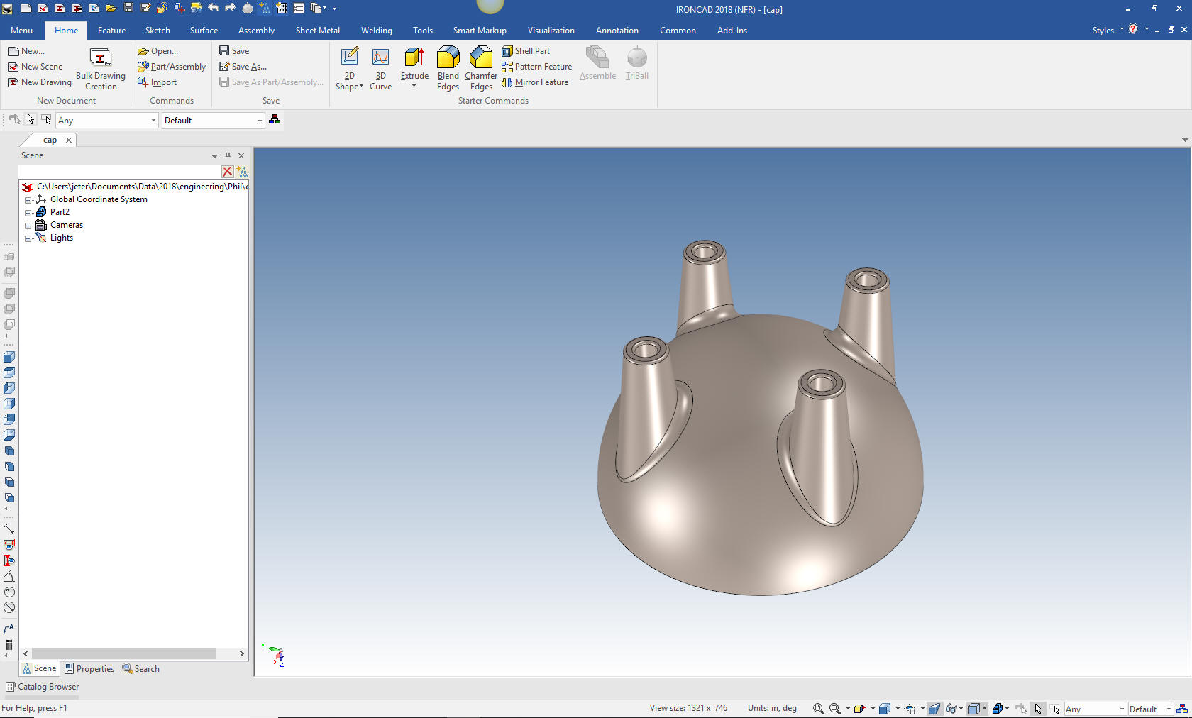
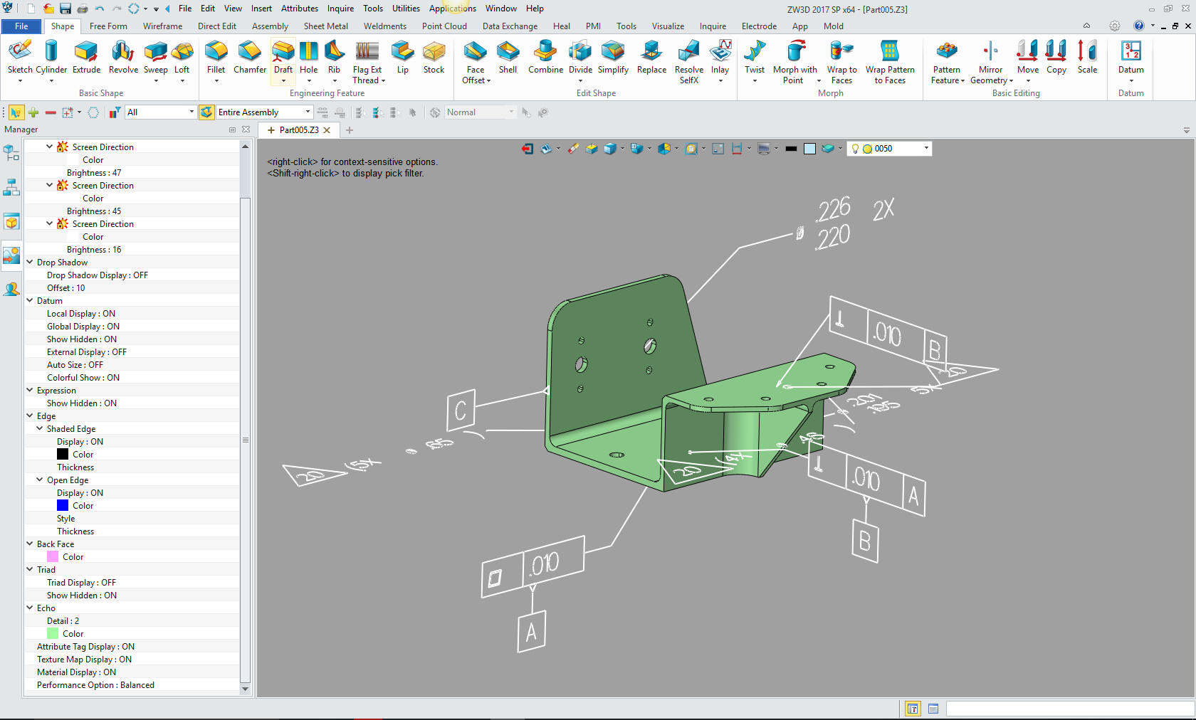
Back to the modelSo lets see how this model was created. You can see he just used the dome option in ZW3D. ZW3D is miles above most 3D CAD systems with its highly functional hybrid modeling.
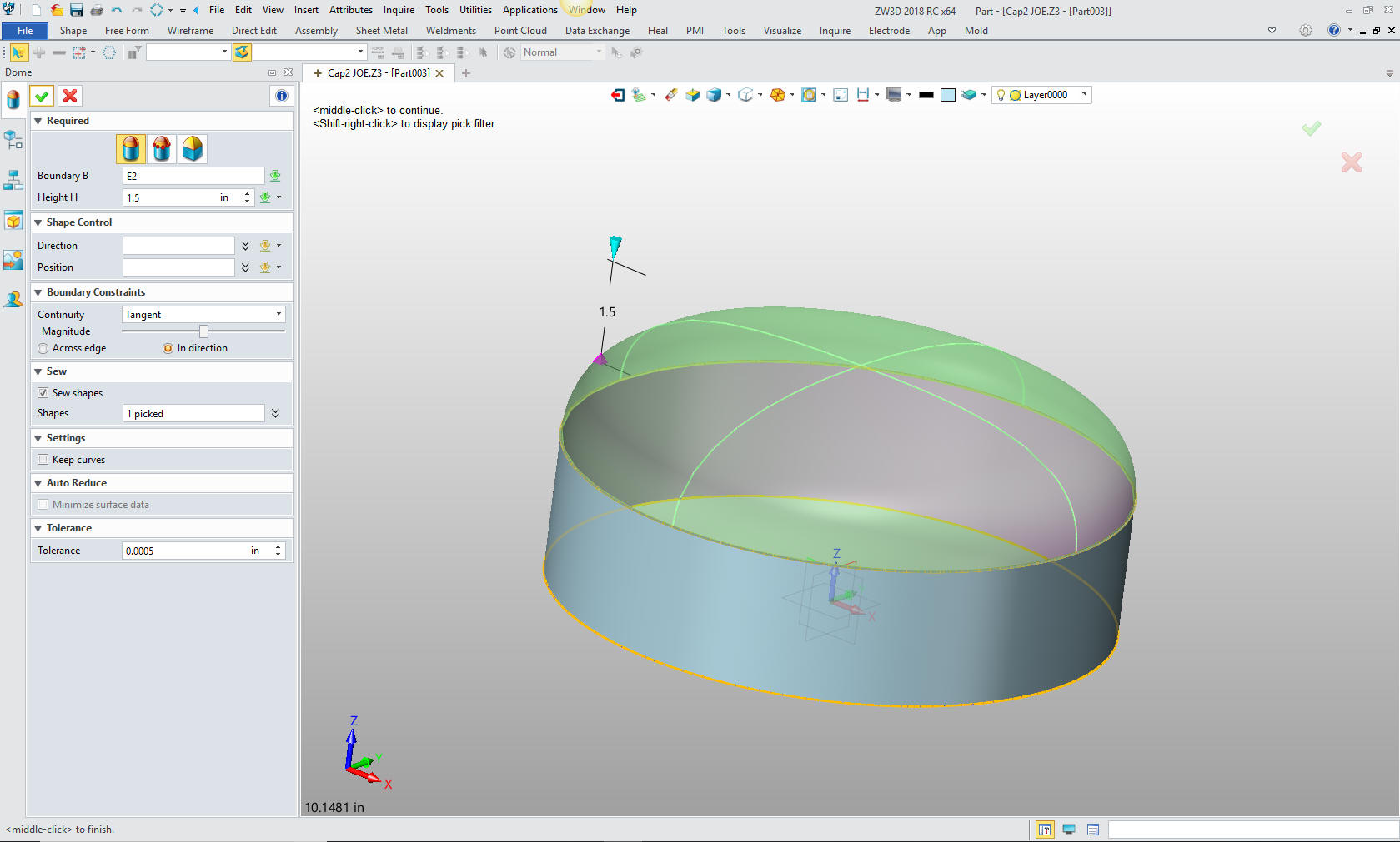
Could have I put the similar dome in IronCAD? Probably, but that was not my concern at this time. I had ZW3D and the model available to scrutinize. But what if I didn't?
I realized something about the direction of
3D modeling.
If I did this part, it would be with mechanically
defined features, playing or not, with a precise sketch and revolve. It is just the way I design.
In the beginning 3D CAD, including Pro/e (Creo), was promoted as a way to create faster drawings. We would create the 3D model and detail instances of the part in different views in the drawing module. We could add annotation and the drawings were done to the existing drawing standards. The programs were focused on standard design. Remember only draftsman used CAD in the beginning. Engineers didn't widely transition to 3D CAD until it moved to the PC at the turn of the century.
The 1980's - 3D CAD - The Beginning
I complain about those that only do constrained sketching, but with his concept you are forced to do true mechanical design. Yes, i know you can screw up a model with sketches but mostly things are done correctly.
But, it mostly demands that you do mechanical
design that can be easily detailed.
I push Streamlined Sketching that uses
horizontal, vertical and angled lines and use offsetting and trimming to
create my sketches. No constraints. But still mechanical design.
Good sketching mostly leads to good duplicable mechanical
design.
Enter Direct Editing
I used 2D/3D wireframe, surfacing and Boolean
solid modeling in the beginning. It formed my modeling techniques, the
reason for Streamlined Sketching.
Feature based direct editing showed up with
IronCAD in 1998 and soon CADKEY also had implemented it. In the
beginning Boolean modeling was very primitive. You would split a model
and many times you could not join it back together. But the ACIS and
Parasolid modeling kernels were constantly improving.
With the introduction of SpaceClaim and Siemens
Synchronous Technology direct edit finally matured to an acceptable viable modeling
process. CADKEY and IronCAD already had it so I was a bit ahead of the
game. CADKEY was a direct edit only package and I feel without history
you only have half of the 3D design functionality. IronCAD is the only
truly integrated history based/direct edit 3D modeler. You use both
modeling techniques in your design process.
Now I am a mechanical design draftsman that believes in completely detailing my parts and delivering an AID (Associated Information Document (drawing)) along with the 3D model as a reference document. I do this to check for errors or many times a better design. I find this step invaluable to eliminate problems later.
So, my direct editing is always focused on
keeping the part
something that can be easily detailed. Just the nature of a manual based design
draftsman.
Now, I have referenced textures and text graphics
per the model.
Direct editing has not been widely adopted due to
the poor implementation in the Pro/e (Creo) clones that have not made it
effectively available in the design process.
But soon the 3D modeling paradigm will change and direct edit will be a viable function use along with history based design in the design process. This will open the door to incredibly flexible modeling especially when modifying the 3D model increasing productivity 5 to 10X.
Is 3D CAD Productivity an Oxymoron?
Will the concept of mechanical design in the
sense of precisely defined documentation be used?
Now, you can also add the introduction of
surfacing in your design process. While you can reference the process,
you cannot precisely document it. When you think of advanced surfacing
you think of an auto body. It really is not much different. Since the
shape was not based on drawings but a clay model.
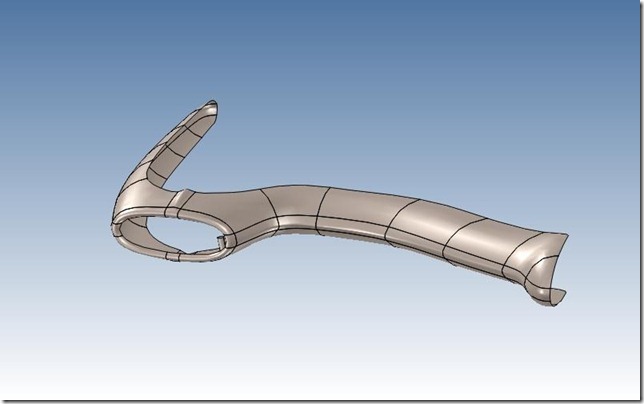
Here is a reverse engineering job on a 1959
Corvette bumper. I had some problems, imagine what the pattern maker
went through?
MBE (Model Based Enterprise)
Are we going to the level where the model cannot
be defined by dimensions and the 3D model is the only document?
Personally, it reminds me of a time I was under
contract at Williams International.
The chief draftsman (a field promotion) demanded
we use limited tolerances for all dimensions. He said we will not have
any non-thinking tolerances.
I was a young draftsman and I told him if we did
that all dimensions become important.
Why?
In those days we had UOS (Unless Otherwise
Specified), we would use decimal places to show the importance of the
dimension. X.XX = +/- .03 X.XXX = +/- .010. Now that was at Boeing and
it may be different for different industries. That was when they turned
knobs to machine. Today, any machining can hit .005 in CNC so I suppose
it would change the priorities in design and tolerancing.
T
This added a new level of complication to the
process. The cost of the parts would soar. Imagine each dimension would
have to be calculated to find the basic dim? Very short sighted, that
Chief Draftsman.
Now, we move to freeform 3D modeling and this
concept is reversed. Virtually no way to effectively review the part.
Just directly model the part with no restraints?
With manual drafting all of our circle templates and scales were were in eighths and tenths. Manufacturing worked on the same basis. We designed to standards.
No detailing Required?
Now, this is a question we must ask.
Are we moving toward non-thinking design?
Enter Generative Design
I am not going to do a definition, they seem to be a bit proprietary, you can google it for yourselves. Autodesk seems to be deep into this technology. I will just show this image.
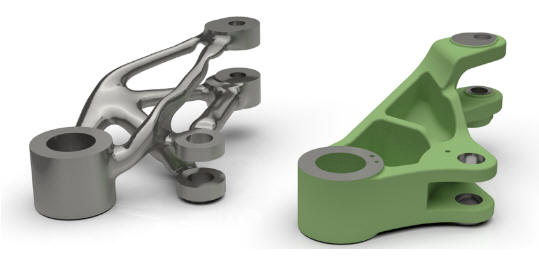
One of the problems I instantly saw was documentation. I suppose besides the final model you would have to also include the original model with an AID that would define the software and the necessary steps to create the final model plus material, manufacturing process, finish, etc.
This actually looks like a legal nightmare.
|
TECH-NET Engineering Services! We sell and support IronCAD and ZW3D Products and provide engineering services throughout the USA and Canada! |
If you would like more information or to download ZW3D or IronCAD
With 53 years of experience in engineering, 17 years in manual board design as a contract engineer, 35 years in 3D CAD sales, support, training and providing engineering services, I have a high level of understanding of today's 3D CAD engineering world. For many it is in chaos. If you are having problems or just interested in this subject please feel free to call and we can discuss them. There are so many simpler solutions available that will save you time and money.
 Please visit our Viewpoints for more articles on our industry that may interest you.
 See you online.
Joe Brouwer
206-842-0360