Awhile ago I got a ZW3D software request
from Phil. He was interested in the purchase options. He downloaded ZW3D
and within a month he was ready to purchase ZW3D Standard. He was highly
interested in the surfacing capabilities of ZW3D. This was the beginning
of a new adventure in 3D CAD.
I quickly realized Phil was not just some CAD
jockey he is also a professional Tool & Die Maker, Designer and Engineer.
Being a draftsman, Phil and I have quite a bit in common about standard
documentation and manufacturing. So not only will Phil offer tips on
modeling but in sharing his deep 3D knowledge as it pertains to engineering
and manufacturing.
Phil is one of the two highest skilled CAD professionals I know. The
other is Selcuk Ozmumcu, both not only use CAD in their jobs but use it to
model many other things as a hobby! It is interesting that both use ZW3D.
They use it because if offers the highest level of design capability at a
price we can all afford. ZW3D matches the highest end package like NX, Catia
and Creo, in performance without the the added over head of complex
operation, and system management and requirements but much more cost
effective at $3000,00 and $1200.00 Annual rental.
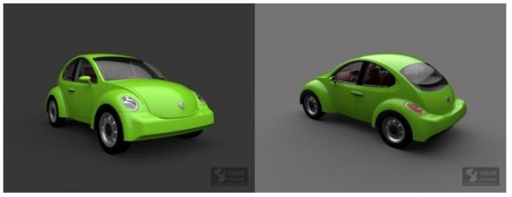
Selcuk is a
Industrial Designers, so offers a much different experience than Phil.
Please take a look at some of his work!
In this first part of the container tutorial, I want to show how to easily
create panels on a curved surface in ZW3D 2021. The focus of Part1 is to
show how the Unfold to Surface Tool can make hard tasks like this very easy
to achieve.
You will notice that I skipped over the basic tasks in ZW3D as tutorials for
those tasks can be found in the getting started with ZW3D in the tutorials
section.
Step1: After you create your part file, select the Cylinder Tool, and
set your location and dimensions as shown below.
Step2: Next we are going to select the top and bottom edges of the
container and add a 6″ fillet.
Step3: Now we want to select the Unfold to Plane Tool, select our face
then select the Plane/Datum we want to unfold too.
Step4: What’s nice about unfolding the curved surface is we now have an
accurate flat surface to work with. Doing a layout on this surface is very
easy. Hide the solid container so we have a clean unobstructed viewport to
do our layout.
Step5: To start our layout we will create a sketch on the unfolded plane.
Step6: Next we are going to create some references so we can do our
layout. The Reference Tool is very handy, just make sure you don’t abuse it.
Step7: We want to add points equally spaced across the edges. There are
many ways to do this, I am only showing you one possible way.
Step8: Next we need to constrain the points so they don’t move when we
add dimensions off them.
Step9: Next we will start blocking in our panels and dimensioning them.
Step10: Continue blocking in the panels and dimensioning them.
Step11: Add 1″ corner fillets to all the panels using the Fillet Chain
Tool.
Step12: Create our 1/4″ panels using the Extrude Tool.
Step13: After creating our panels we need to wrap them back around the
solid model. We use the Wrap to Faces Tool.
Step14: Checking our work.
Step15: Next we need to shell our solid to turn it into a container. For
this we will use the Shell Tool.
Step16: Now we are going to cut the pockets for all the panels to set in.
For this we will use the Remove Shape Tool.
Step17: We have to remember to add tolerance gaps for our panels so when
they are manufactured they will fit into place. For this we will use the
Face Offset Tool.
Step18: Next we need to create the lip and the cutout for the panels. The
Offset Tool is very good for this.
Step19: We want to copy the faces so we can use them to cutout the
container.
Step20: Now we want to trim the copies to the correct size.
Step21: Remove the outside of the trimmed panels.
Step22: Next we want to thicken them so we can use them as solid cut
pieces.
Step23: Cut the inside cutouts from the container.
Step24: Add 1/16″ fillets to all the sharp edges.
Step25: Again we will add 1/16″ fillets to all the sharp edges.
Step26: Next we will check our work.
Final Model: You should have a container with panels like this.
Cheers,
Phil Procario Jr.
You can contact Phil directly at Phil@tecnetinc.com