3D Modeling Techniques
ZW3D vs Creo Lesson Three Primitive
Shape Design Streamlined Sketching/Feature Based Modeling
Modeling note:
It is funny,
you may not realize how you model because you have many ingrained
processes from the past. I have been doing Boolean (direct edit)
design since the beginning of solid modeling in CAD. As I have been doing these comparisons I
realized that I design in shapes. ZW3D has primitive shapes and
robust direct edit functionality. I look at the drawing and pick out
the basic shapes of the part instead of creating a sketch. You can see that in this part.
I saw some Fusion 360 exercises online and
I decided to compare ZW3D. It quickly turned into a study in
modeling techniques. I have created fifteen "ZW3D
vs Fusion 360" six
"ZW3D
vs Solidworks" and
"ZW3D vs Creo" lessons to
show the difference between ZW3D and the two programs and my
modeling techniques. I found the Fusion 360, Solidworks and Creo
presenters wasting massive amounts of time with overly complex
constrained sketching procedures. I was so unimpressed that I
decided to model the parts or assemblies showing my modeling
techniques plus ZW3D's superb design system.
Many of these modeling techniques can easily
be implemented even within the most Solidworkish of systems. I call it
Streamlined Sketching and Feature Based Modeling. Please review a few of the above IronCAD vs Fusion 360, Solidworks
and Creo
lessons, there are some very stark differences.
Please watch
a Creo user model this part!
With all the
tedious constrained
sketching for this simple part for the Absolute Beginner, you can imagine a
complex part?
Creo
Parametric Advanced 3D Modeling Tutorial of Engine
While creating 3D models from drawings is the very best
way to learn 3D CAD and maybe some design techniques it does not
expose the designer to the design flexibility necessary in design. IronCAD is all top down due to the single model environment.
Creating mating parts is a cruise. But modeling is just one aspect of a
well designed productive 3D CAD system.
Creo
is a marginal 3D CAD system based on the dated Pro/e history
based modeling system released in 1988. I sold Pro/e years ago
and found it not productive enough
for our engineering department. We use what we sell. That gives us
the experience to effectively support our user base.
I would do a
video, but I really am not good at it. So I will show you step by
step. I will try and get ZW3D support to create one. They are
very good.
The modeling technique is hugely responsible for
the level of productivity. Those of you that are only trained in the
sketch, sketch, constrain, constrain world are truly limited by not
using the freedom of feature based design, that is available in even
the most Solidworks-ish of CAD systems. If your
designers are designing in these very unproductive and time
consuming processes it might be time to review your standard design
processes. Don't have any do you?
These lessons have actually turned into exercises in
modeling techniques as compared to showing a more productive CAD
systems. Again, I say, there are many different ways to model a part.
I see with my exposure to direct edit modelers like CADKEY, I
rarely sketch like you see the Solidworks fellow doing. I have always
created my basic sketches by mostly creating offsets and extending
and trimming or. It seems to be much easier. I never put in a fillet that
can be created later. What do you think?
Since ZW3D
is a sketch based product with a primitive shape option I will
create the model in both processes. The sketched based model will be
done with StreamLined Sketching to show the incredible simplicity
and productivity over the de facto constrained sketching.
I
create a new Part/Assembly file.
Note: When doing production
design you can use the Multi-Object file to create a part file under
a top file. You then could keep a legacy of modifications or similar
parts in a single file
Modeling with Primitive Shapes
We are already in millimeters so lets get started.
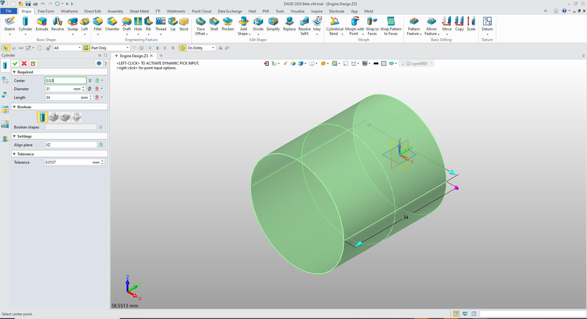
Again
I instantly differ from the Creo presenter by inserting a
primitive cylinder at X0Y0Z0 and sizing it.
Note: Pro/e clones have been starting with the sketch for almost
30 years. Even today the sketch is the only option in most programs.
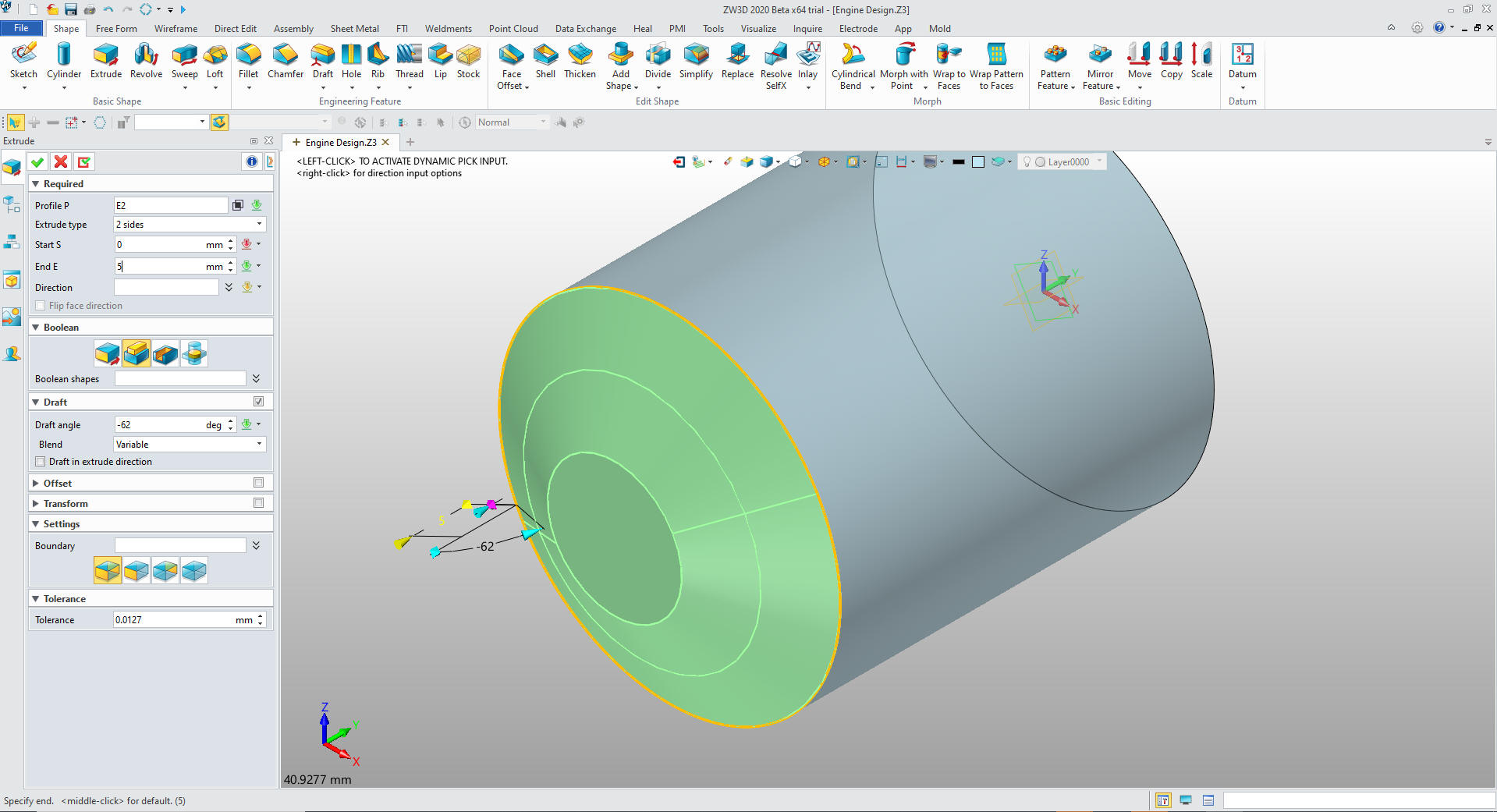
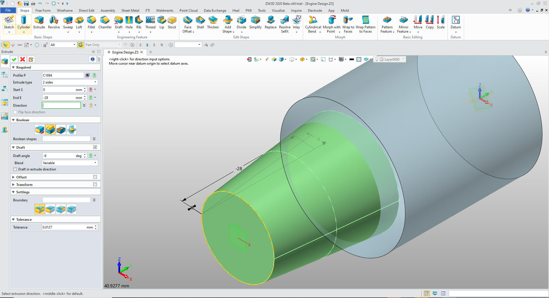
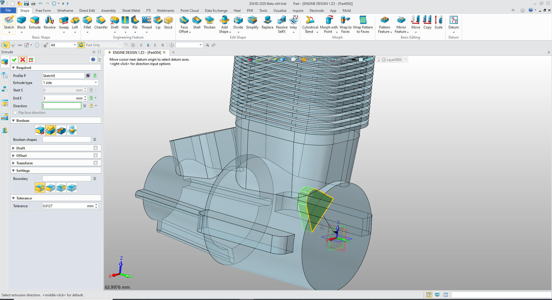
We create an extrusion using the face of
the main cylinder and setting the length and draft and set to add
We have to use extrusion since the primitive cylinder has not
draft capabilities. I put that in for a new enhancement.
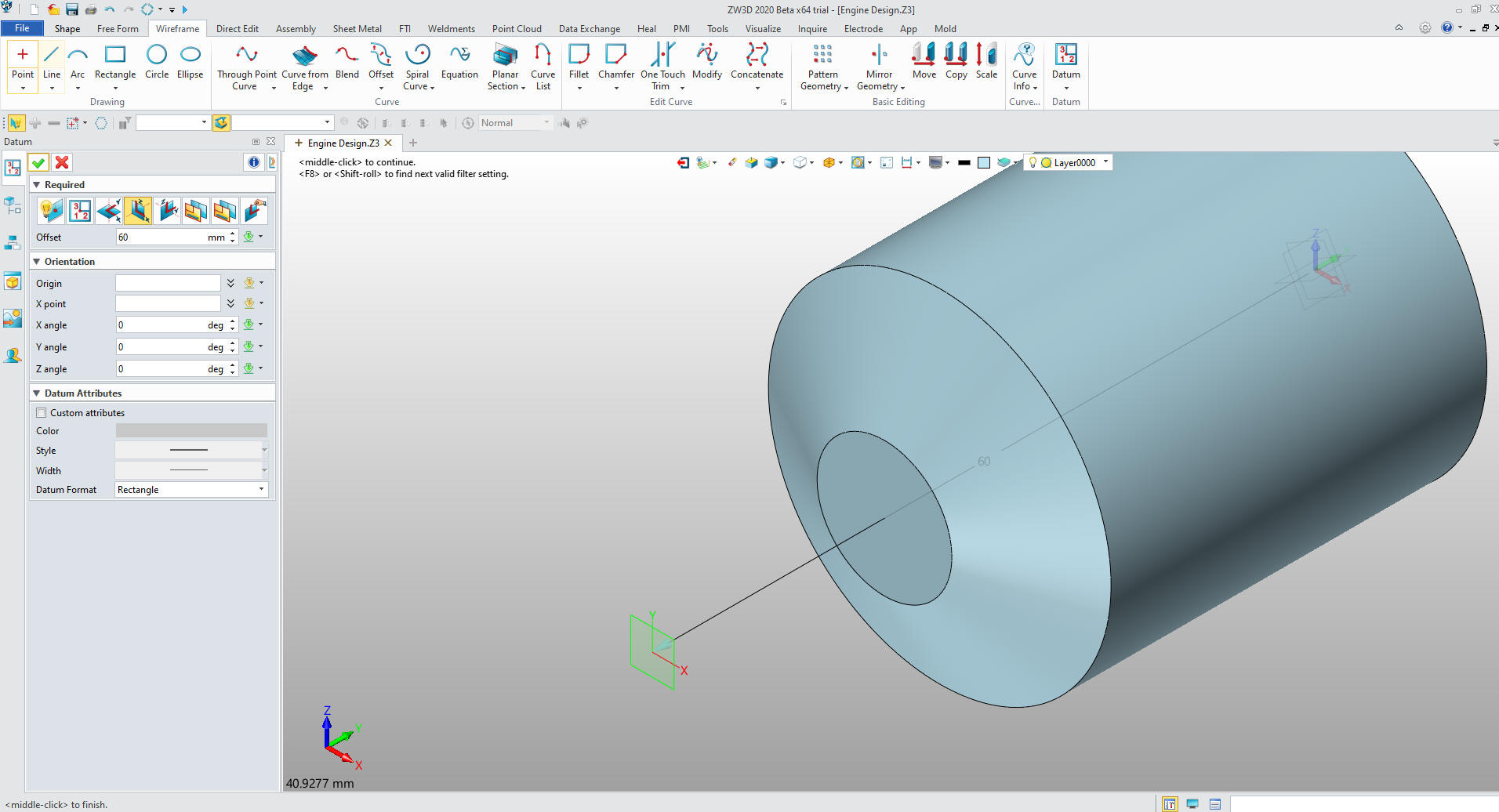
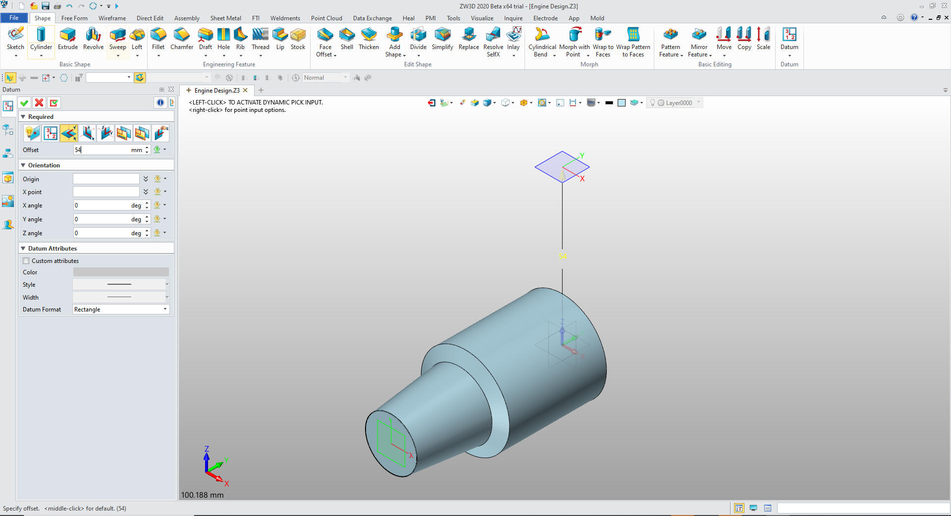
We create a plane by offsetting 60mm.
We
don't have to create a sketch, just go to the wireframe menu and
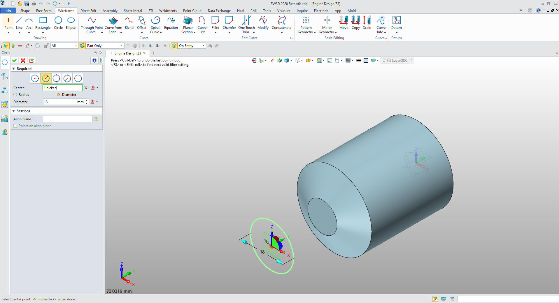
create a circle on that plane.
We use
the extrude command to set the diameter and length, we set the draft
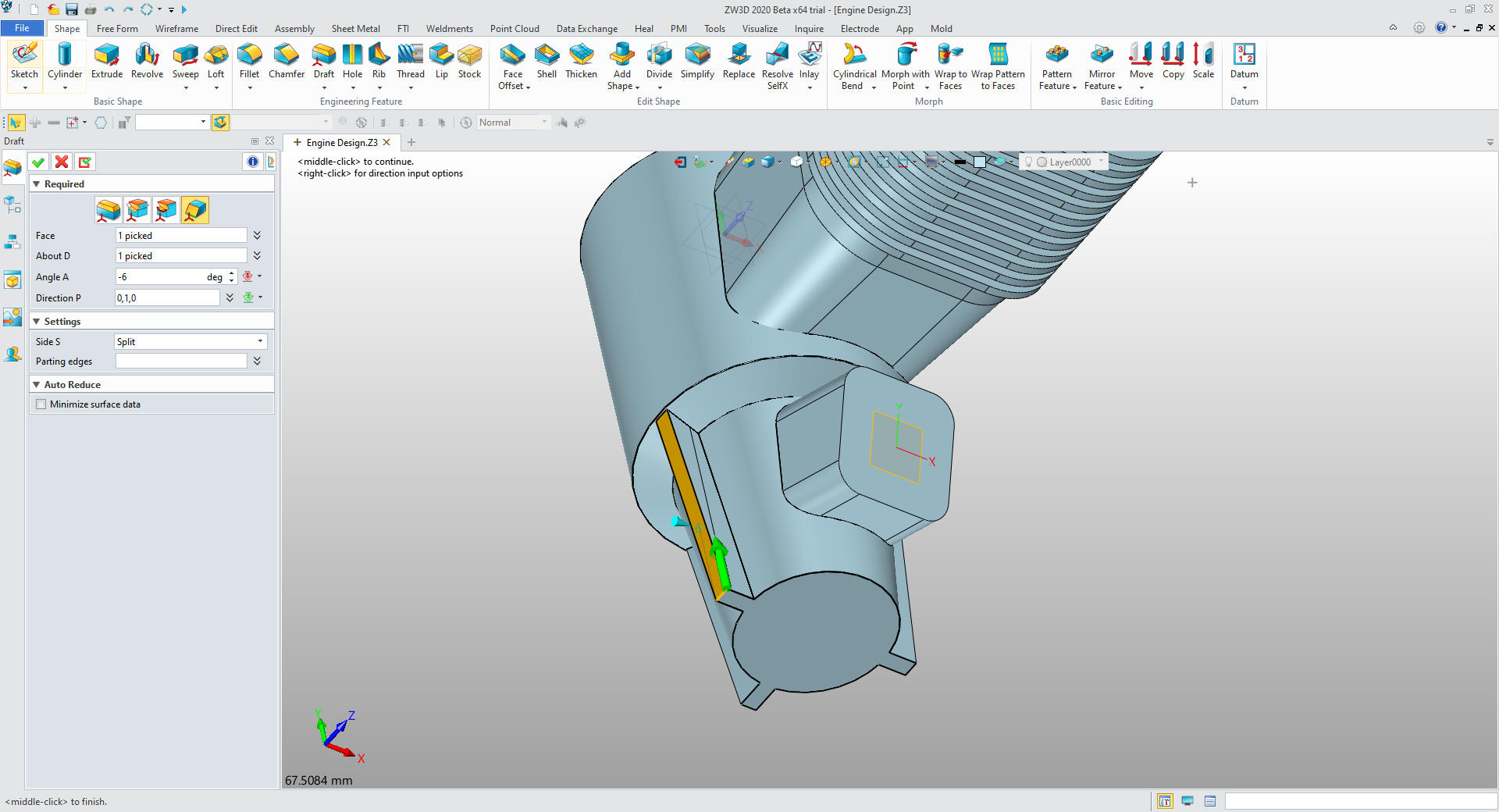
to 6 degrees and set to add.
We no
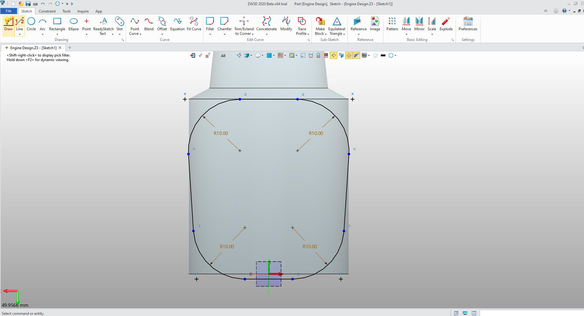
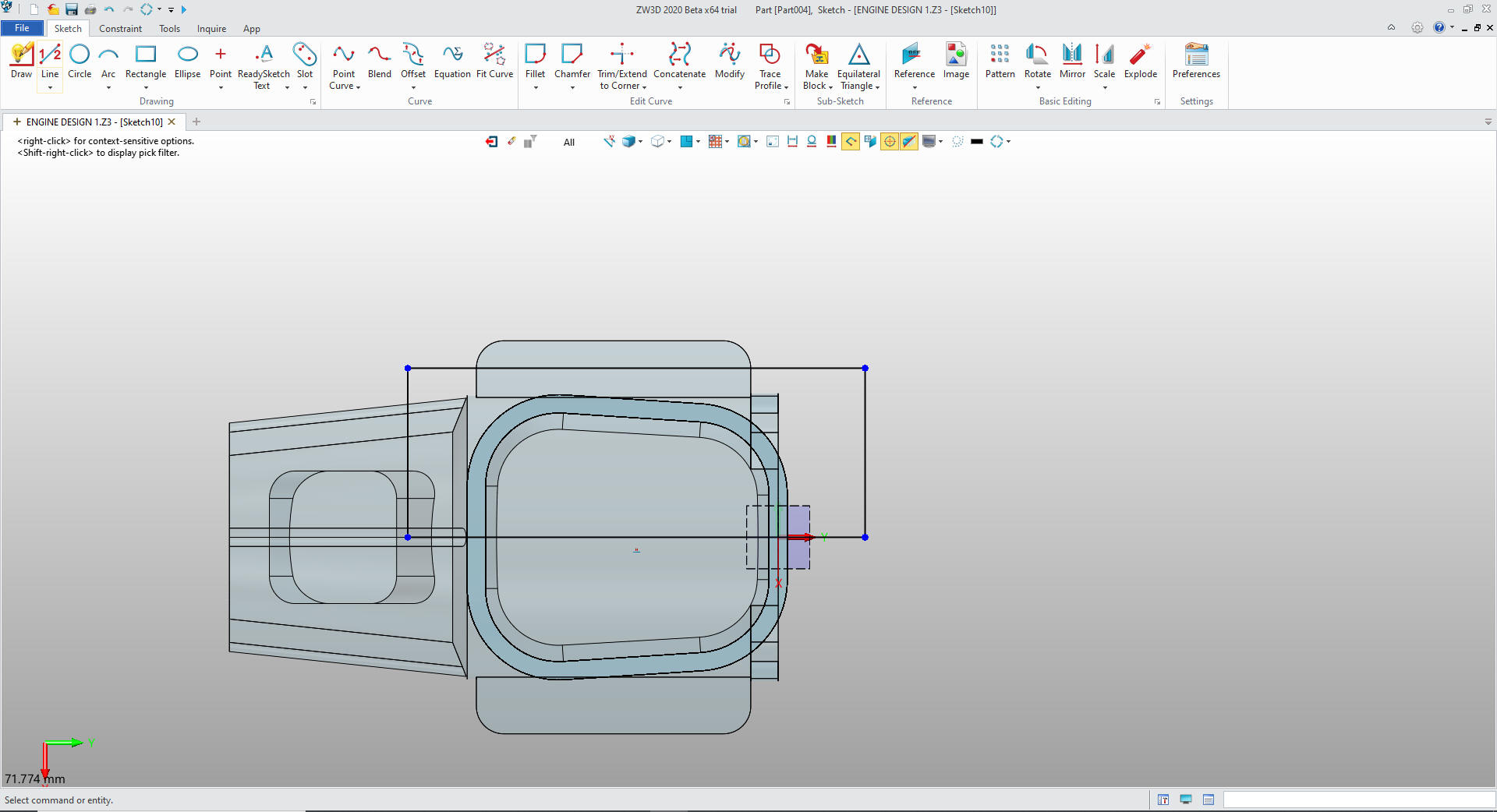
set up the cylinder block by offsetting XY plane
We
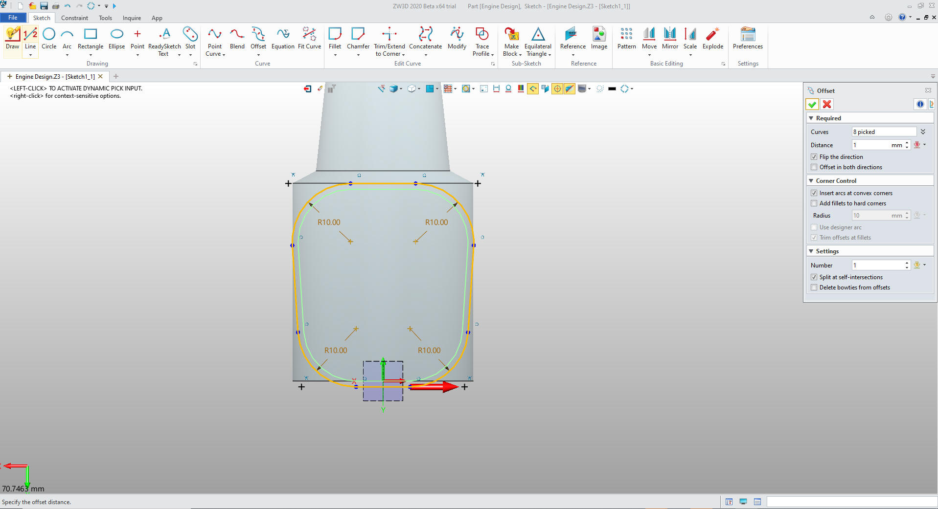
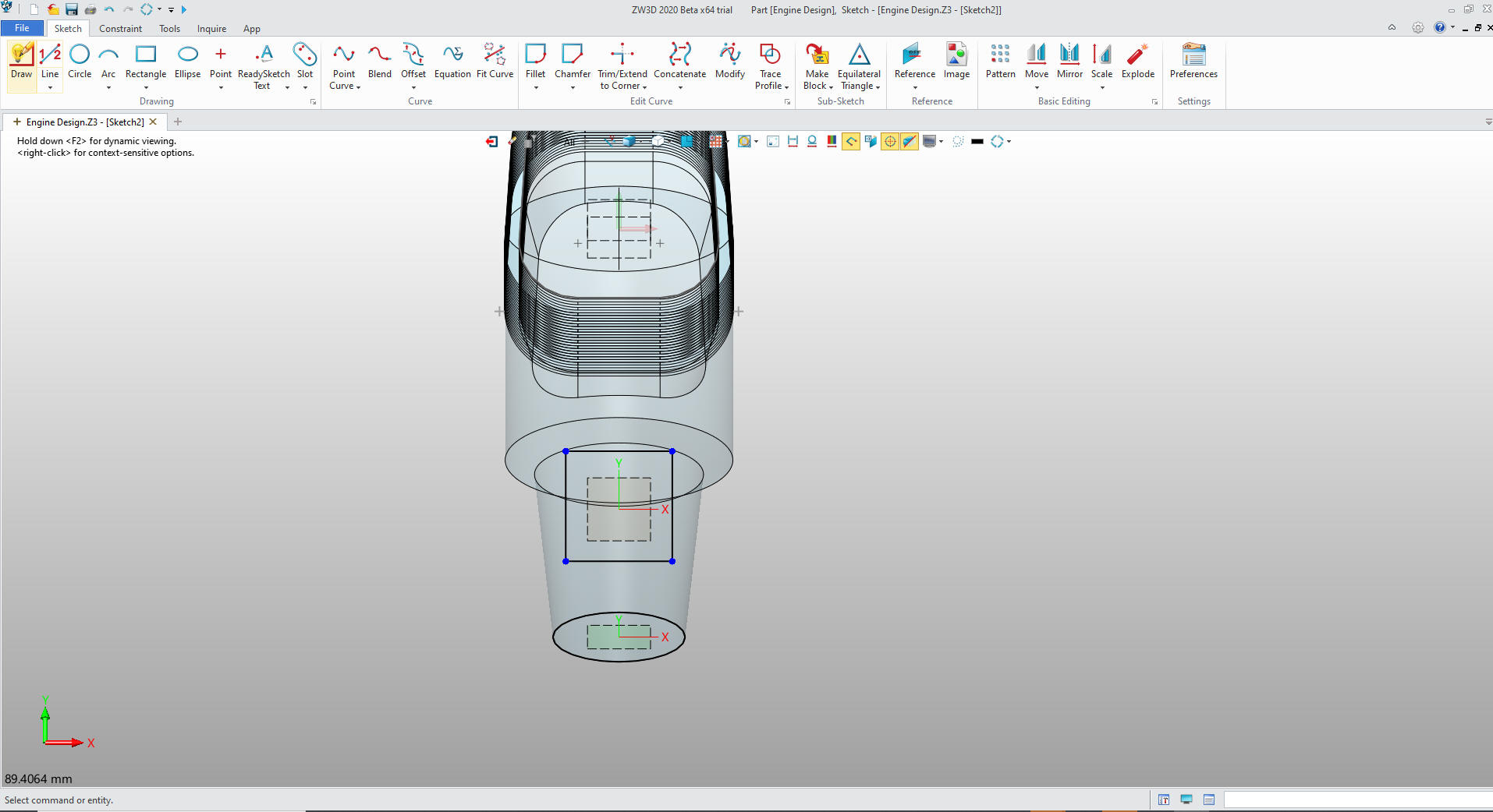
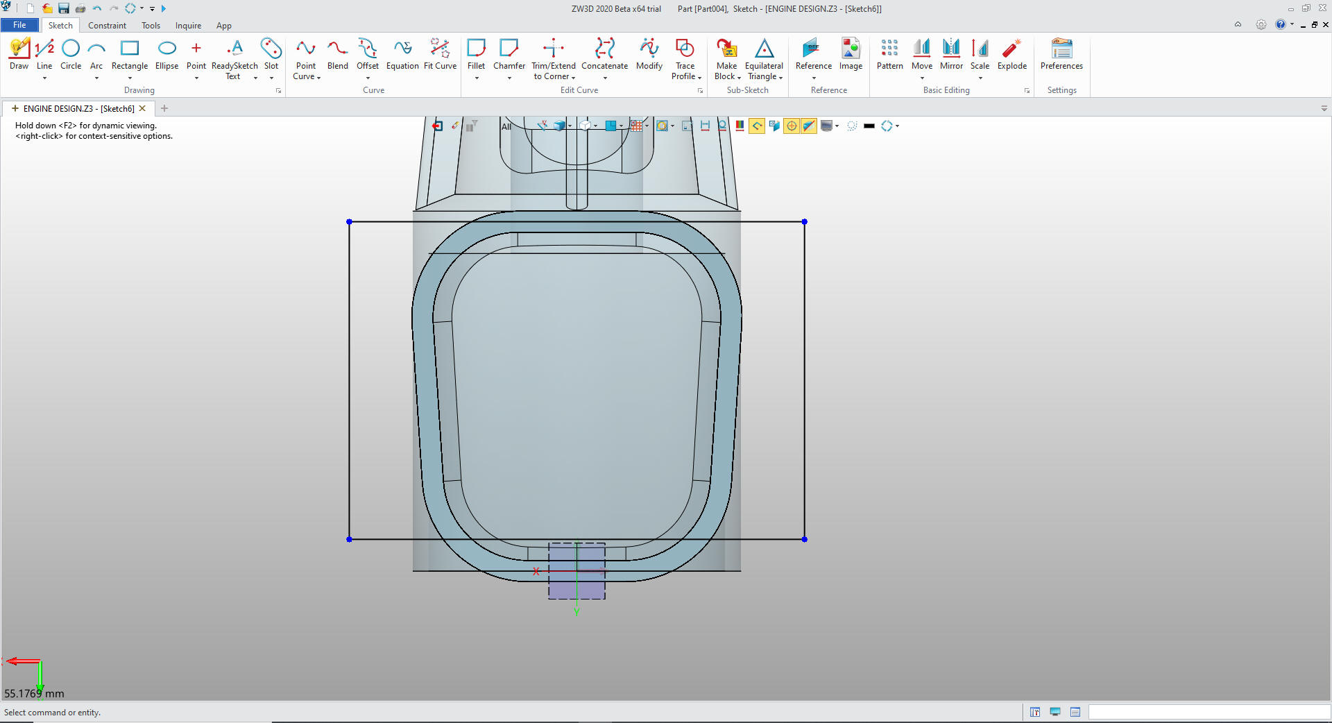
create the sketch of the outer shape.
We
now copy and edit the sketch for the main engine block by offsetting
the graphics by 2mm.
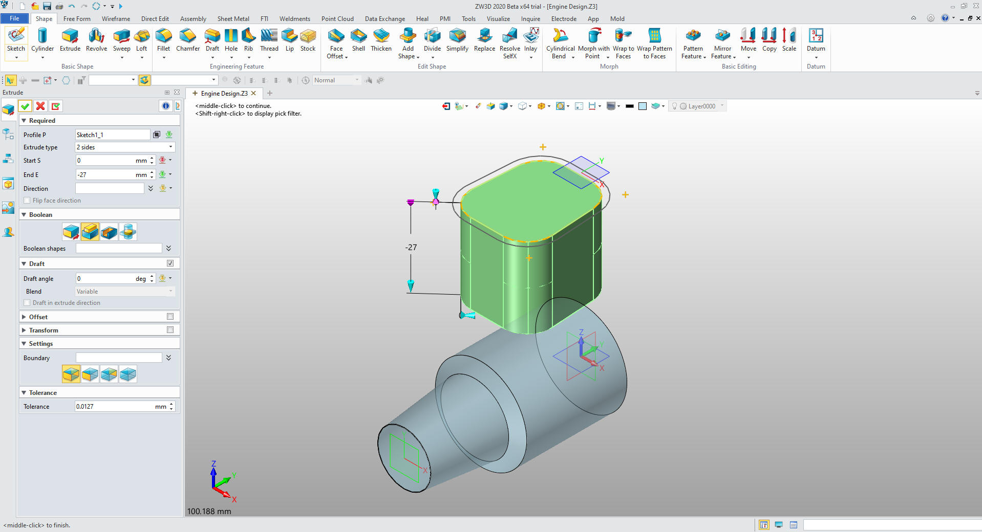
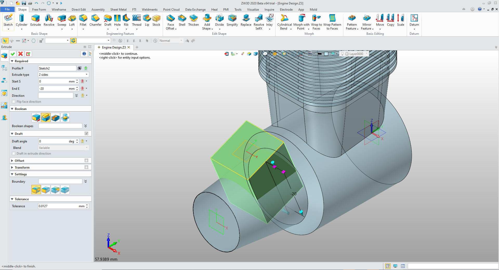
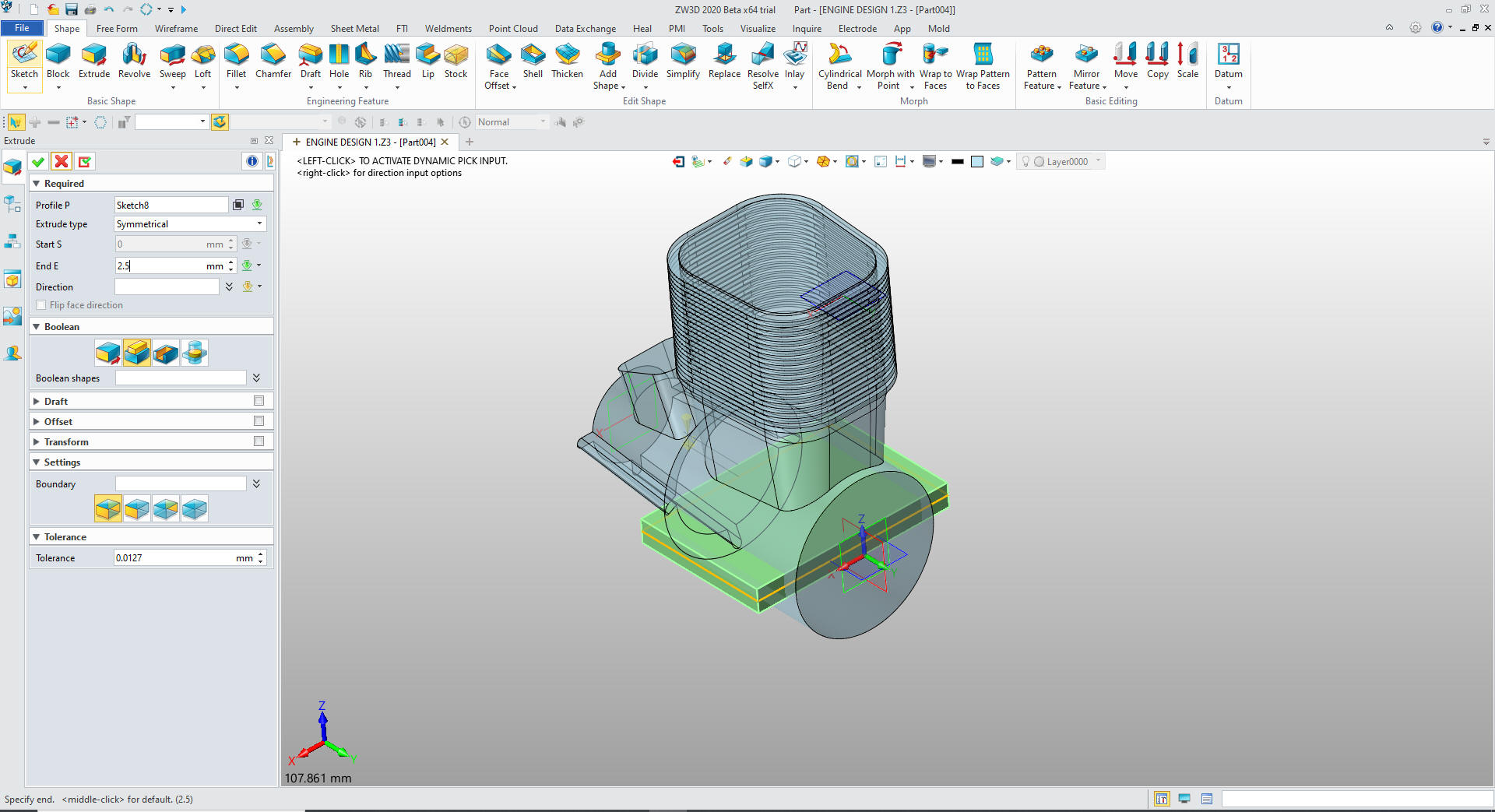
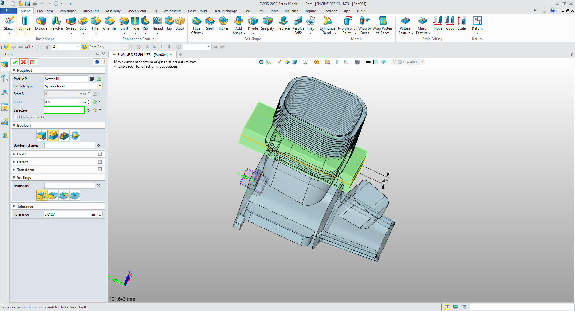
We extrude the inside sketch to the correct height and set to
add
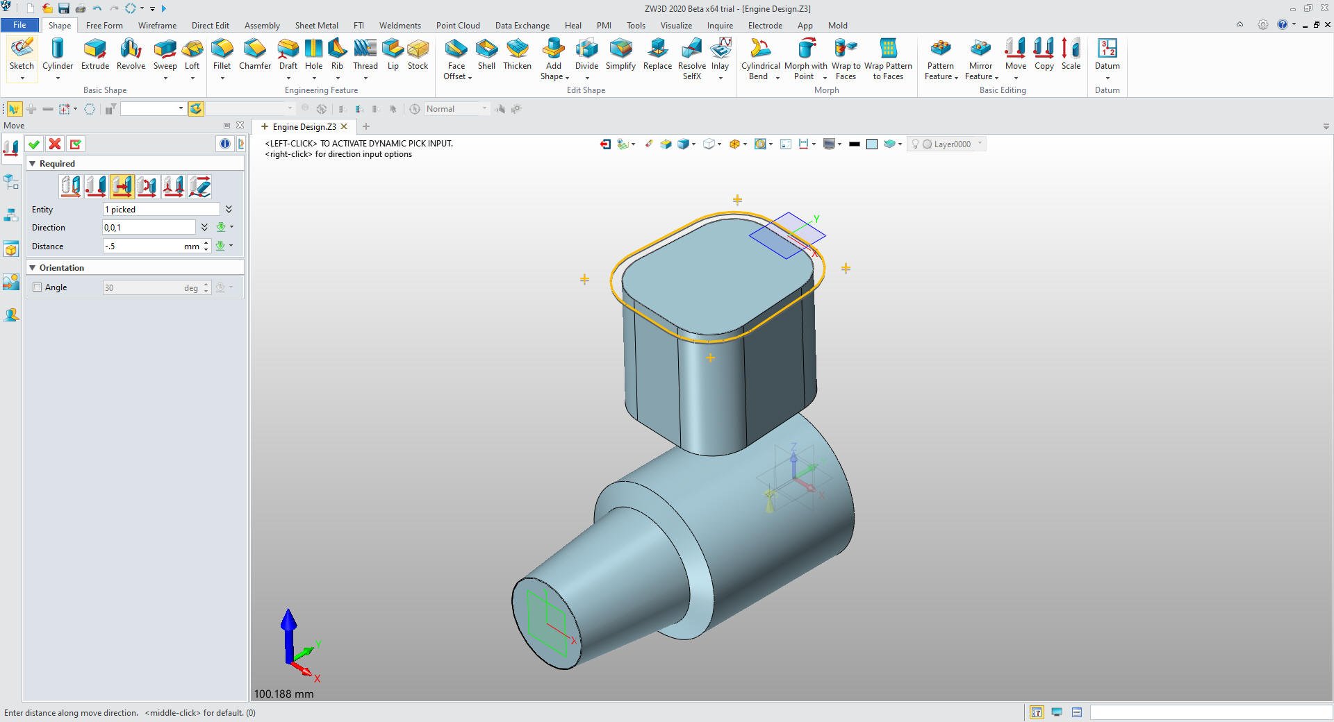
We
move the outer sketch .5mm
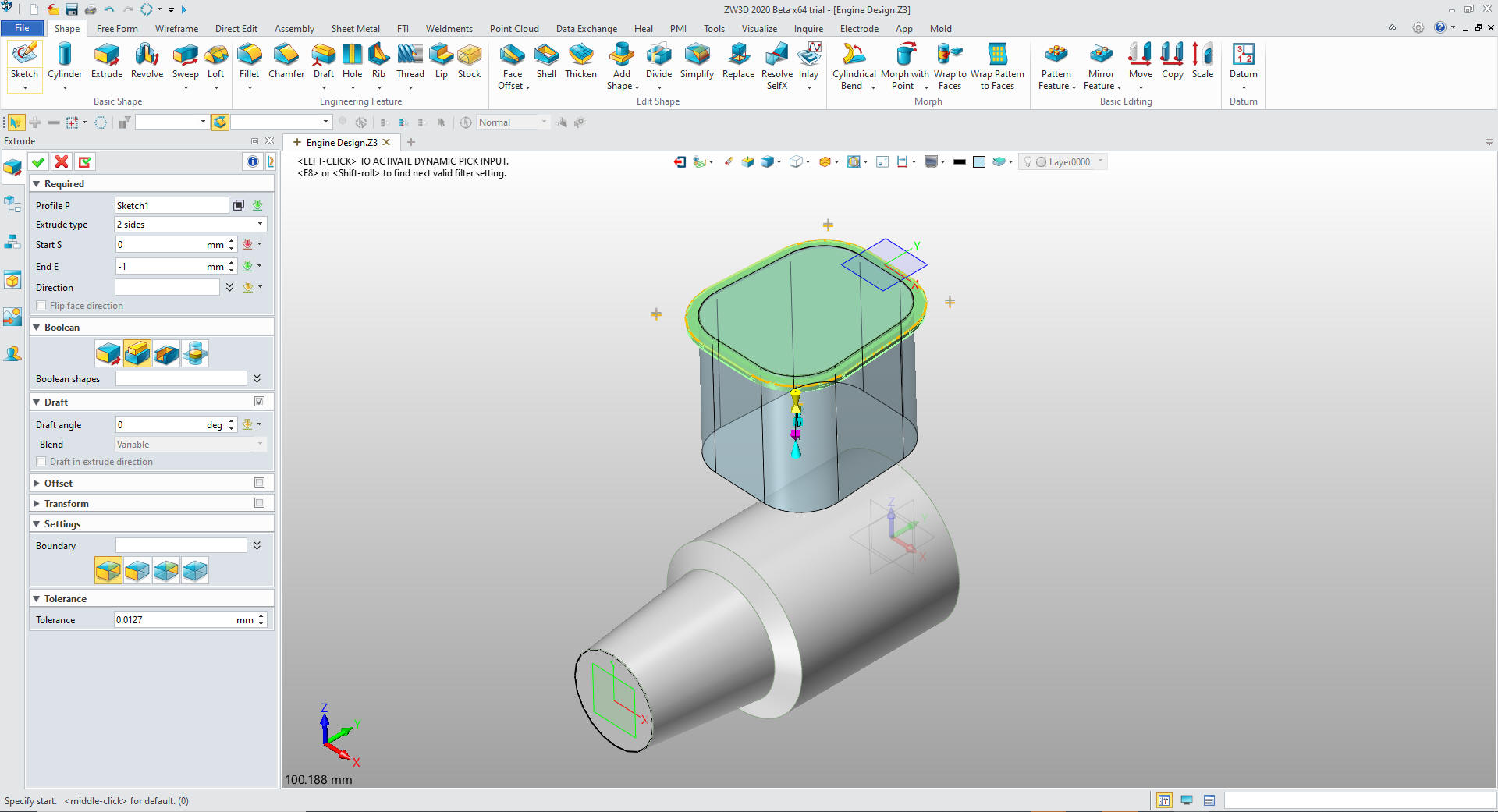
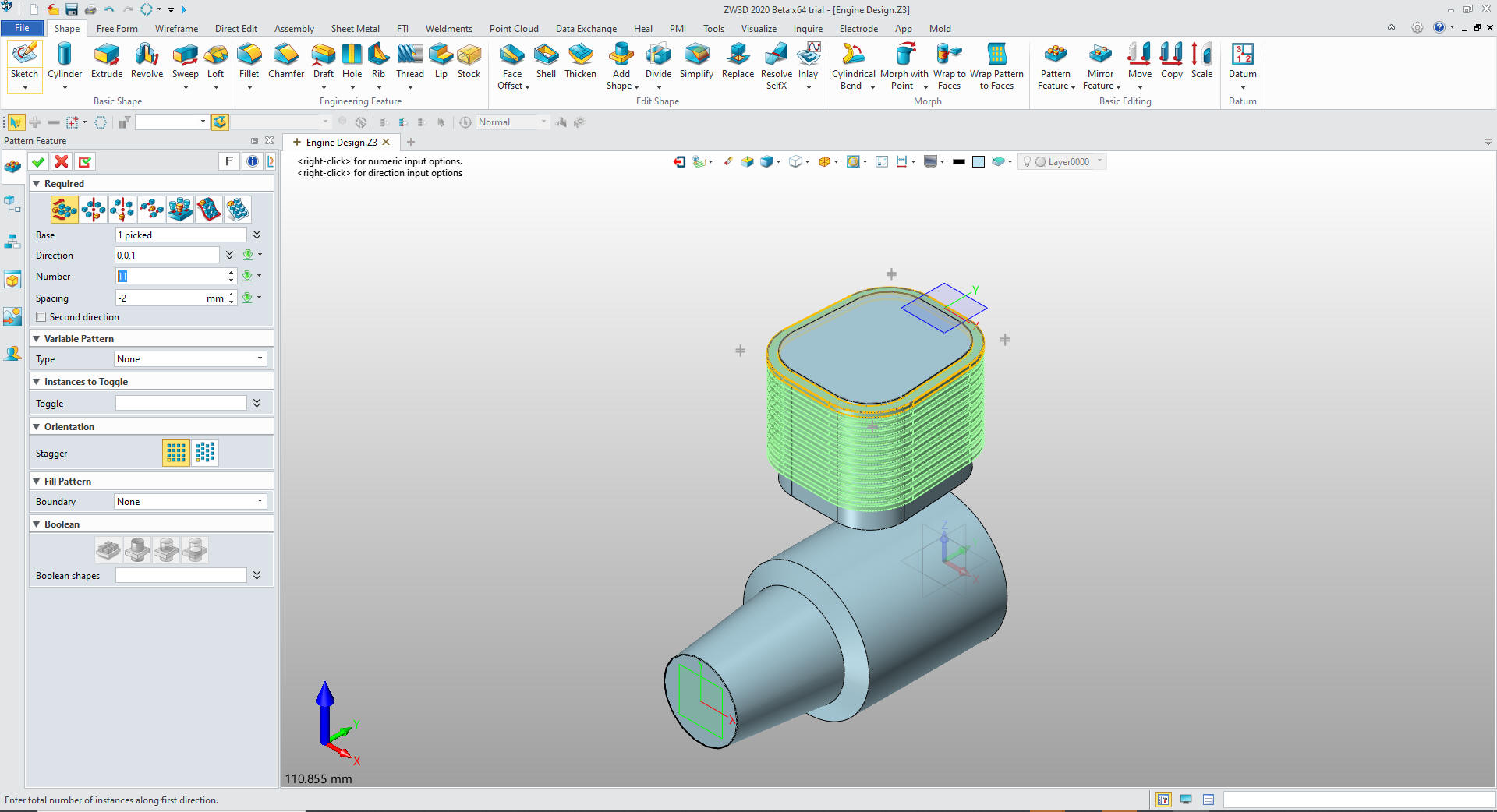
We extrude the outer sketch 1mm
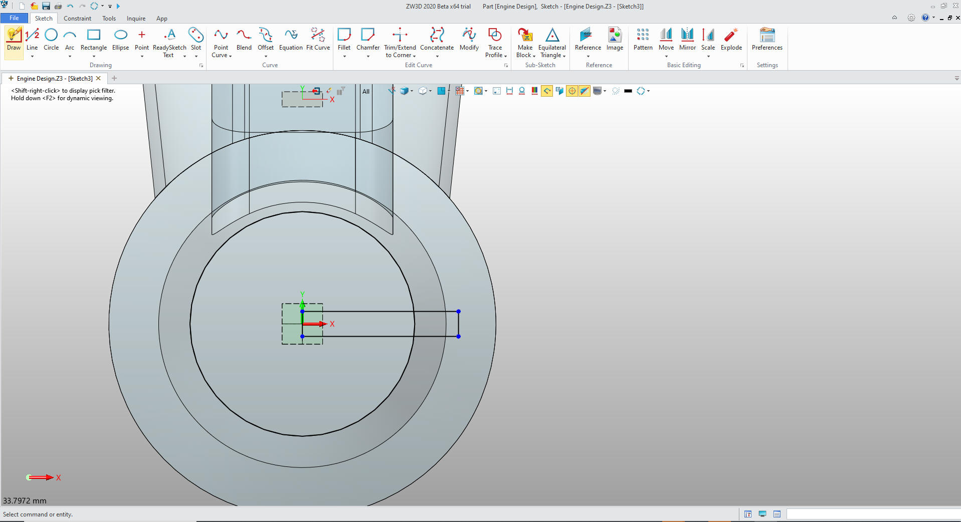
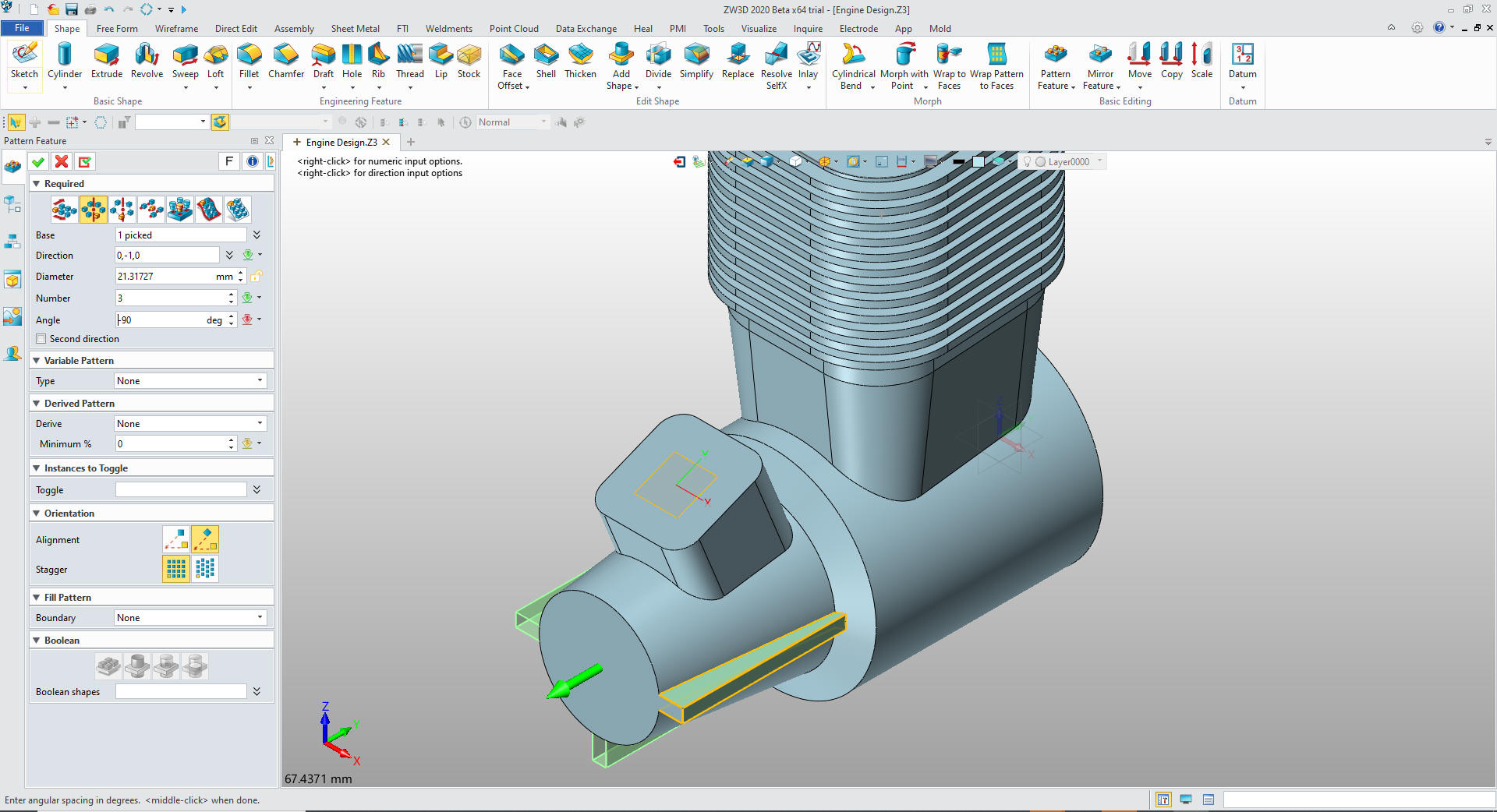
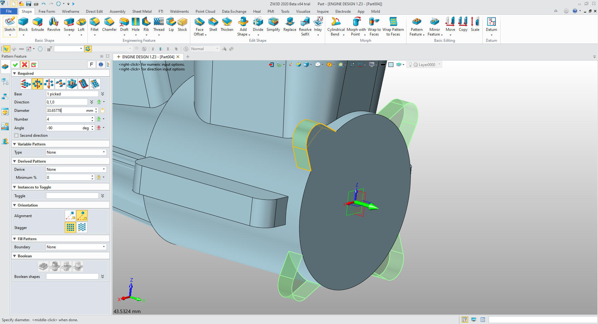
We pattern the new extrusion for 12 copies.
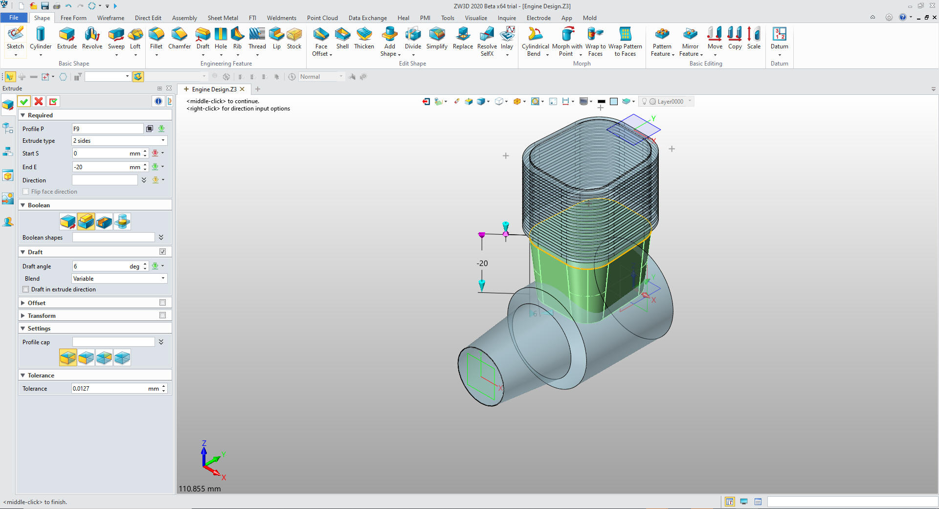
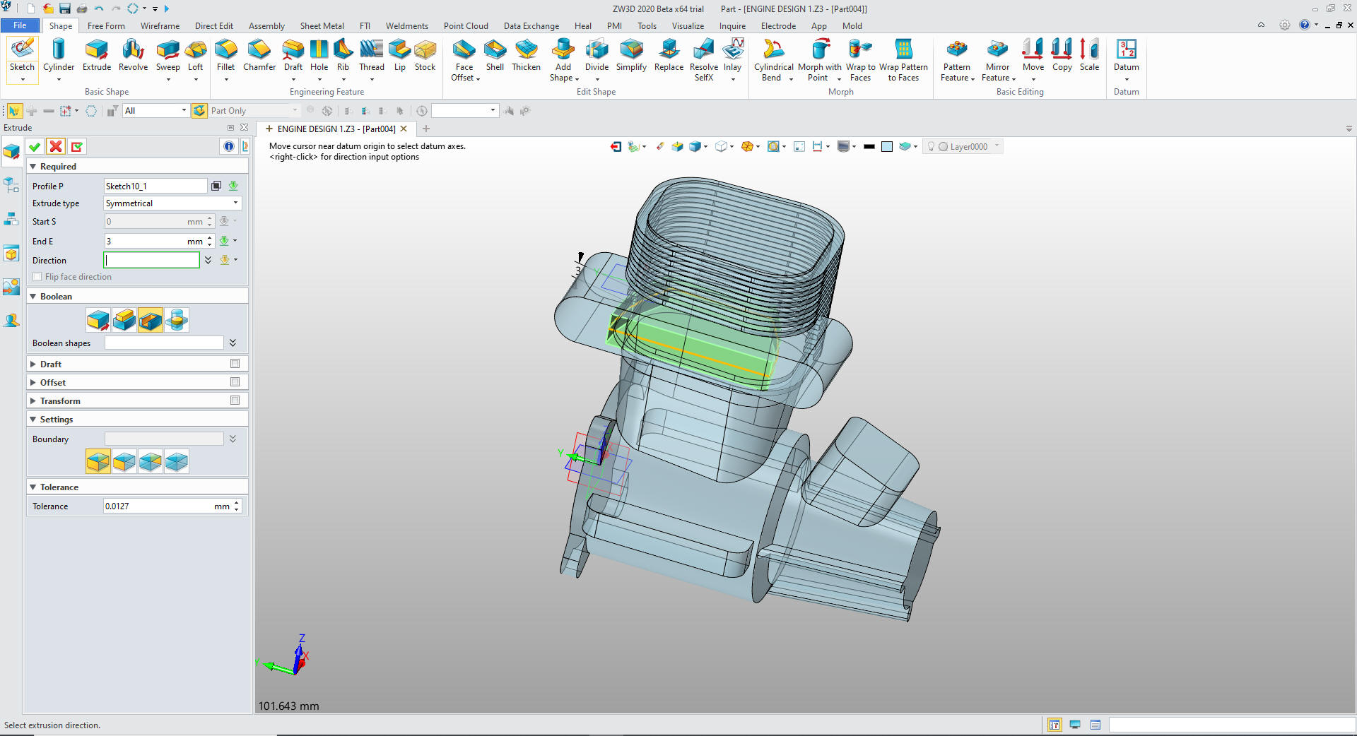
We
now just extrude the bottom 20mm with a 6 degree draft and set to
add
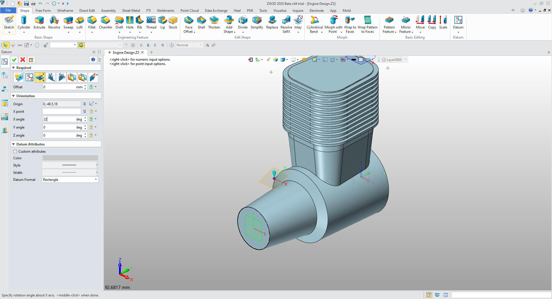
We
will create the front block by setting a plane.
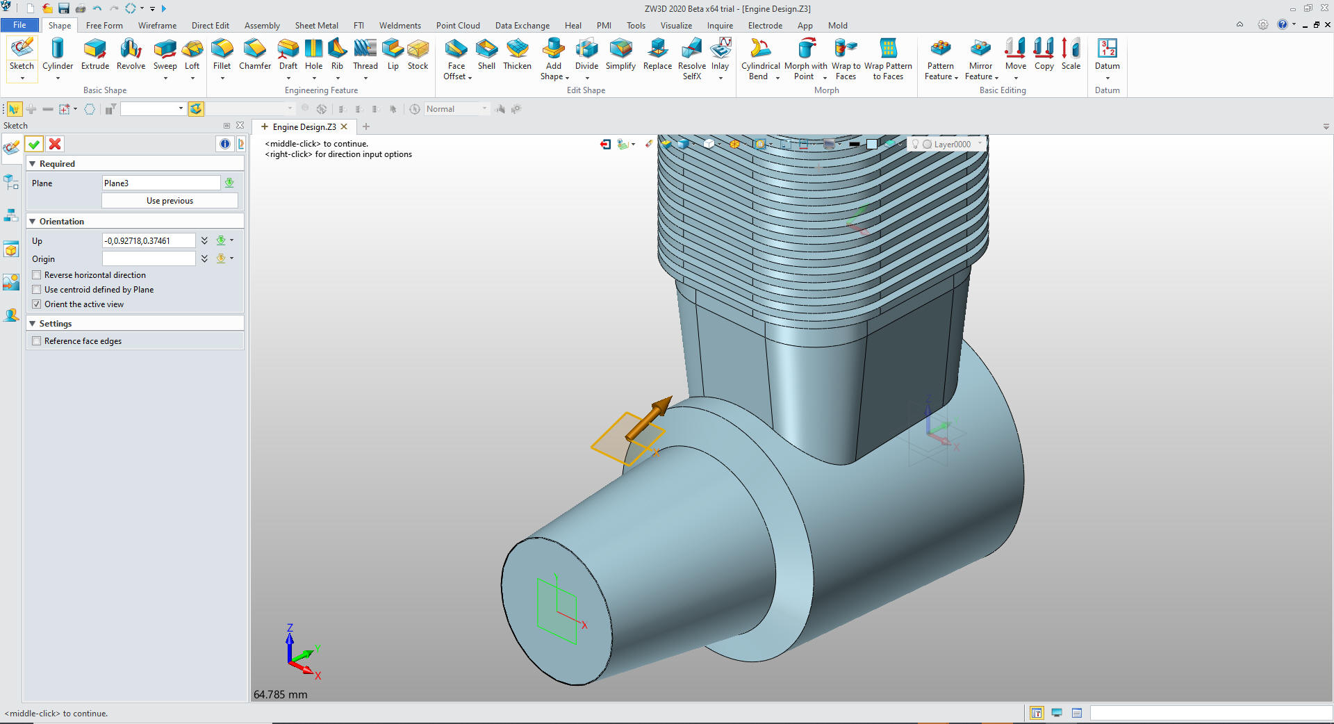
We
create a sketch on the plane.
We sketch the block.
We
extrude the sketch
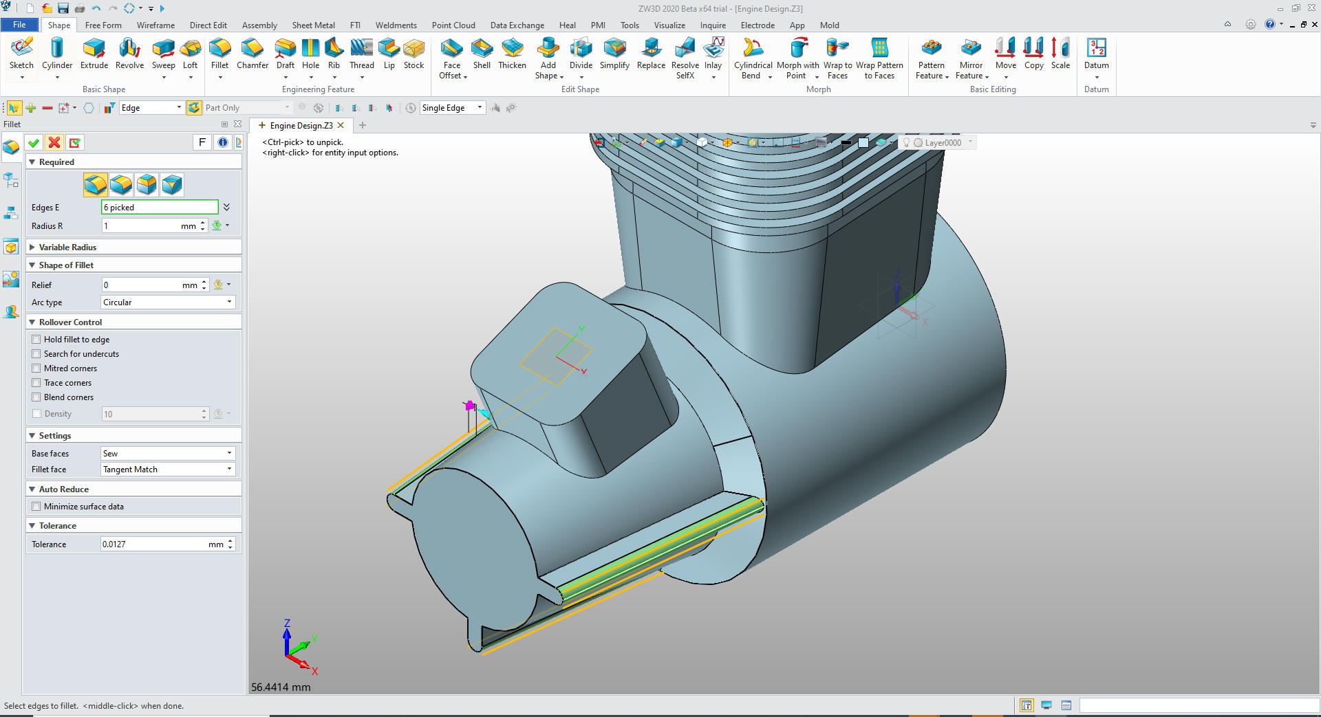
We put the fillets and we are
done with the block and we will create the ribs.
We will
sketch the rectangle on the front face.
We
will extrude and pattern the rib.
We
create the draft.
We
add the fillet on the edges of the ribs
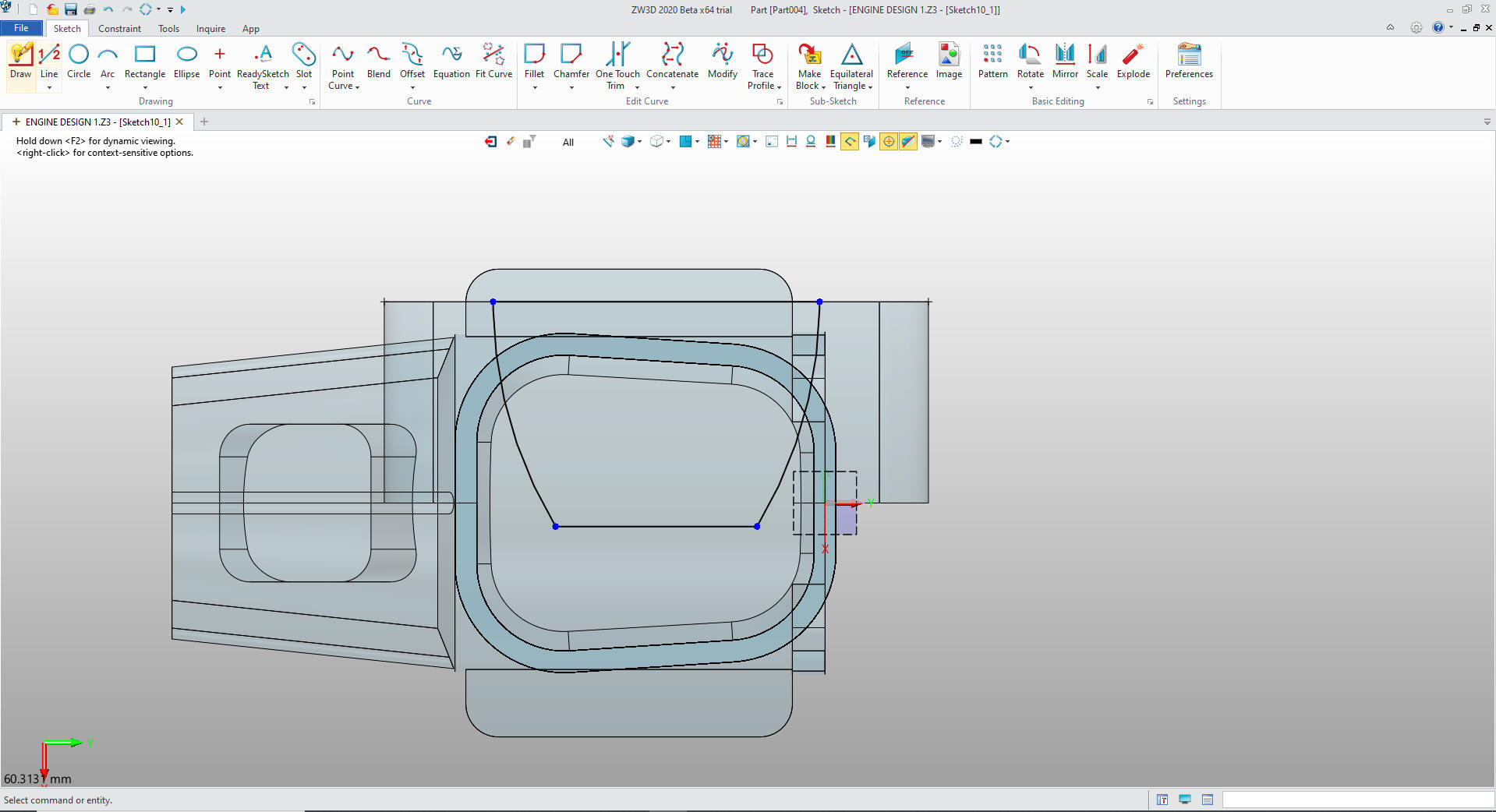
We now create the supports but creating a sketch on XY plane. And
create the profile. Notice that there are no constraints!
We exit the sketch and extrude the profile and set to add
We will put the fillets on the ends and set the sketch for the
flanges. I sketched the flange vertical and rotated it into place.
Exit the sketch and extrude the profile.
We use the pattern feature to create the other 3 flanges.
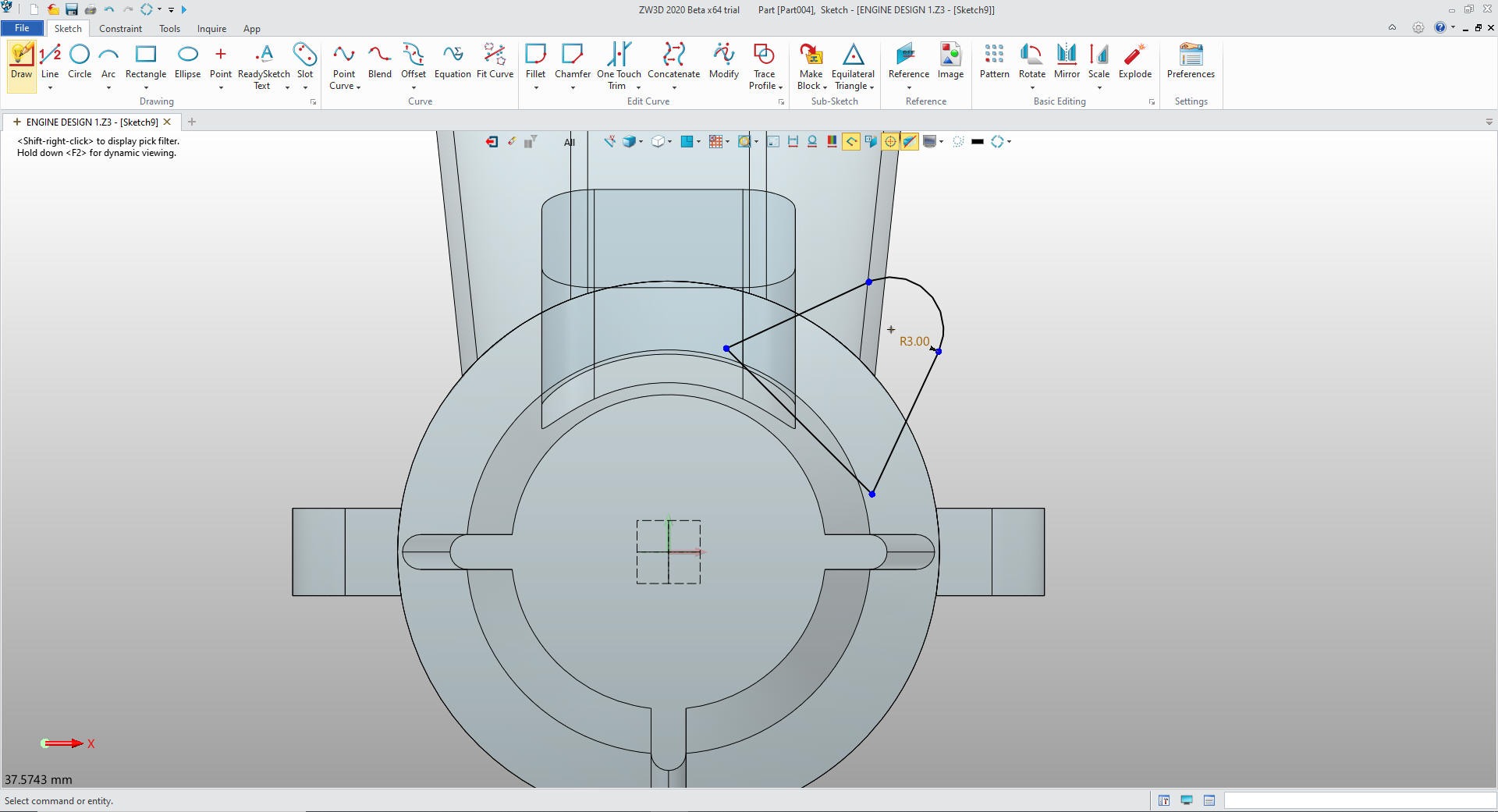
Now for the exhaust port.
We create a plane and locate it, we
create the sketch. Again I use no constraints.
We
extrude it and set it to add.
We
add the fillets to the exhaust port. We copy the previous sketch and
edit it since it is already located.
We extrude the profile and set to remove.
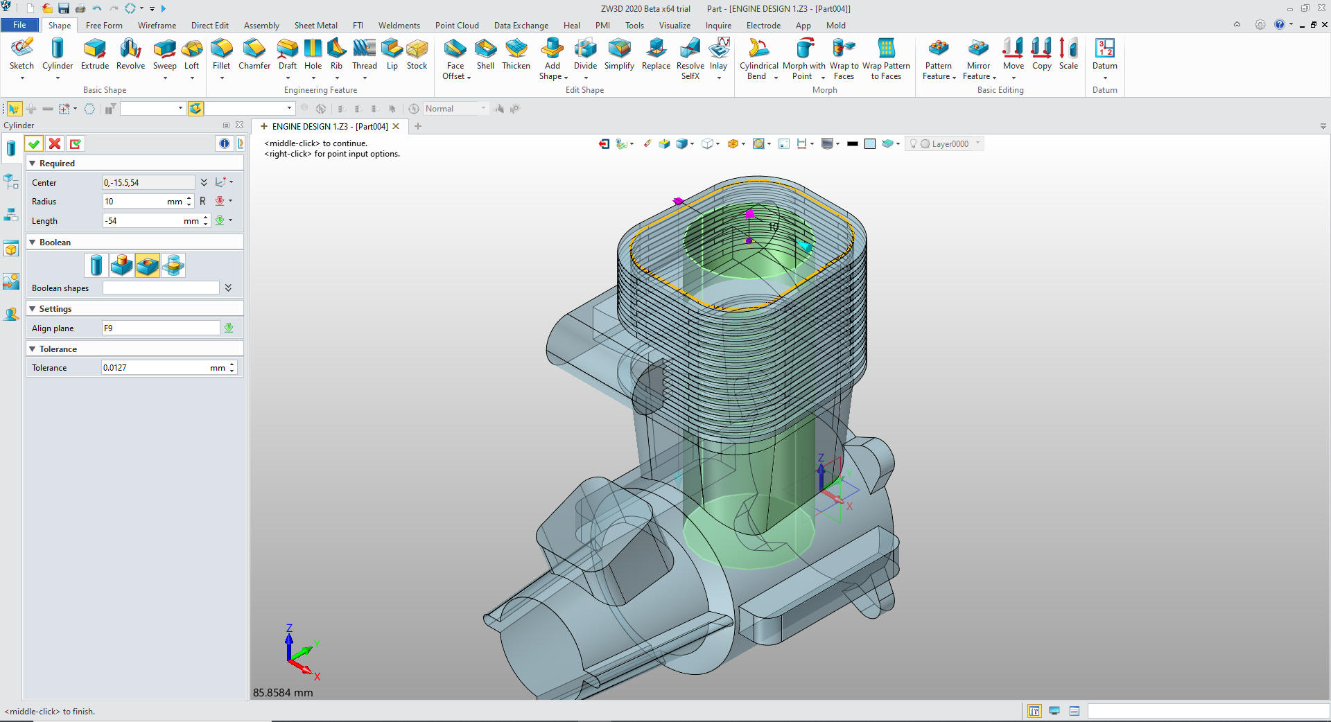
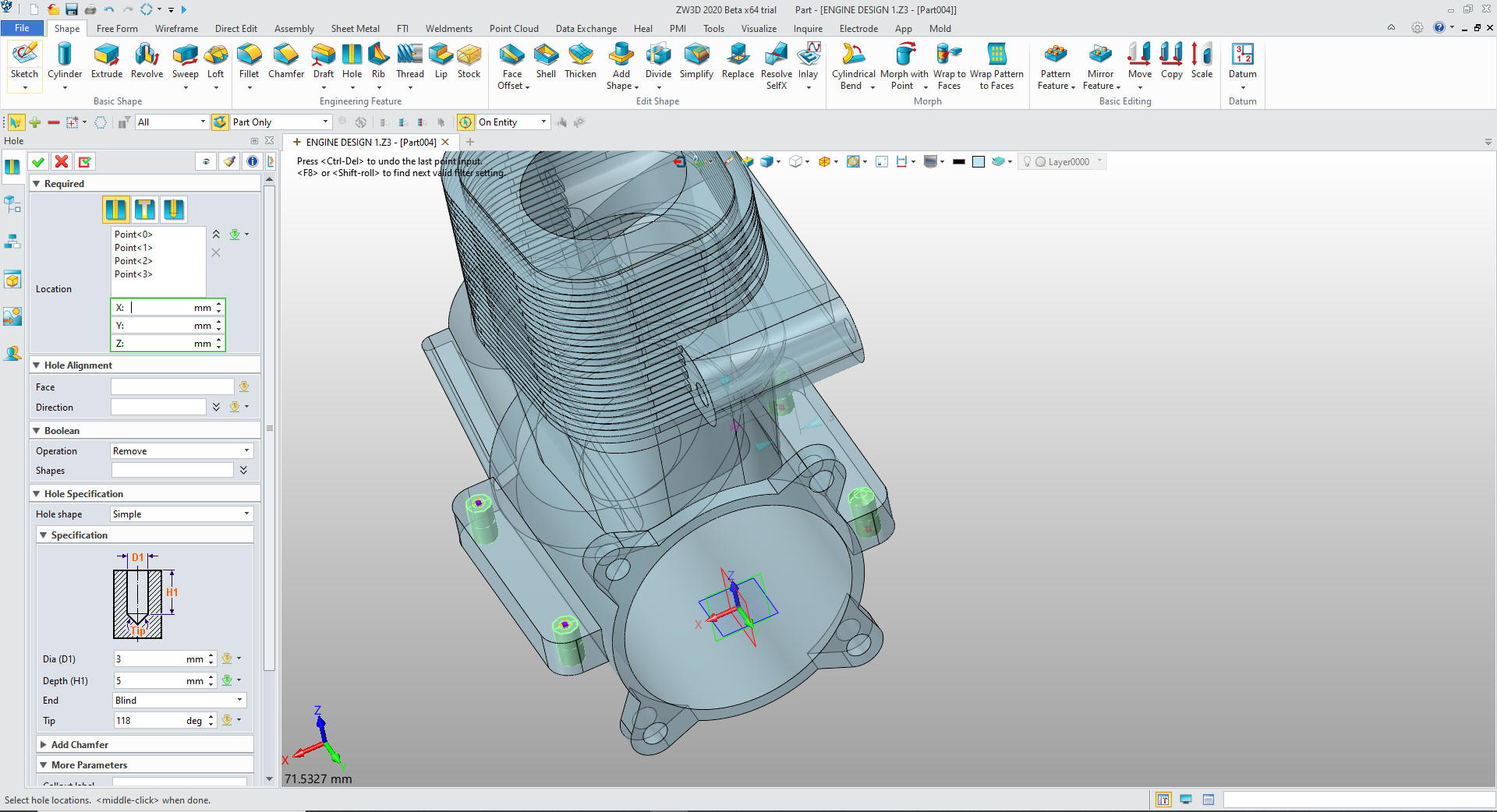
Now
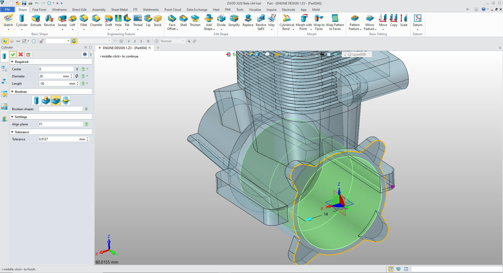
for the major holes. We use the primitive cylinder to create them
First hole the piston cylinder
The main hole
The
front hole
The boss hole.
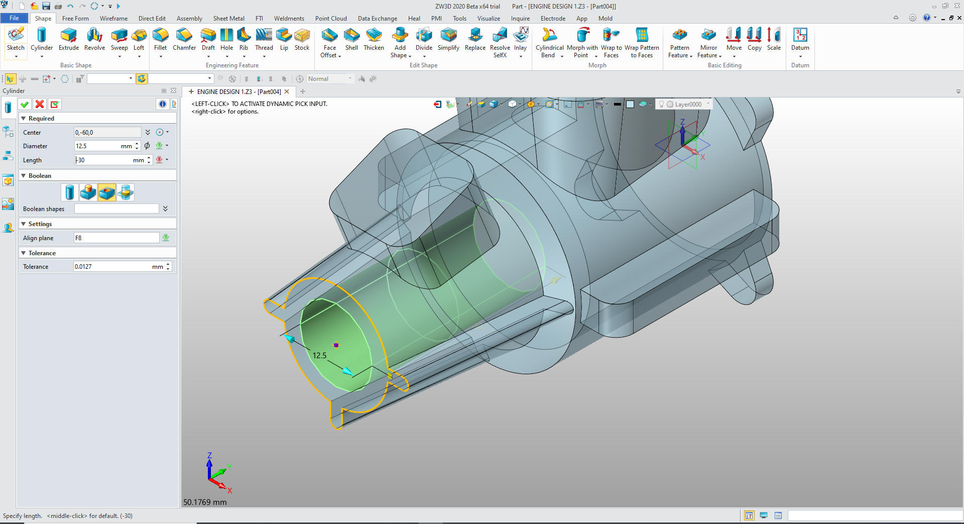
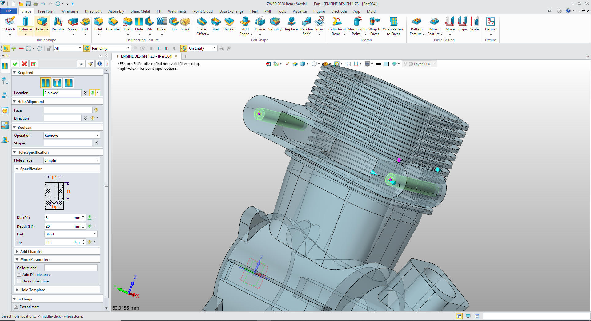
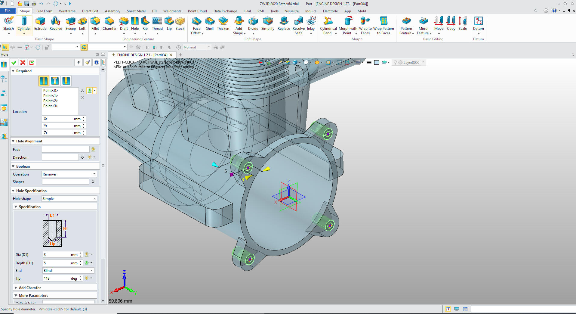
We will now put in the 3mm holes.
The holes in the aft flange
The holes in the support flange
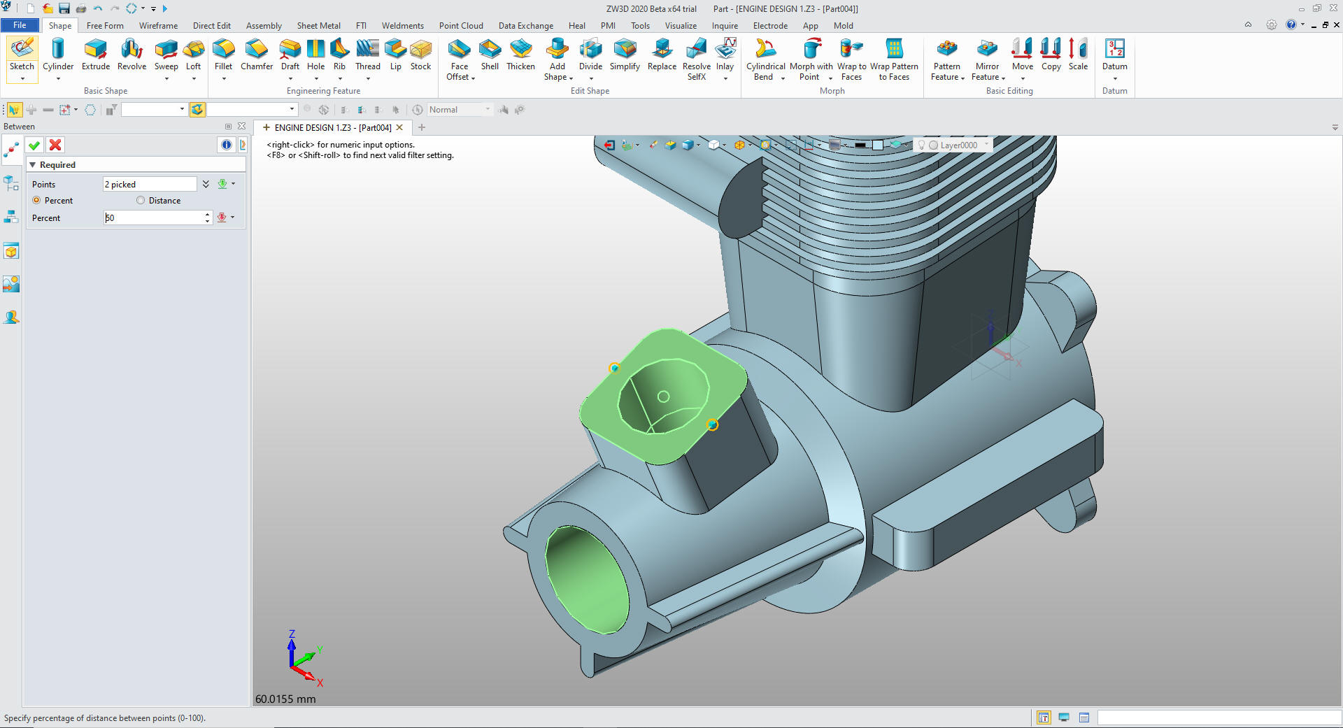
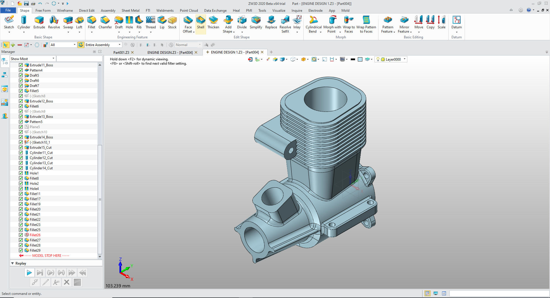
We now put in the fillets
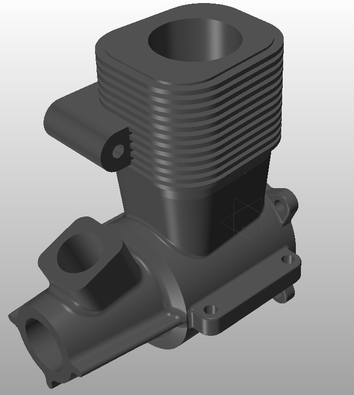
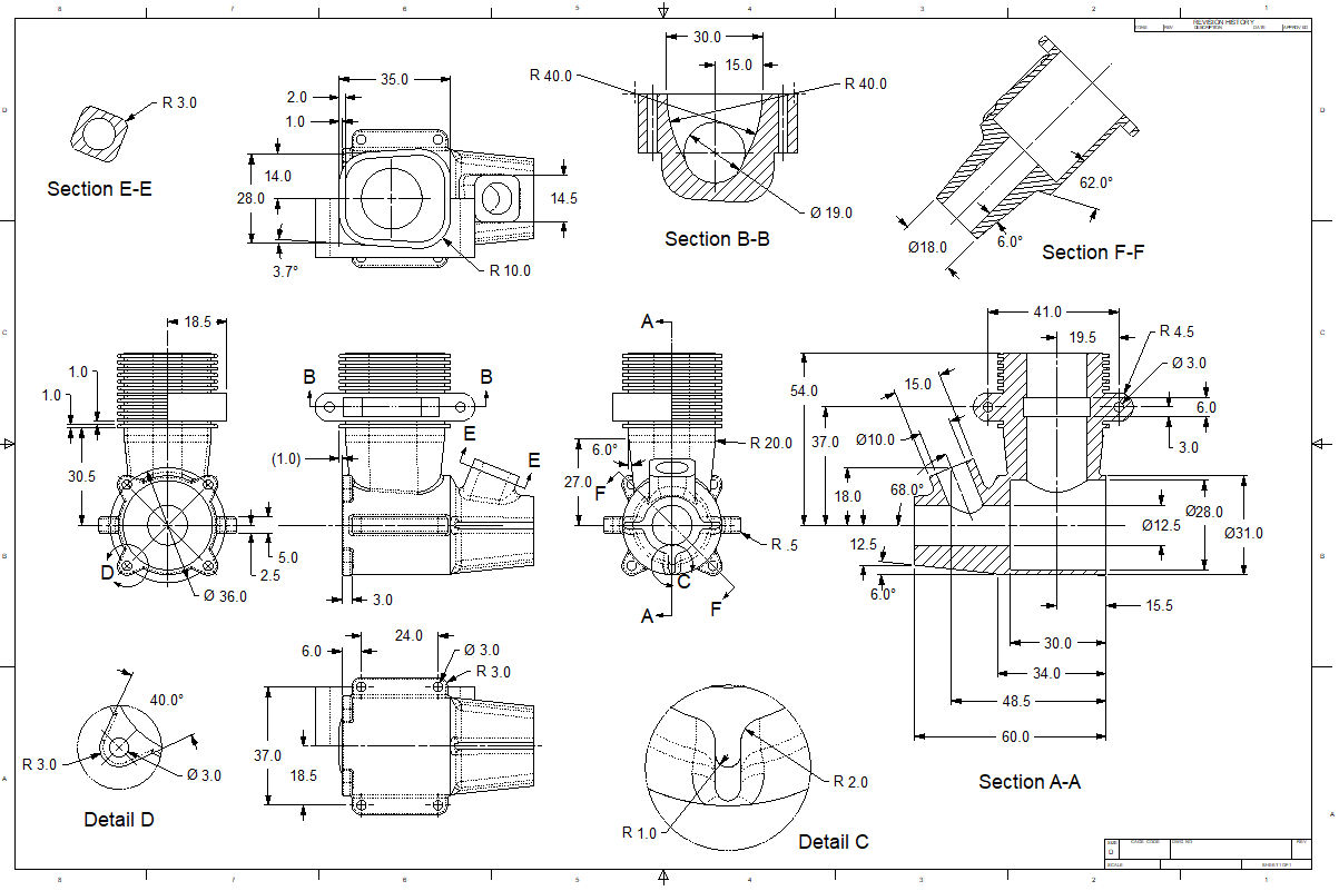
Here is a more correct AID (drawing).
You can see the two process that ZW3D offers are both hugely
more productive than the tedious constrained based sketching. You
can see more on modeling techniques here.
Give me a call if you have any
questions. I can set up a skype or go to meeting to show this part
or answer any of your questions on the operation of ZW3D. It
truly is the Ultimate CAD/CAM System.
If you are interested in adding professional
hybrid modeling capabilities or looking for a new solution to
increase your productivity, take some time to download a fully
functional 30 day evaluation and play with these packages. Feel free
to give me a call if you have any questions or would like an on-line
presentation.