3D Modeling Techniques
ZW3D vs Creo Lesson Two Streamlined Sketching/Feature Based Modeling A Bonus
Streamlined Sketching lesson!
I saw some Fusion 360 exercises online and
I decided to compare ZW3D. It quickly turned into a study in
modeling techniques. I have created fifteen "ZW3D
vs Fusion 360" six
"ZW3D
vs Solidworks" and
"ZW3D vs Creo" lessons to
show the difference between ZW3D and the two programs and my
modeling techniques. I found the Fusion 360, Solidworks and Creo
presenters wasting massive amounts of time with overly complex
constrained sketching procedures. I was so unimpressed that I
decided to model the parts or assemblies showing my modeling
techniques plus ZW3D's superb design system.
Many of these modeling techniques can easily
be implemented even within the most Solidworkish of systems. I call it
Streamlined Sketching and Feature Based Modeling. Please review a few of the above IronCAD vs Fusion 360, Solidworks
and Creo
lessons, there are some very stark differences.
Please watch
a Creo user model this part!
With all the
tedious constrained
sketching for this simple part for the Absolute Beginner, you can imagine a
complex part?
Here is
the drawing if you would like to give it a try. This is not a 3D
drawing it is a detailed Isometric. There is no such thing as a 3D
drawing. A drawing it a document done on a 2D plane.
While creating 3D models from drawings is the very best
way to learn 3D CAD and maybe some design techniques it does not
expose the designer to the design flexibility necessary in design. IronCAD is all top down due to the single model environment.
Creating mating parts is a cruise. But modeling is just one aspect of a
well designed productive 3D CAD system.
Creo
is a marginal 3D CAD system based on the dated Pro/e history
based modeling system released in 1988. I sold Pro/e years ago
and found it not productive enough
for our engineering department. We use what we sell. That gives us
the experience to effectively support our user base.
I would do a
video, but I really am not good at it. So I will show you step by
step. I will try and get ZW3D support to create one. They are
very good.
The modeling technique is hugely responsible for
the level of productivity. Those of you that are only trained in the
sketch, sketch, constrain, constrain world are truly limited by not
using the freedom of feature based design, that is available in even
the most Solidworks-ish of CAD systems. If your
designers are designing in these very unproductive and time
consuming processes it might be time to review your standard design
processes. Don't have any do you?
These lessons have actually turned into exercises in
modeling techniques as compared to showing a more productive CAD
systems. Again, I say, there are many different ways to model a part.
I see with my exposure to direct edit modelers like CADKEY, I
rarely sketch like you see the Solidworks fellow doing. I have always
created my basic sketches by mostly creating offsets and extending
and trimming or. It seems to be much easier. I never put in a fillet that
can be created later. What do you think?
Since ZW3D
is a sketch based product with a primitive shape option I will
create the model in both processes. The sketched based model will be
done with StreamLined Sketching to show the incredible simplicity
and productivity over the de facto constrained sketching.
We are already in
millimeters. So we can start modeling.
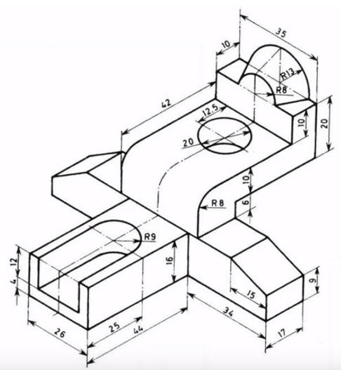
Modeling with Primitive Shapes
Again
I instantly differ from the Creo presenter by inserting a
primitive block at X0Y0Z0 and sizing it. We have a variety of
options for creating the blocks, we will use center and height. This block makes up the base of the
part.
While he is concerned about sketching, I am thinking of basic shapes of the part.
Note: Pro/e clones have been starting with the sketch for almost
30 years. Even today the sketch is the only option in most programs.
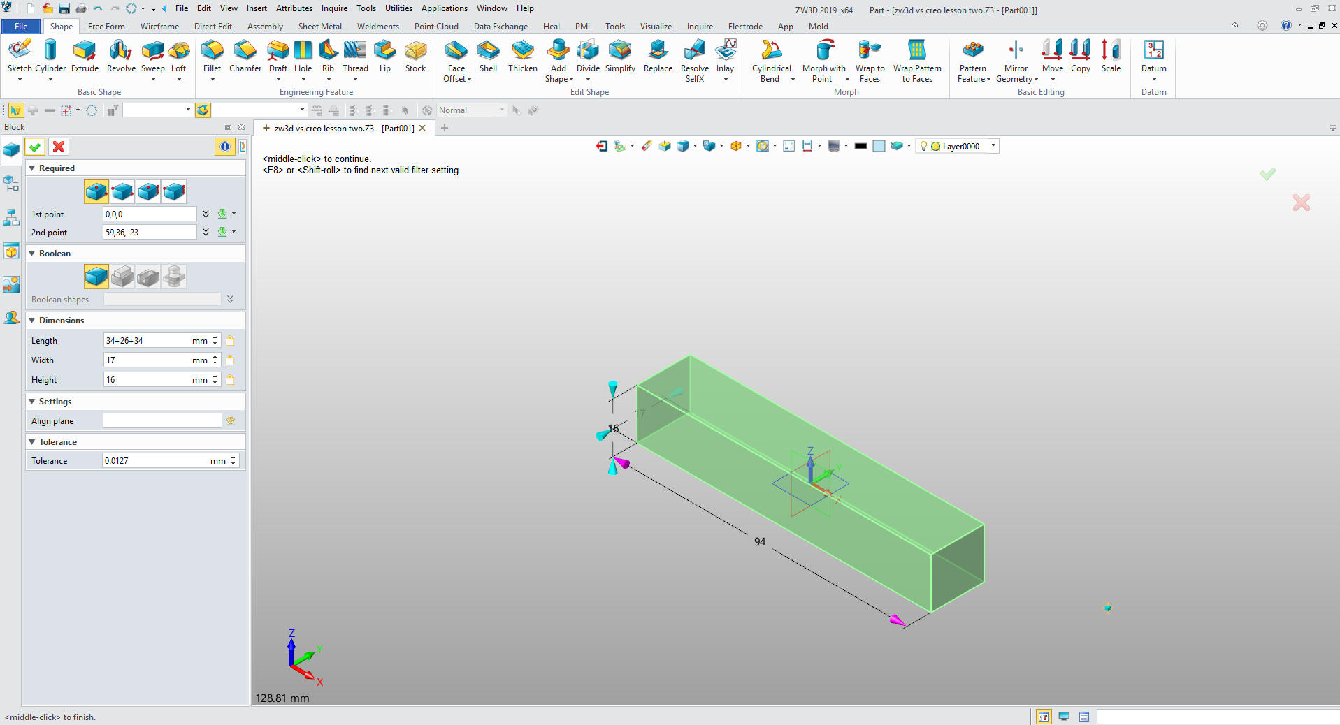
We insert a primitive block
using corner on the lower corner locate and size.
Note: It takes a bit of playing with the blocks to
get proficient. I have introduced many of our user to this function.
I believe using primitives effectively can increase your
productivity 30% if part of your design process.
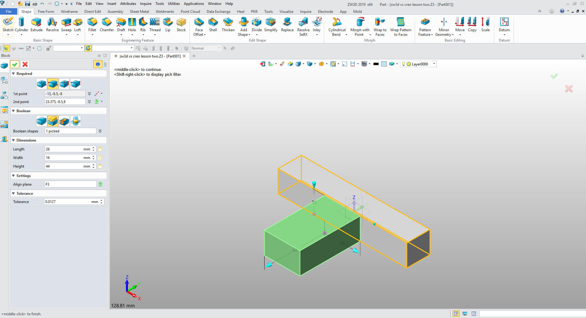
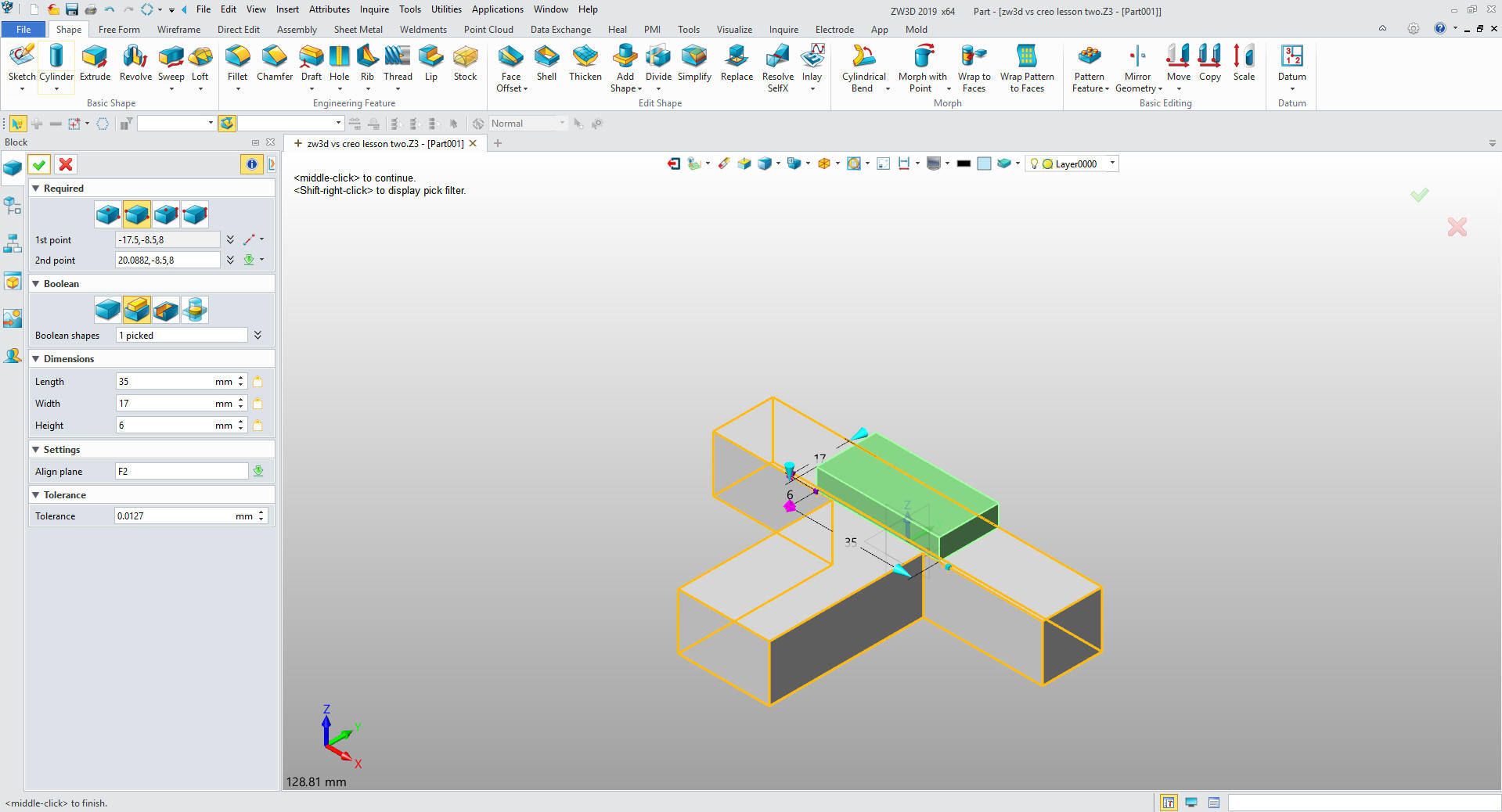
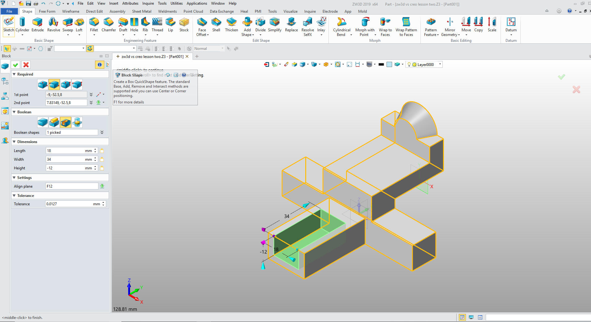
We insert the small primitive block
using corner on the lower corner locate and size.
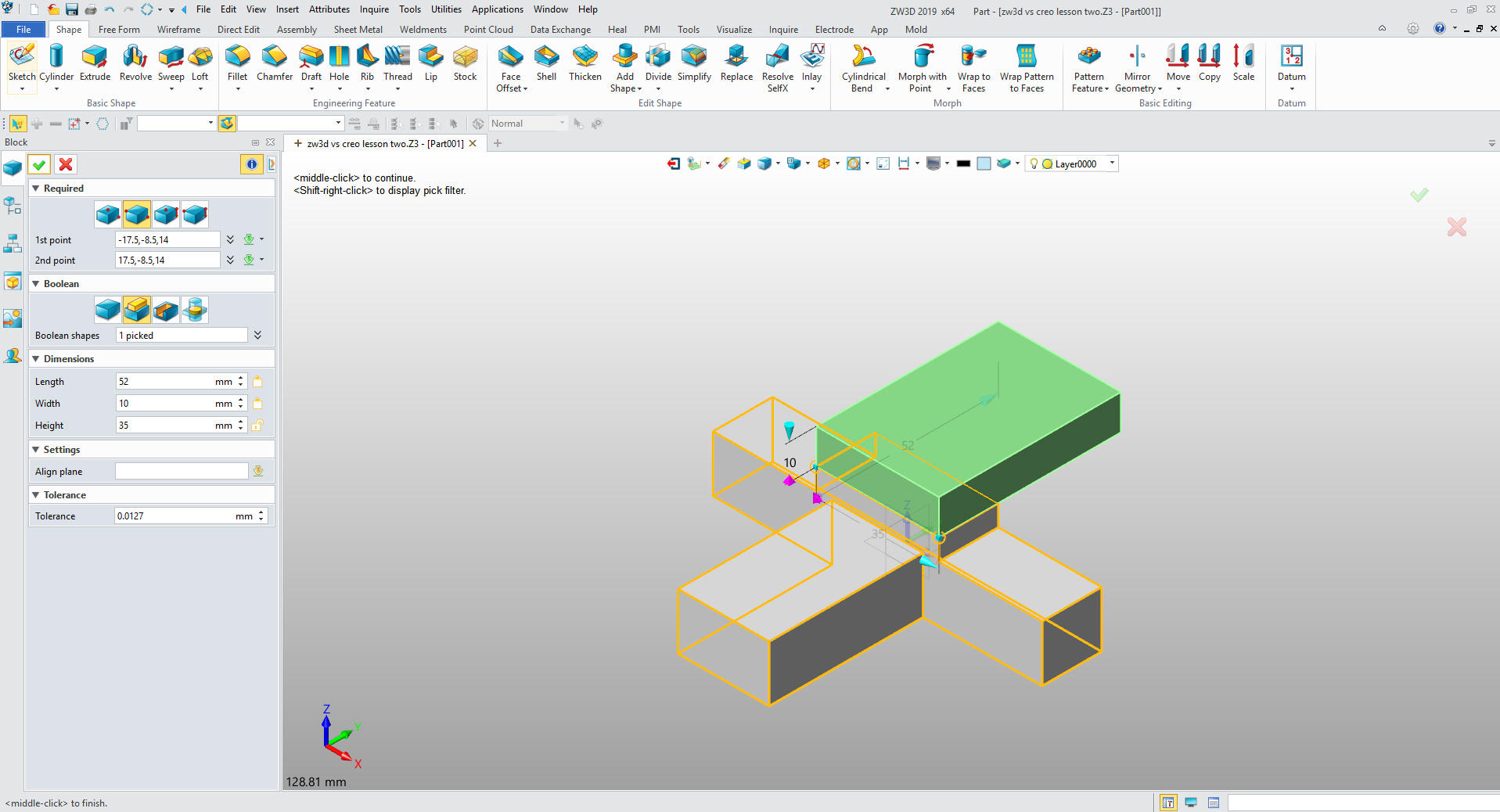
We insert
the top primitive block
using corner on the lower corner locate and size.
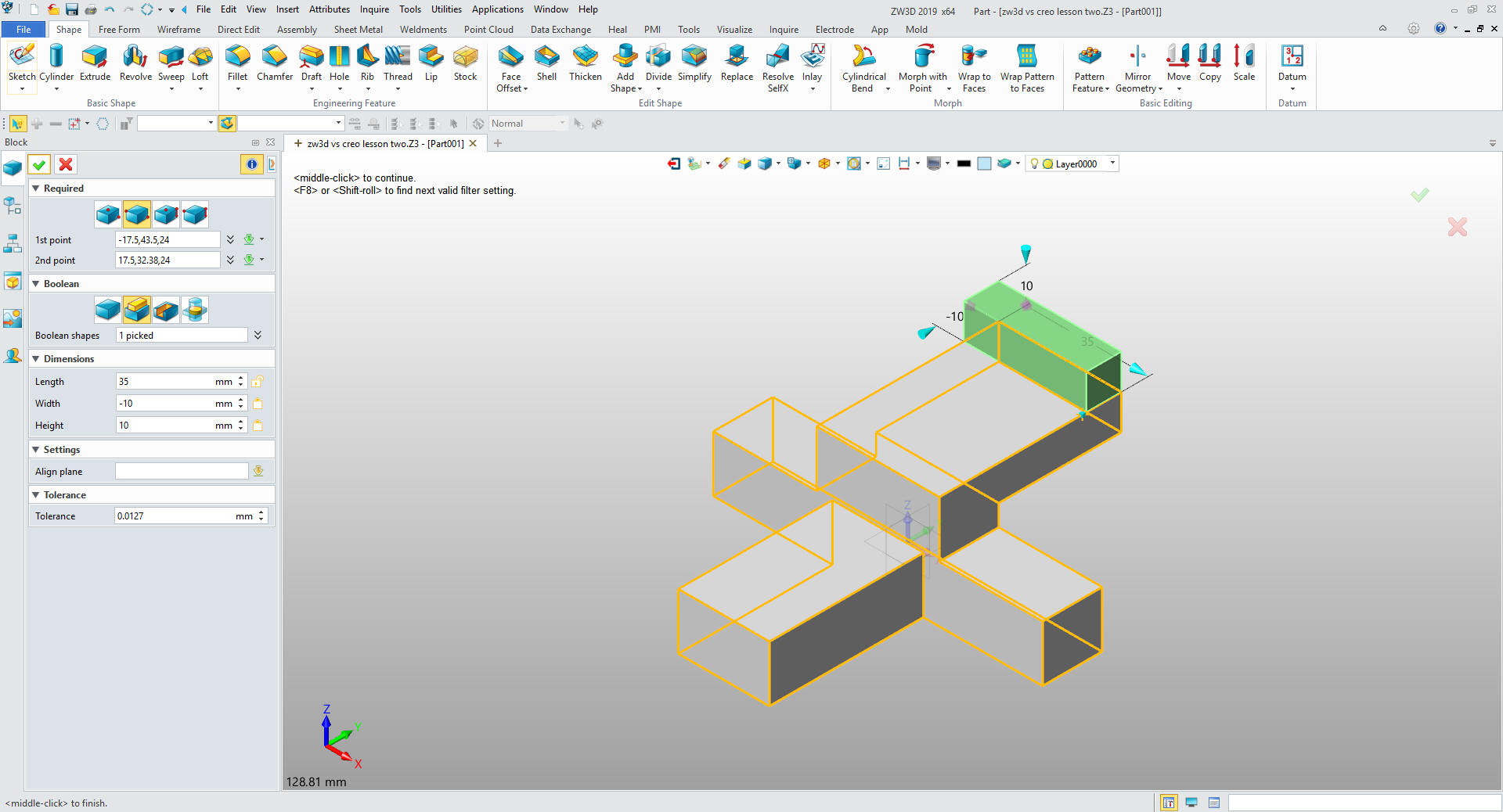
We insert
the last primitive block
again using corner on the lower corner locate and size.
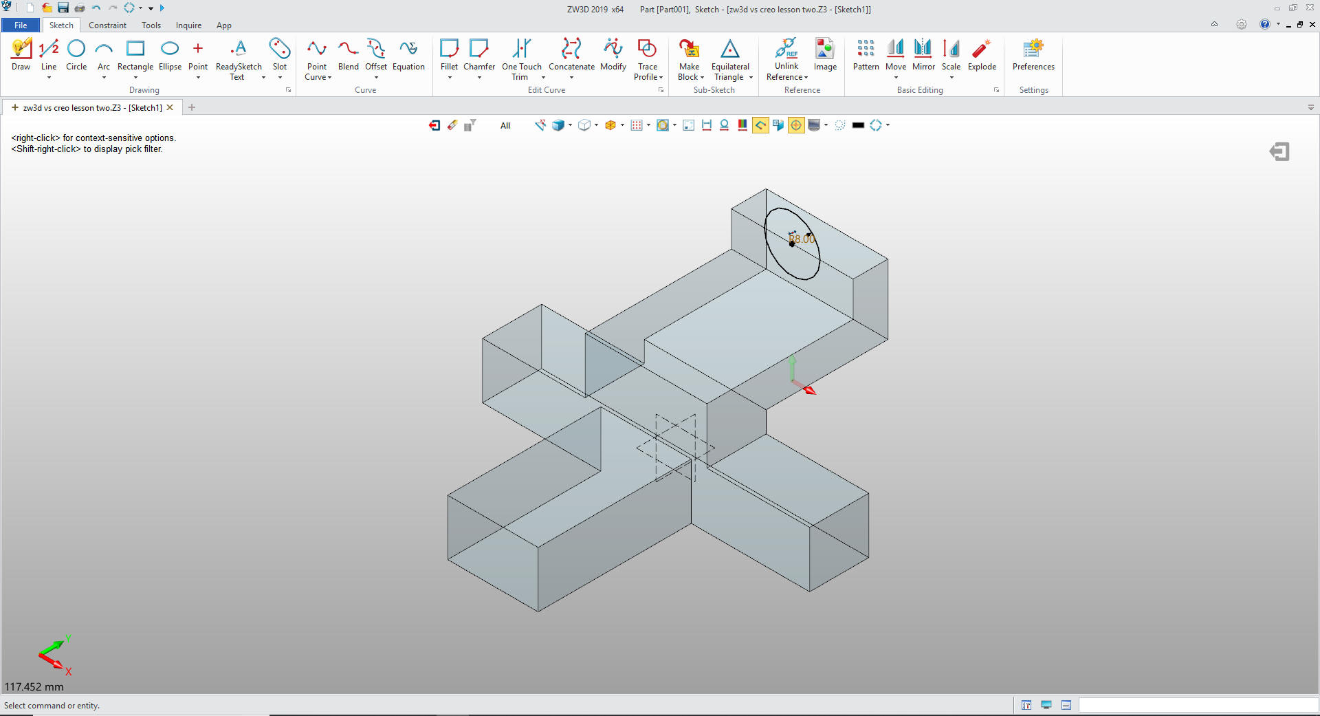
We
will no create the top feature with the love command. We will create
the sketch of the first circle.
For
the next sketch will create a plane in the orientation of the first
sketch and create the second circle that will make up the loft.
There is no need to take the extra steps to create the
semicircle arc since the feature is going to be added.
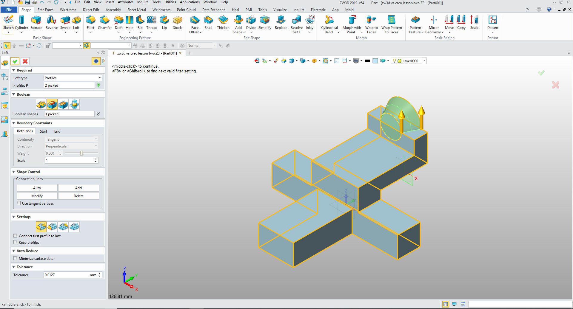
Now for the loft we just pick the two circles and use
Now for the
remove block. You can
instantly see the difference. We think in terms of shapes instead of
sketches. We just set the operations to remove instead of add.
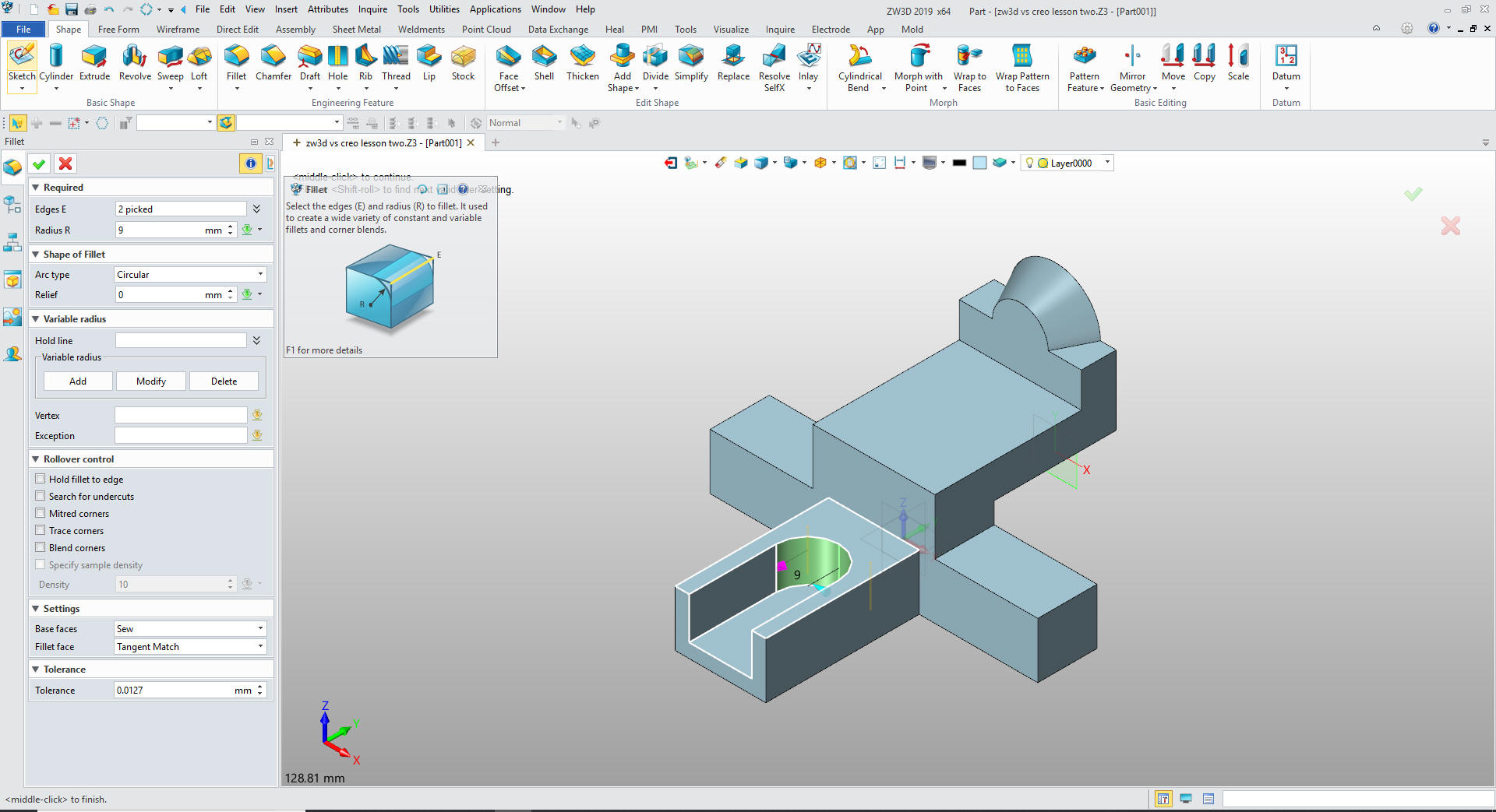
We
add the fillets for the cut. I believe we should use features like
fillets when ever we can. Much easier for modifying the part later.
Always remember the only constant in engineering is change!
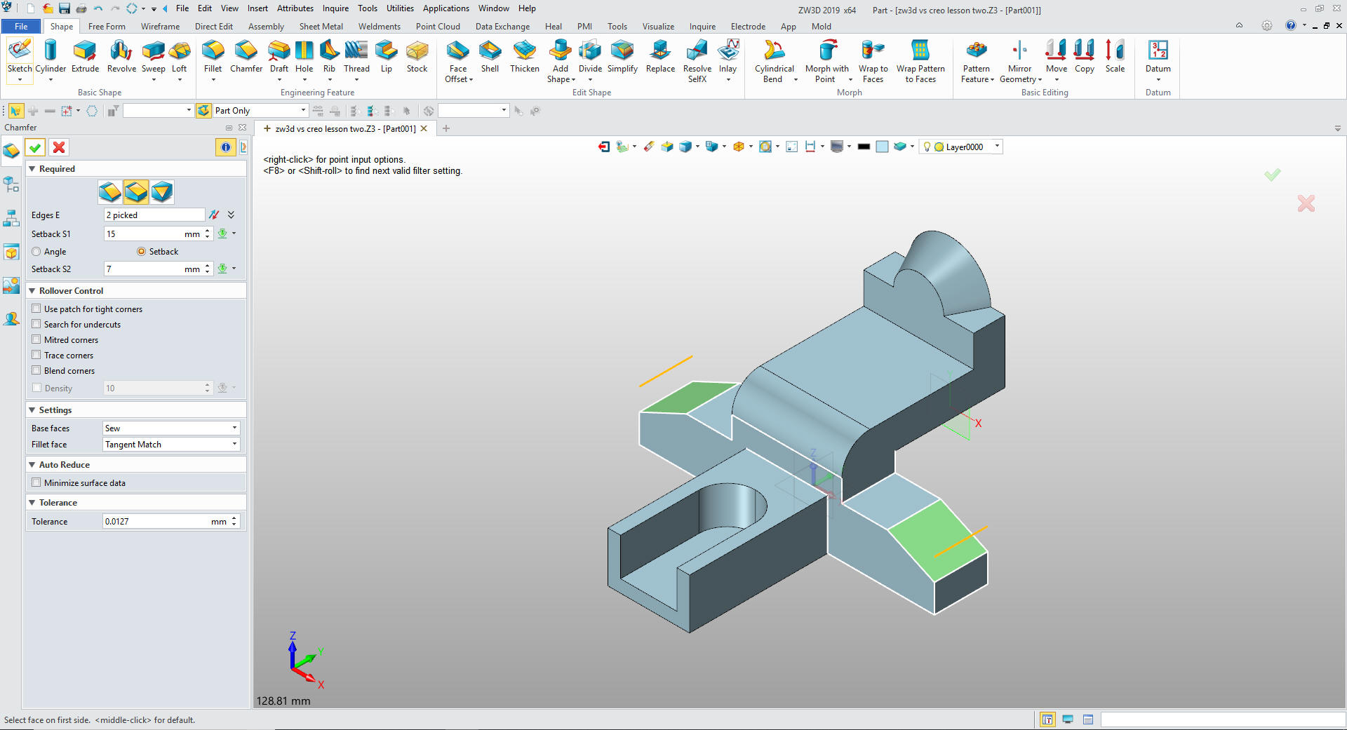
Again we have an option to use features instead of making it
part of the sketch. We put in the large fillet, then chamfers using
the Asymmetrical Chamfer. I have done this all of my solid modeling
life, over 24 years.
The Creo presenter did use the fillet
command for the large fillet? So he is aware that they are
available.
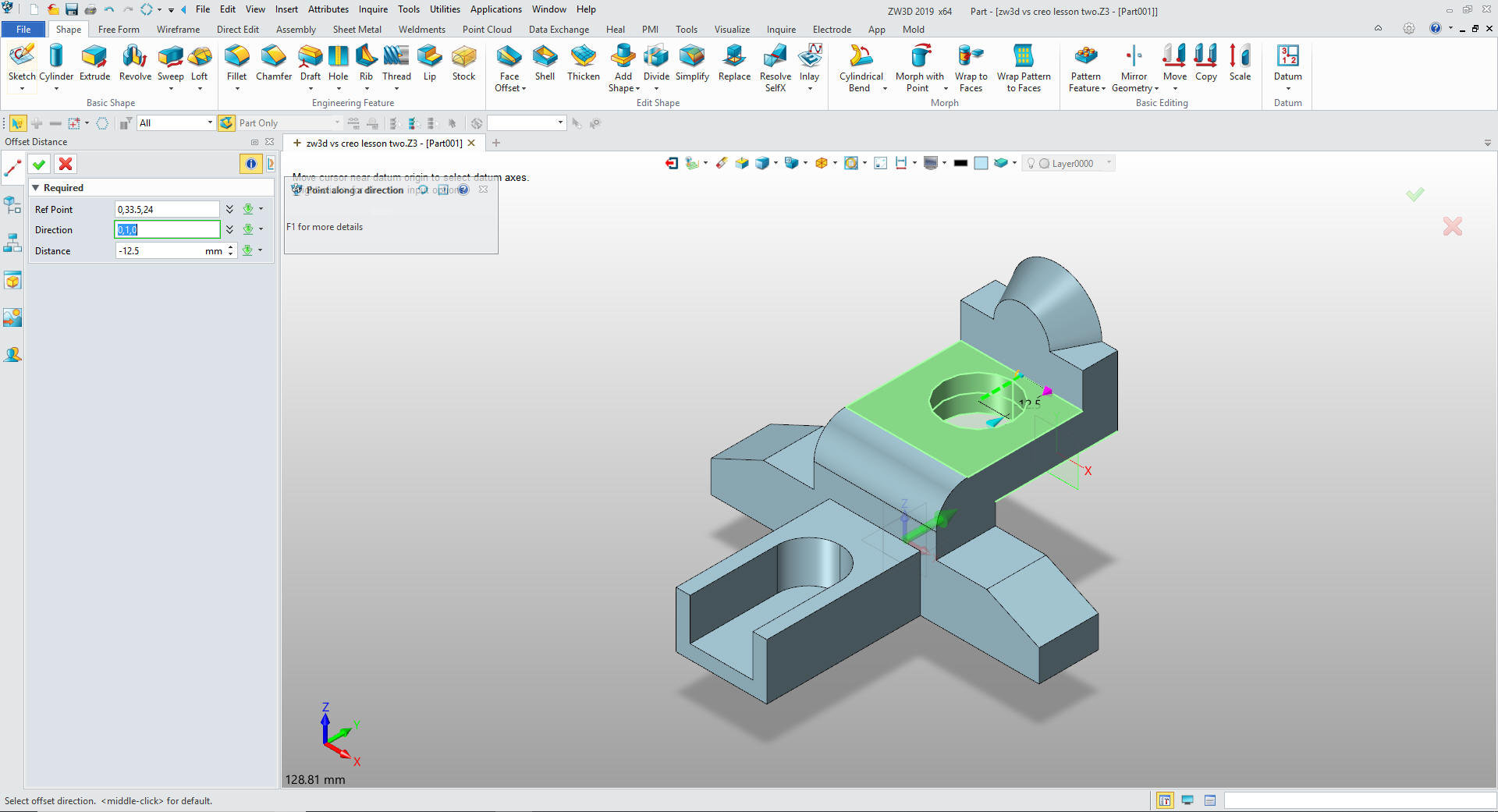
Now
for the 20mm hole. We select the cylinder primitive, select the
alignment plane and offset the distance from a reference location in
this case the mid-point of the front face of the aft block.
We
are done with the part. You can see the steps it took. One Creo
expert told me in a previous lesson that he could do in in fewer
step, he counted each sketch a step. No concern for all of sketching
including the constraining done creating the sketch. He bought a
seat of ZW3D Standard for his own engineering services. A seat of
Creo was beyond his budget and with the native Creo translator he
had all of his legacy data available.
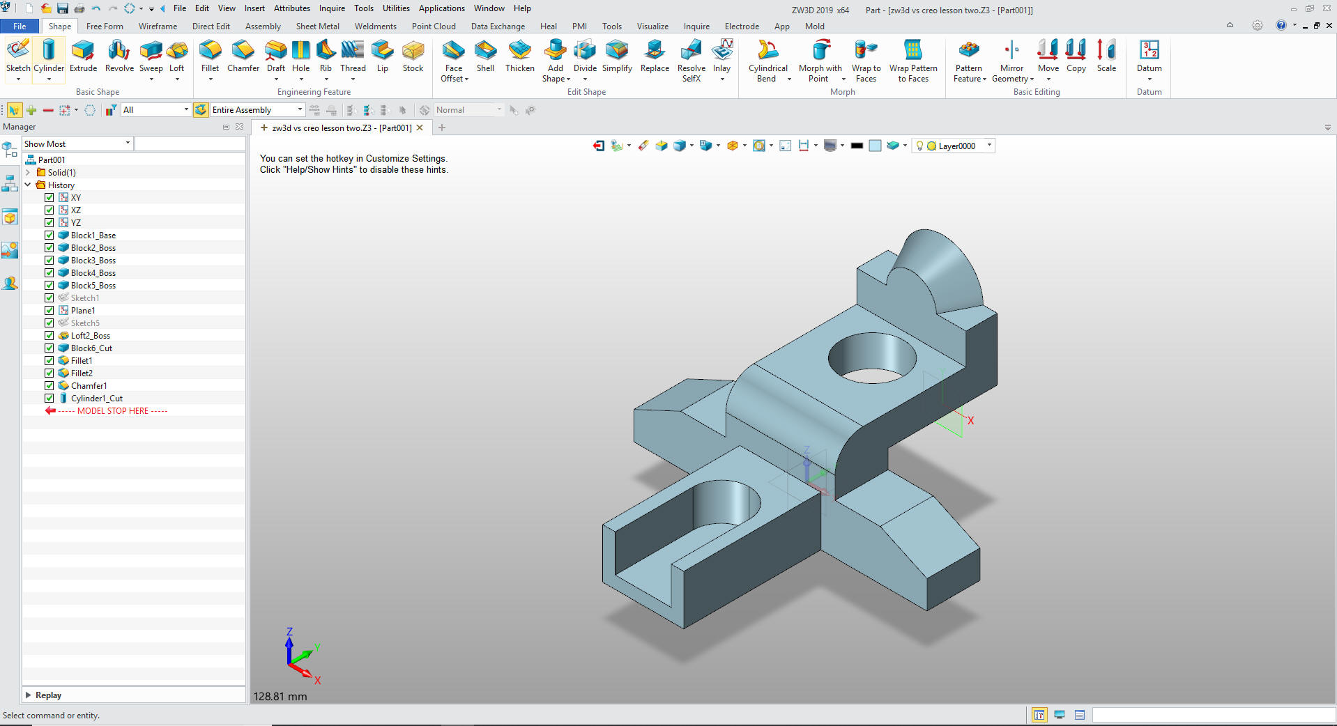
The final part!
Since ZW3D is a sketch based
system we will now create the part with ZW3D using StreamLined
Sketching.
Modeling with
StreamLined Sketching
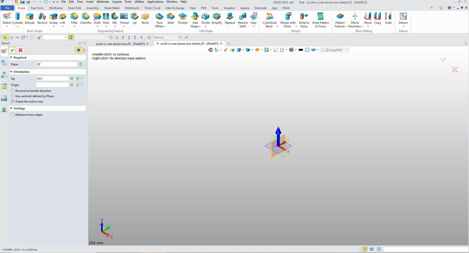
We just open a new file. You can see the
primitive lesson in the other tab.
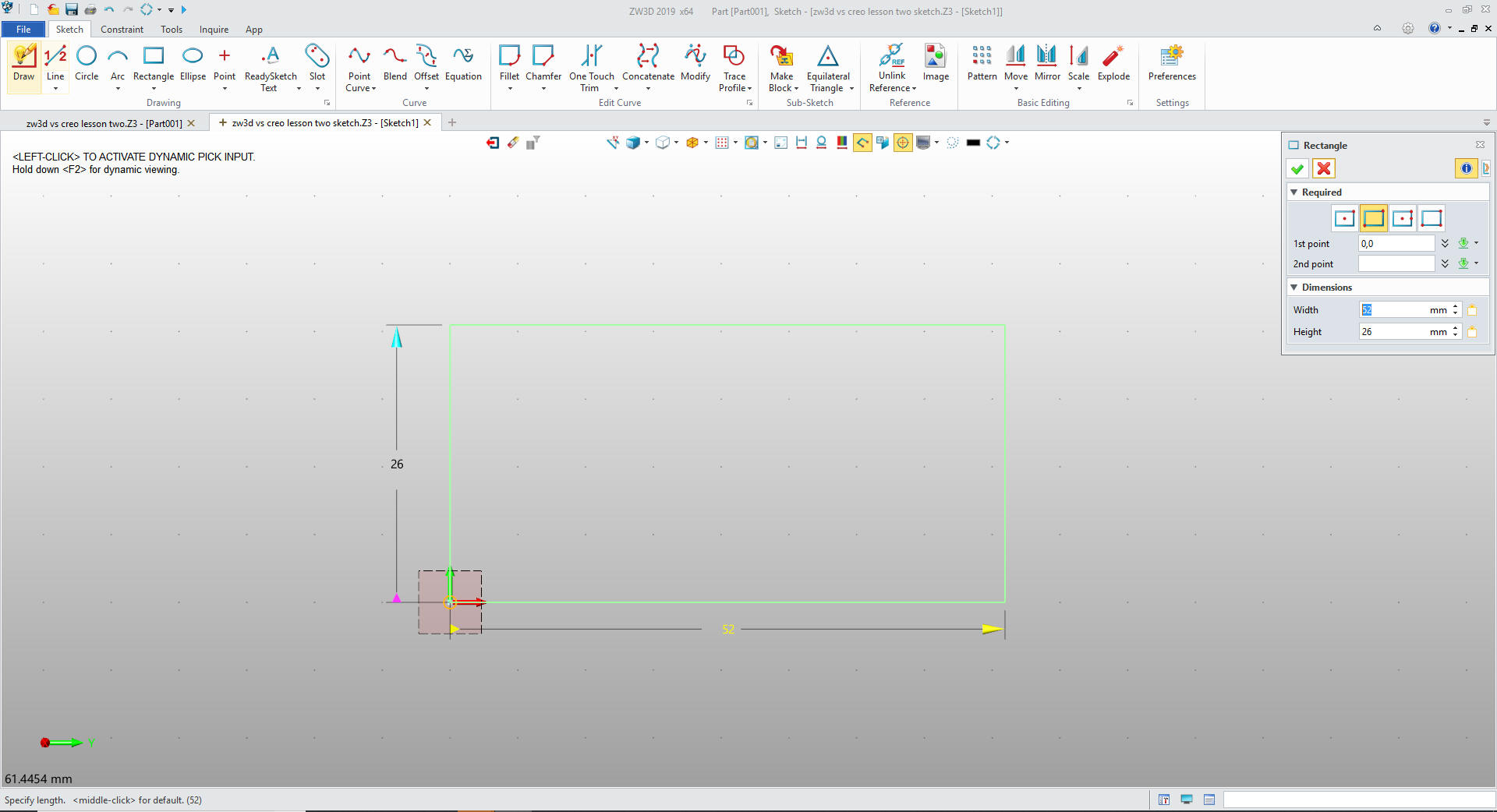
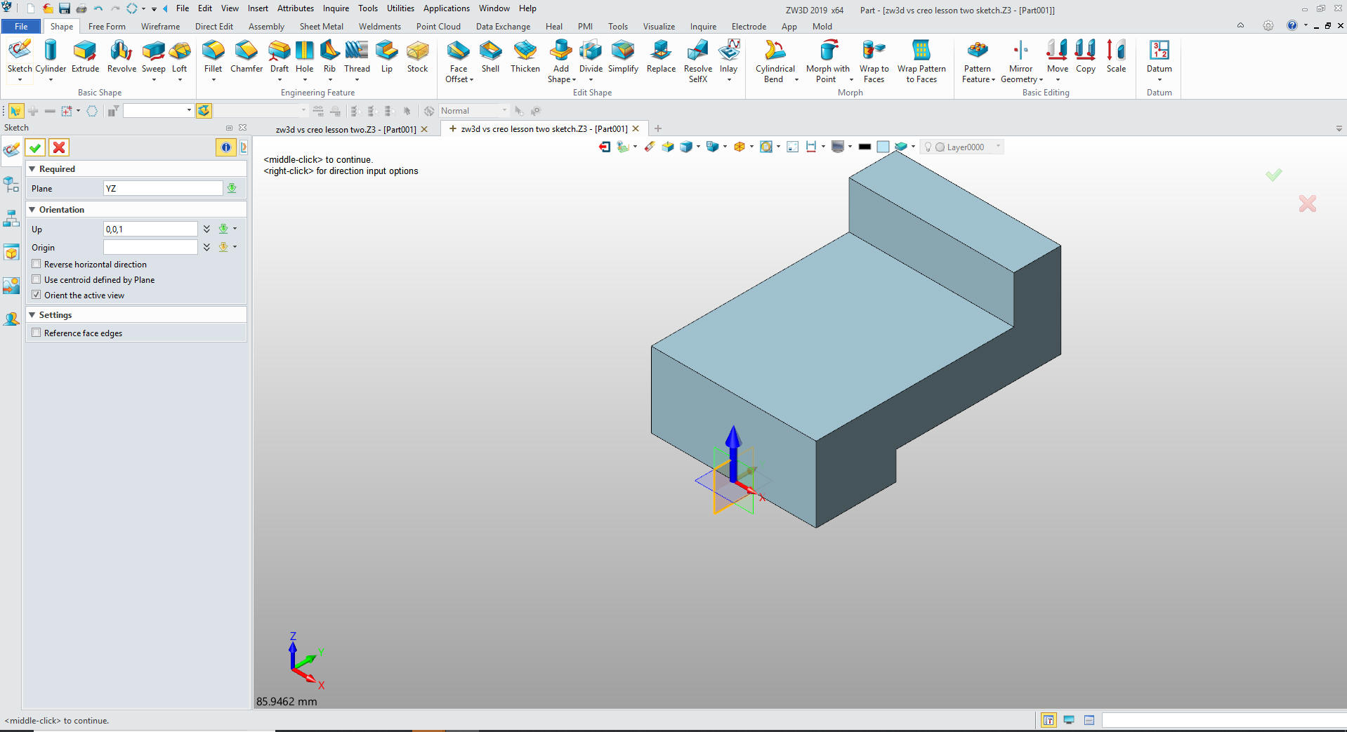
We create a sketch in the YZ plane.
We first create the basic rectangle with the rectangle command.
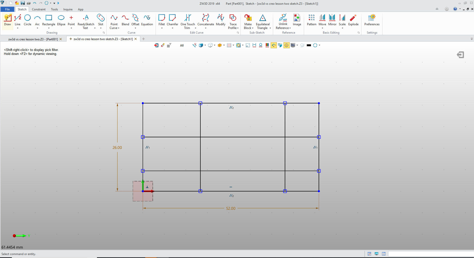
Then the relevant offset lines.
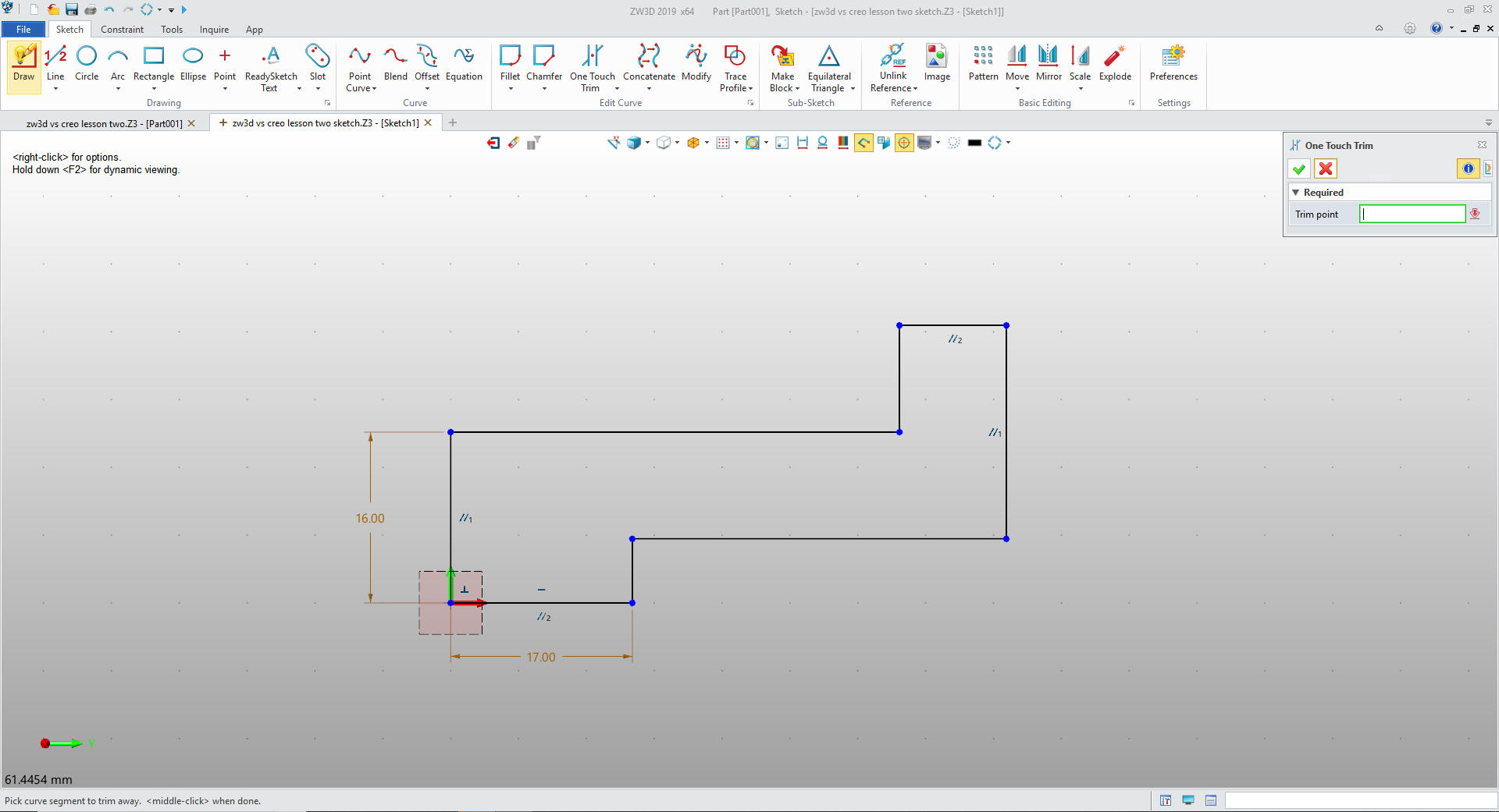
Now we just use the one touch trim command to trim the lines to end
up with our net sketch. Not one constraint used.
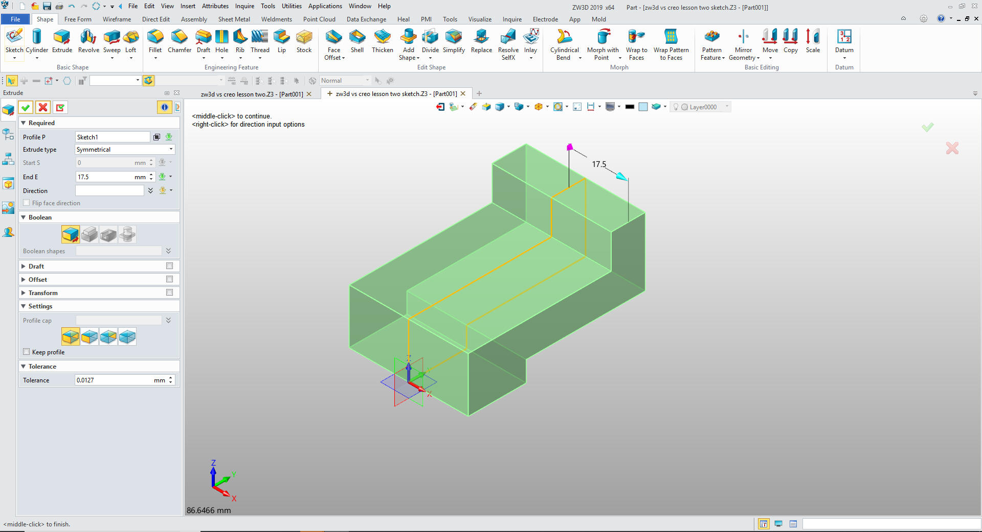
Exit the sketch and symmetrically extrude the feature.
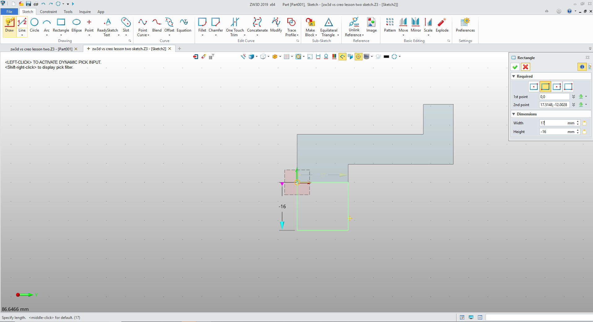
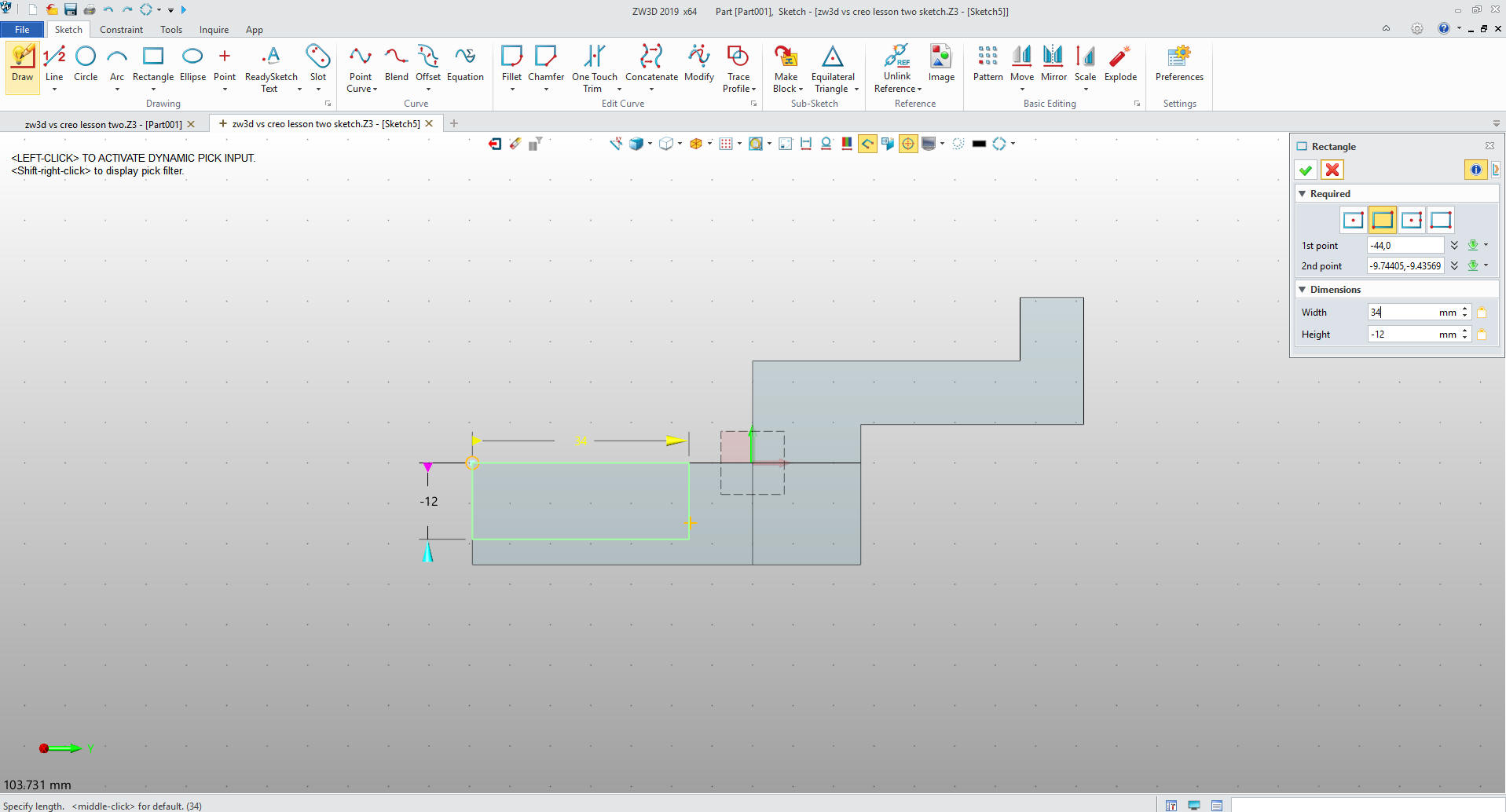
We create another sketch on the YZ Plane.
Again we use the rectangle command.
Size the rectangle in the command. No constrain dimensions.
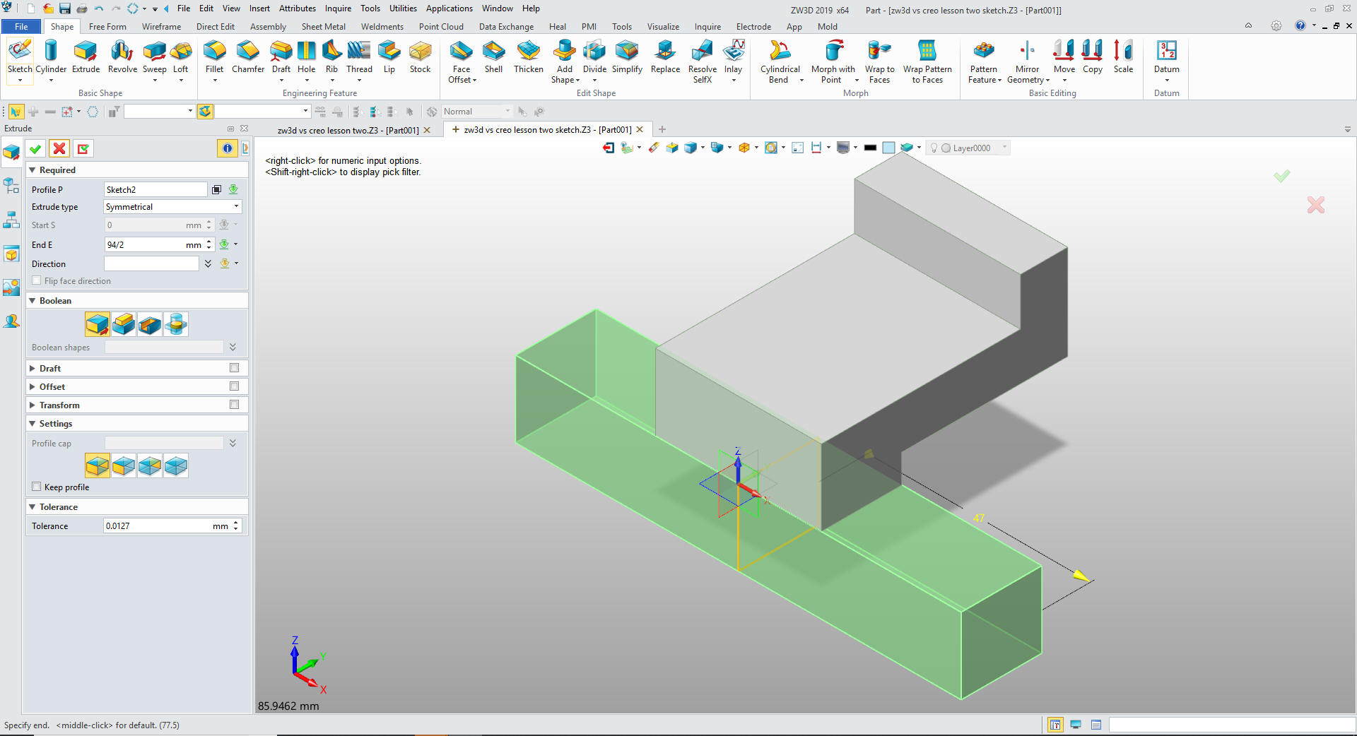
We symmetrically extrude the sketch
and select the add option.
One
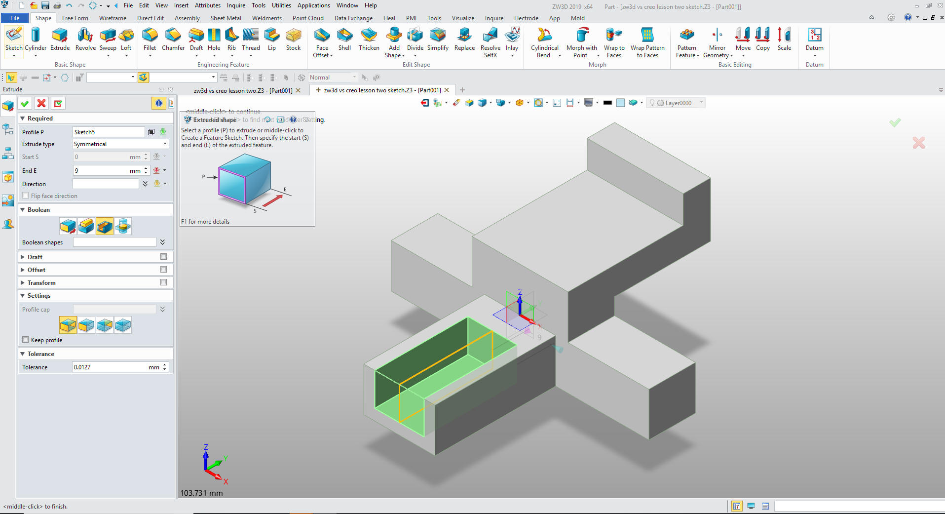
more sketch on the YZ plane. We again use the rectangle command
putting the length and height.
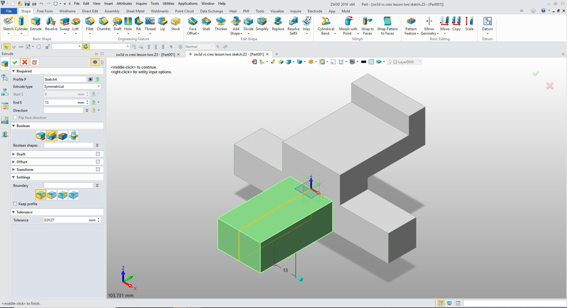
Exit the sketch and extrude the rectangle.
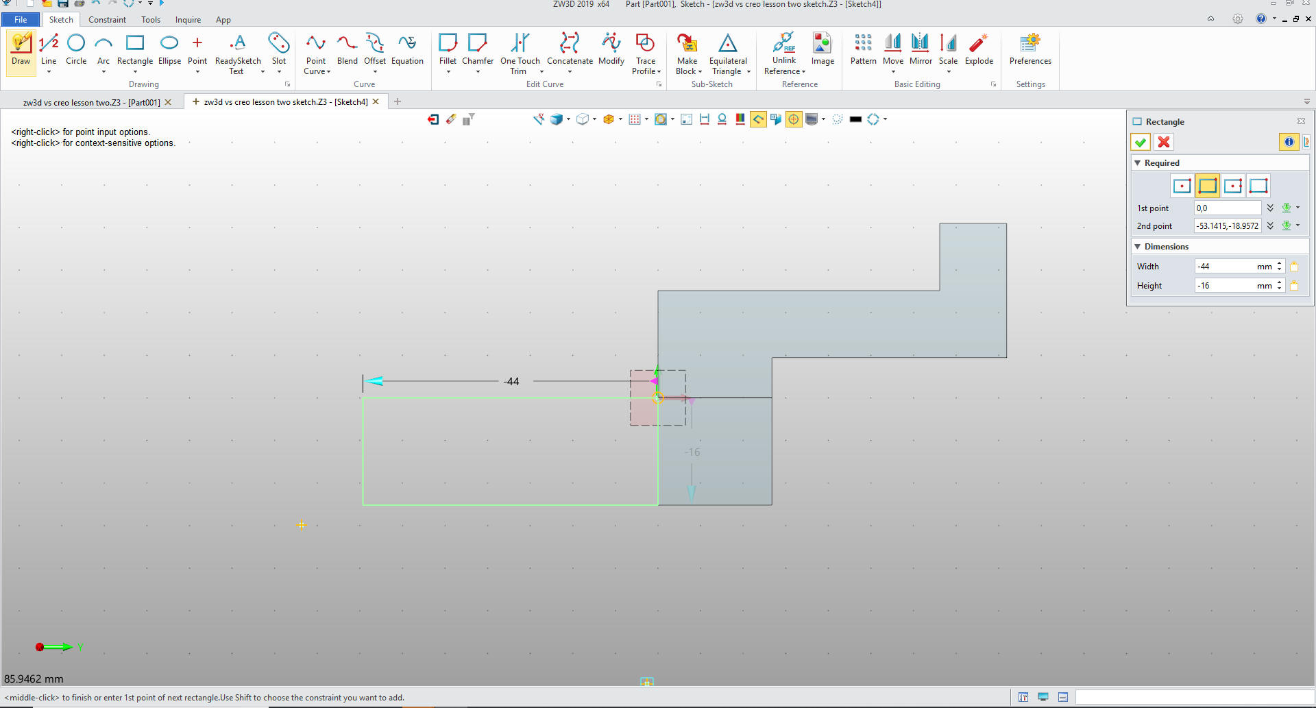
We now create the last sketch again on YZ plane and
create the last rectangle.
We extrude and set the function to remove.
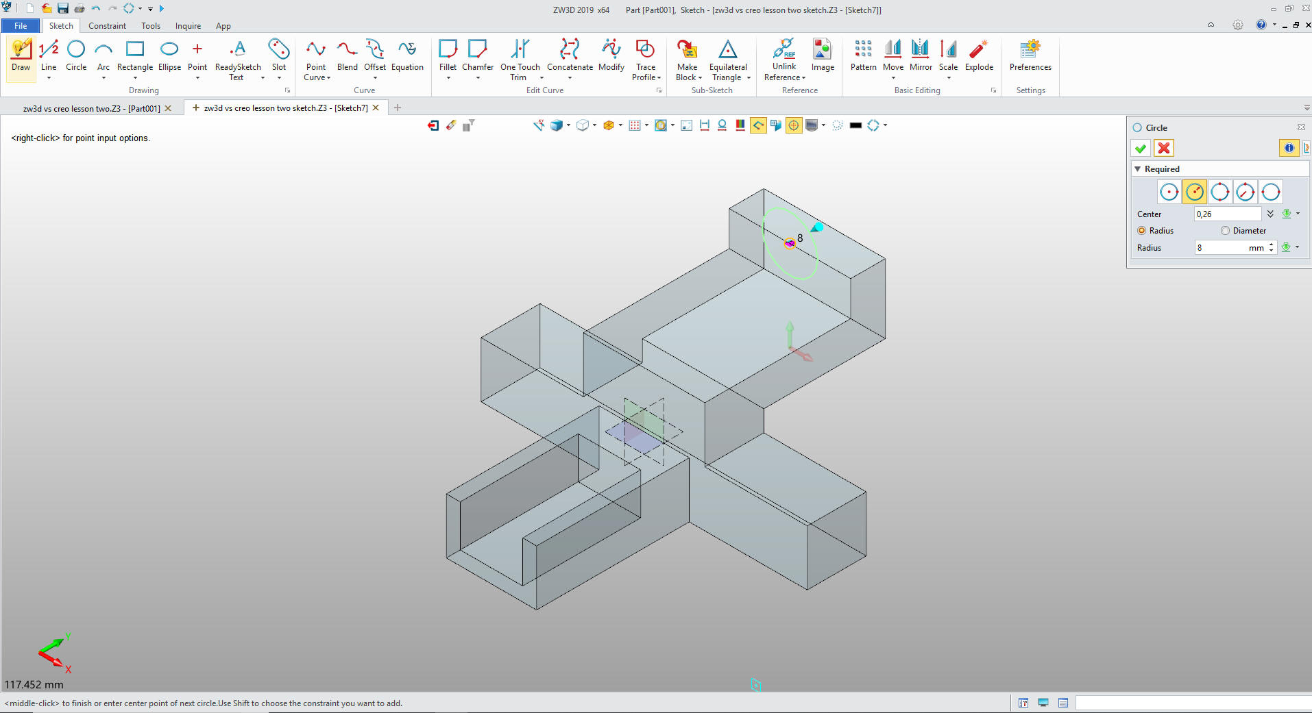
Now for the small lofted feature on top.
We
create the first sketch by picking the front face of the aft block.
We create the first circle for the loft. ZW3D automatically
recognizes the mid-point on the the upper edge.
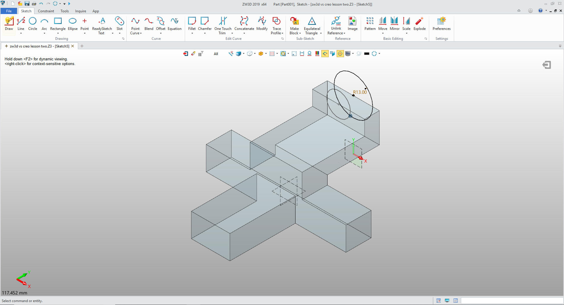
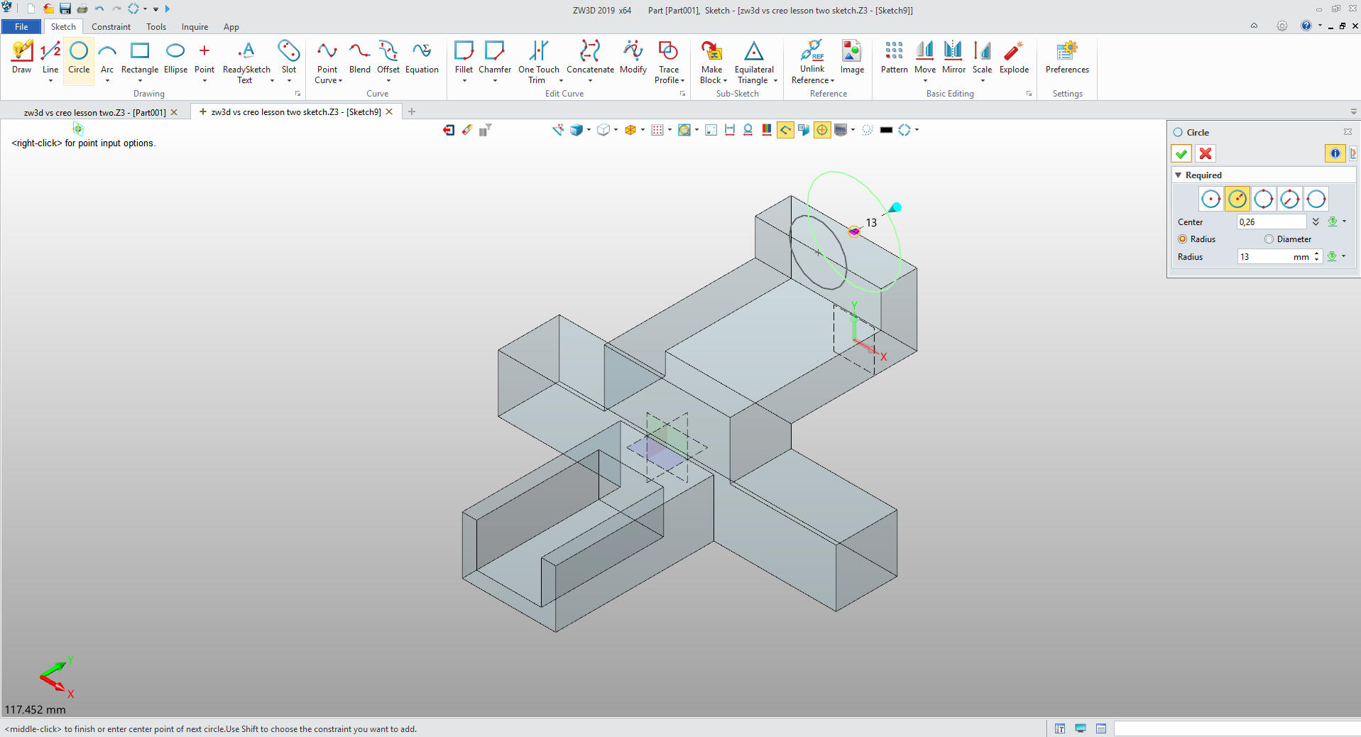
We create a plane on the aft face in the same orientation and create
the sketch and the R13mm circle.
As I did above, there is no
need to create semicircle arc since it is going to be added to the existing
part and become an integrated feature.
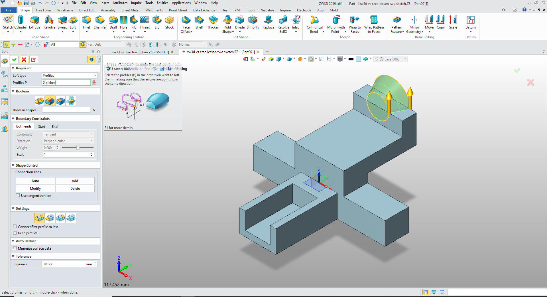
Now
for the loft command, we just pick the two circles, select add.
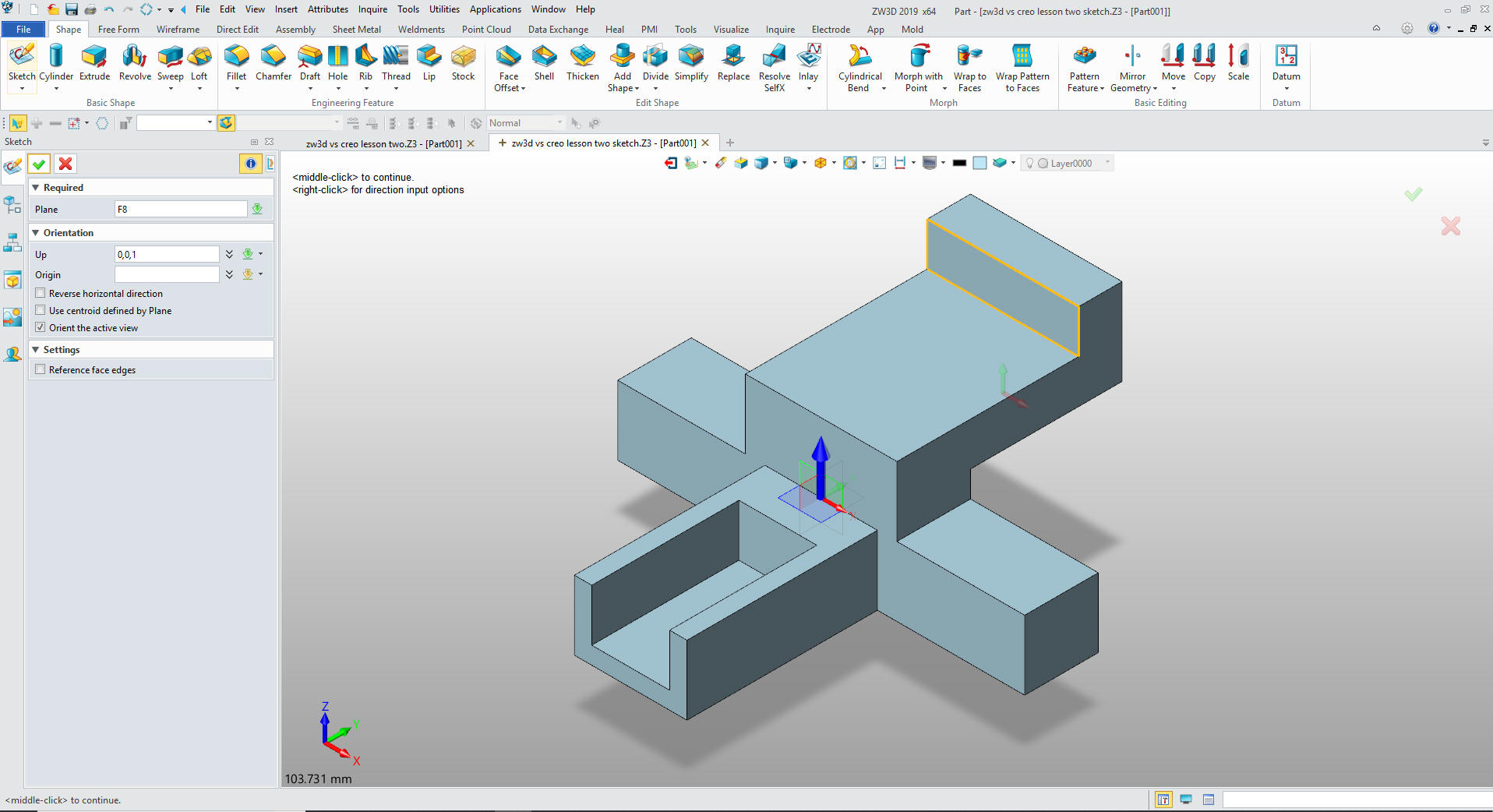
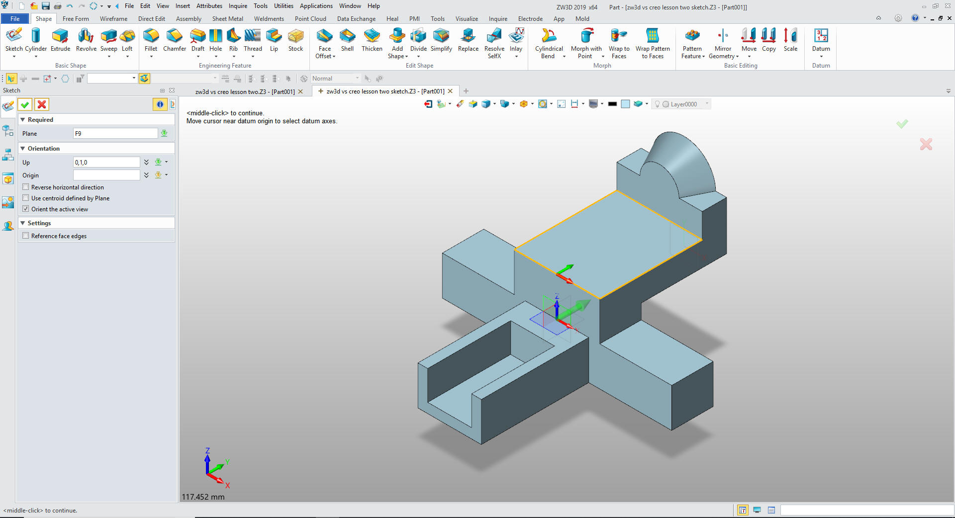
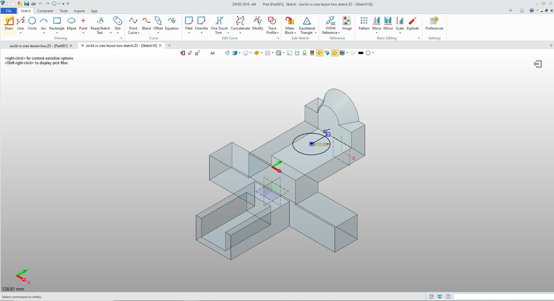
Now for the top hole. We create a sketch on the top face and set the
up direction.
We
create the 20mm circle but putting in a 12.5 vertical line to
reference the location of the enter of the circle. We delete it
before we save the sketch.
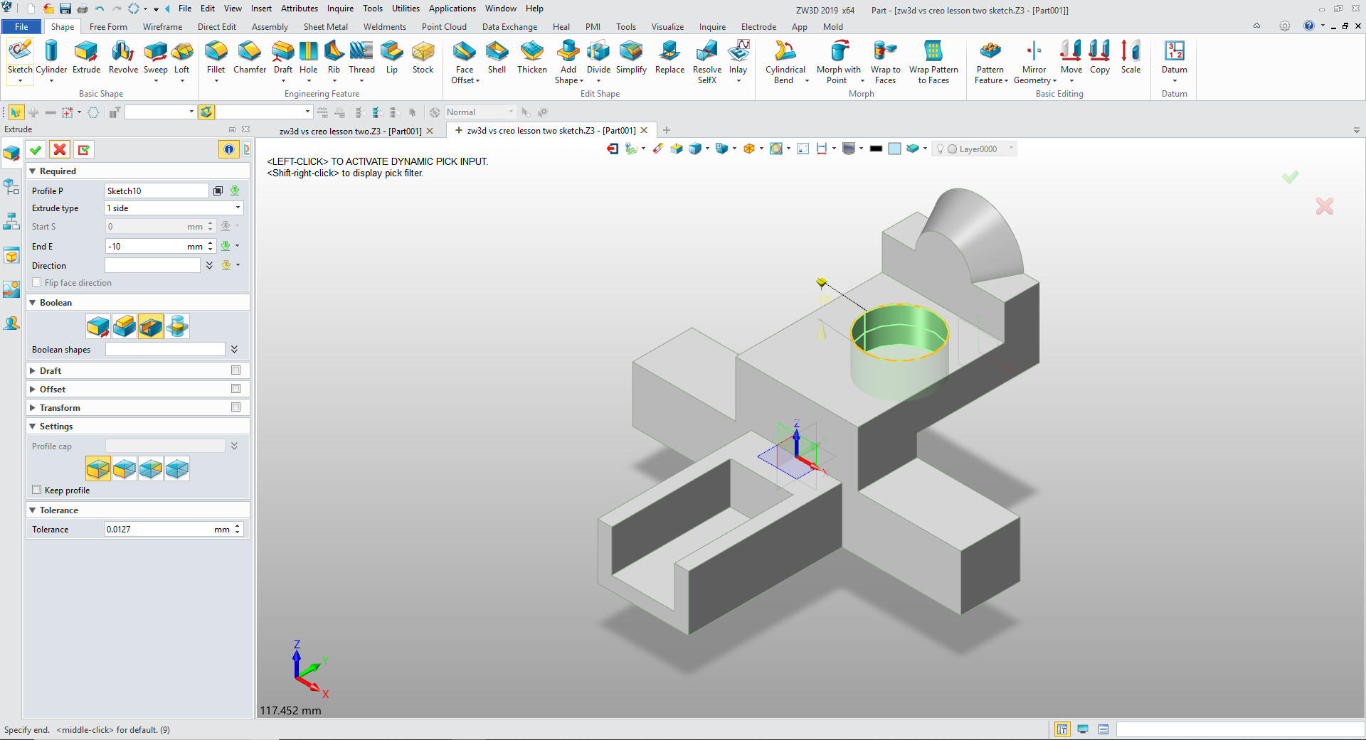
We
exit the sketch and extrude the circle setting it to remove.
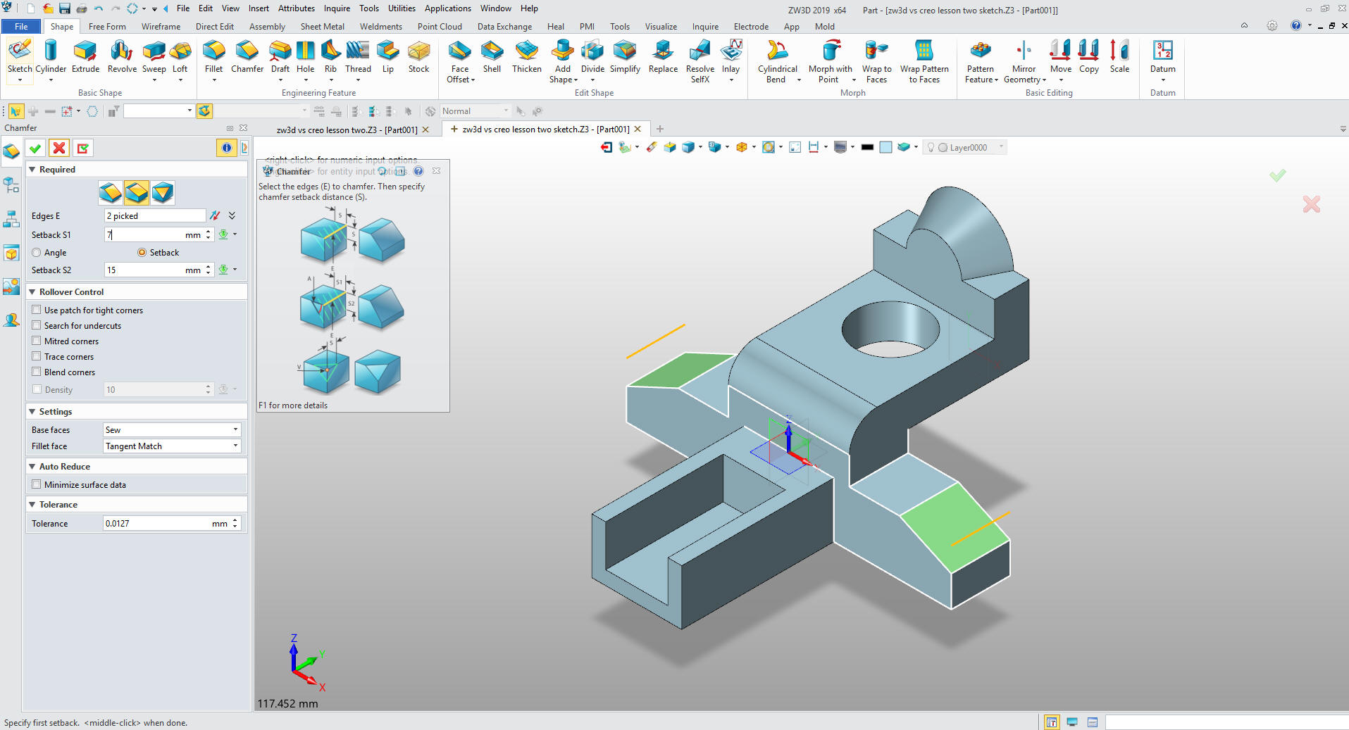
Again
we have an option to use features instead of making it part of the
sketch. We put in the large fillet, then chamfers using the
Asymmetrical Chamfer. I have done this all of my solid modeling
life, over 24 years.
The Creo presenter did use the fillet
command for the large fillet? So he is aware that they are
available.
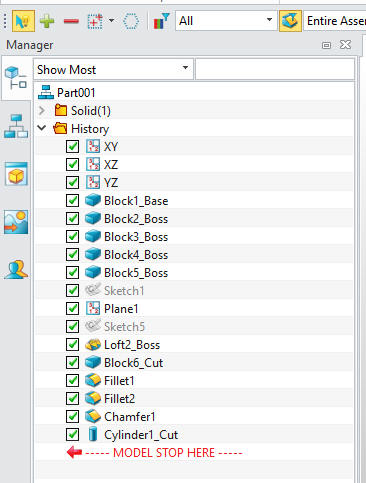
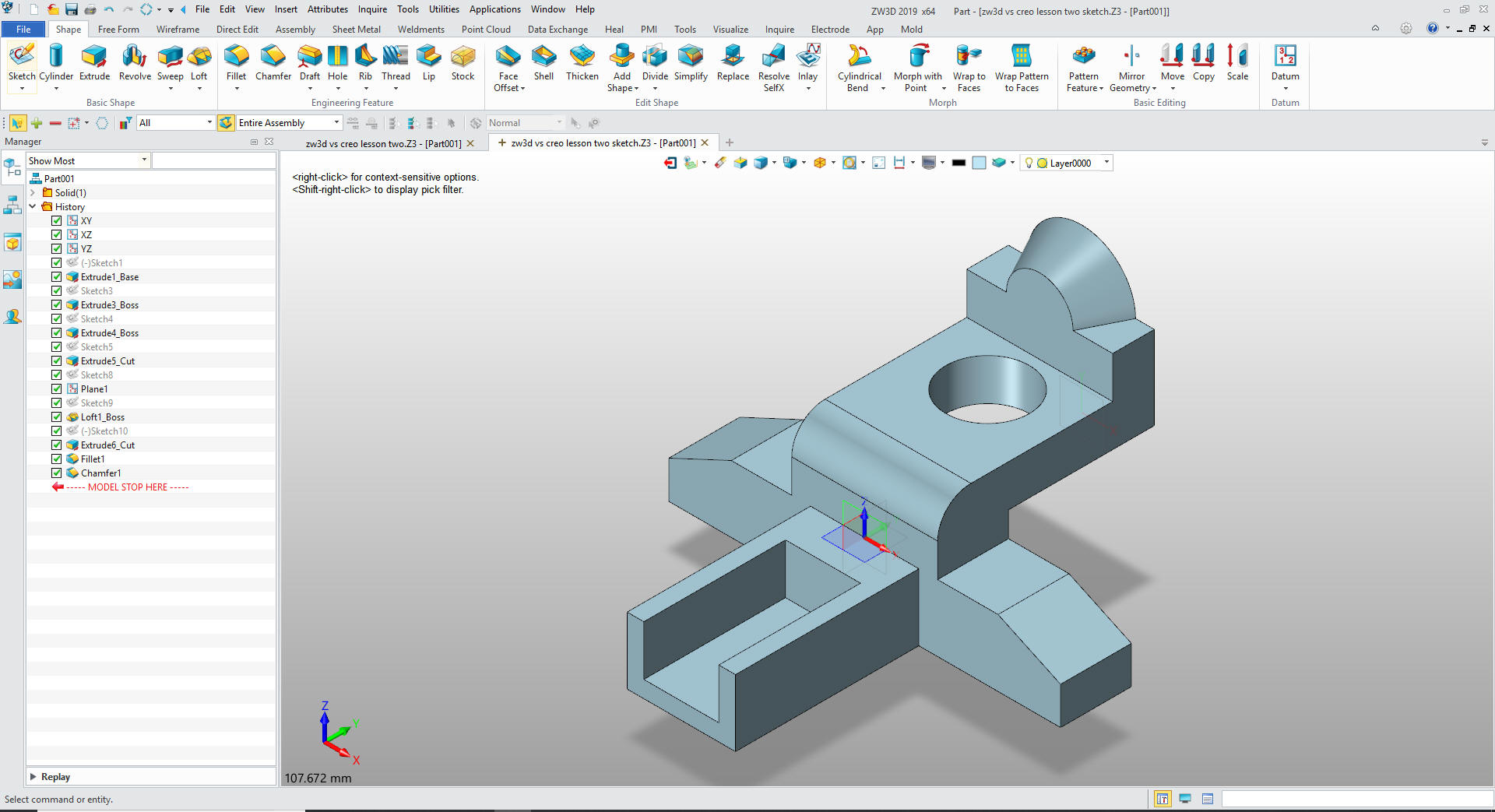
The final part. The history tree does not reflect the lack to
constrained dimensions that increases productivity of Streamlined
Sketching available in the more Soldworkish clones.
You can see the two process that ZW3D offers are both hugely
more productive than the tedious constrained based sketching.
Give me a call if you have any
questions. I can set up a skype or go to meeting to show this part
or answer any of your questions on the operation of ZW3D. It
truly is the Ultimate CAD/CAM System.
If you are interested in adding professional
hybrid modeling capabilities or looking for a new solution to
increase your productivity, take some time to download a fully
functional 30 day evaluation and play with these packages. Feel free
to give me a call if you have any questions or would like an on-line
presentation.