These articles started out as
product comparisons, but quickly turned into a study in 3D modeling
techniques.
I am not sure if it is due to these
exercises but I have replaced a few Fusion 360 with ZW3D. Listen to
what one of the fellows said.
"We spoke a year and a
half or so ago about ZW3D. I took the Autodesk Fusion
360 but am becoming increasingly unhappy with it… It’s not very
productive for me, just too slow and cumbersome to get things done
quickly. On on the strength of your recommendations I am ready to
give ZW3D Standard a shot, probably as a rental for the first year.
Bottom line is,
Fusion 360 is “free” but not really free… I am finding that the
slow, clumsy pace of design with it is counterproductive… time is
money."
Thanks much, Brian
Again I
follow up my IronCAD lesson with a ZW3D lesson. This is a bit different and quite
simple. ZW3D has Boolean primitive shapes you can use, nothing like IronCAD
but offers an added flexibility.
I saw the
following video challenges on LinkedIn and thought I would give them a
try on IronCAD. I got a great response and decided to do it in ZW3D.
I was very familiar with the parts and did it a bit easier. It shows
more the difference in the level of the 3D CAD experience than the
CAD system itself. You can
Download ZW3D and give it a try.
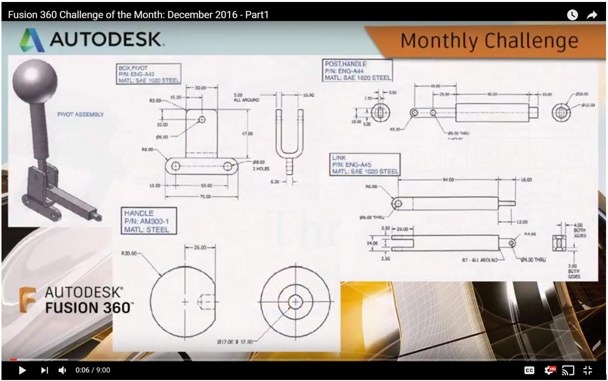
Here is the drawing.
ZW3D is very similar to Fusion 360 and the Pro/e
clones with differences that make it much more streamlined. It is very easy for those users
to get up and running with ZW3D. The unique benefits over the other systems
is the multi-object environment, for easy top down design and the the integrated drawing. You can
do complete projects (parts, assemblies and drawings) in one file.
Imagine how much this would simplify PDM?
ZW3D vs Fusion 360
I would do a
video, but I really am not good at it. So I will show you step by
step. I will try and get ZW3D support to create one. They are
very good.
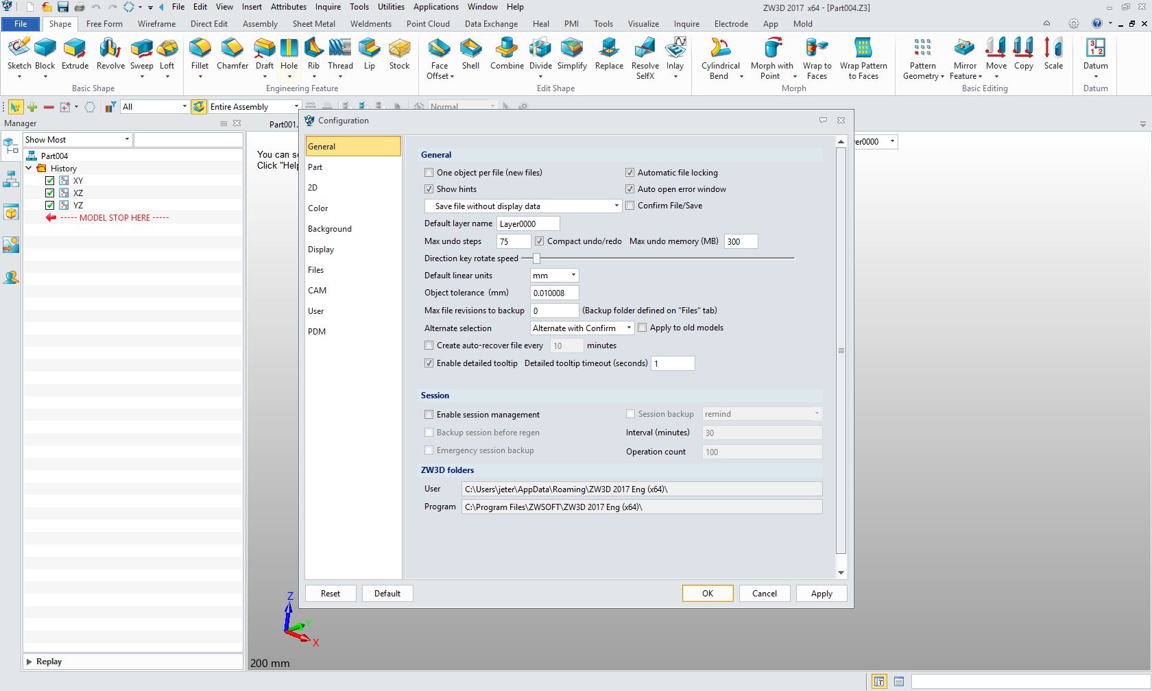
Here is ZW3D. We set the units to
millimeters.
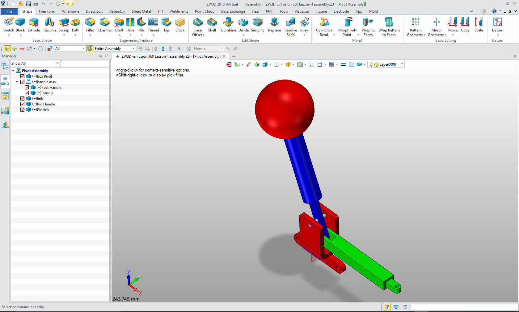
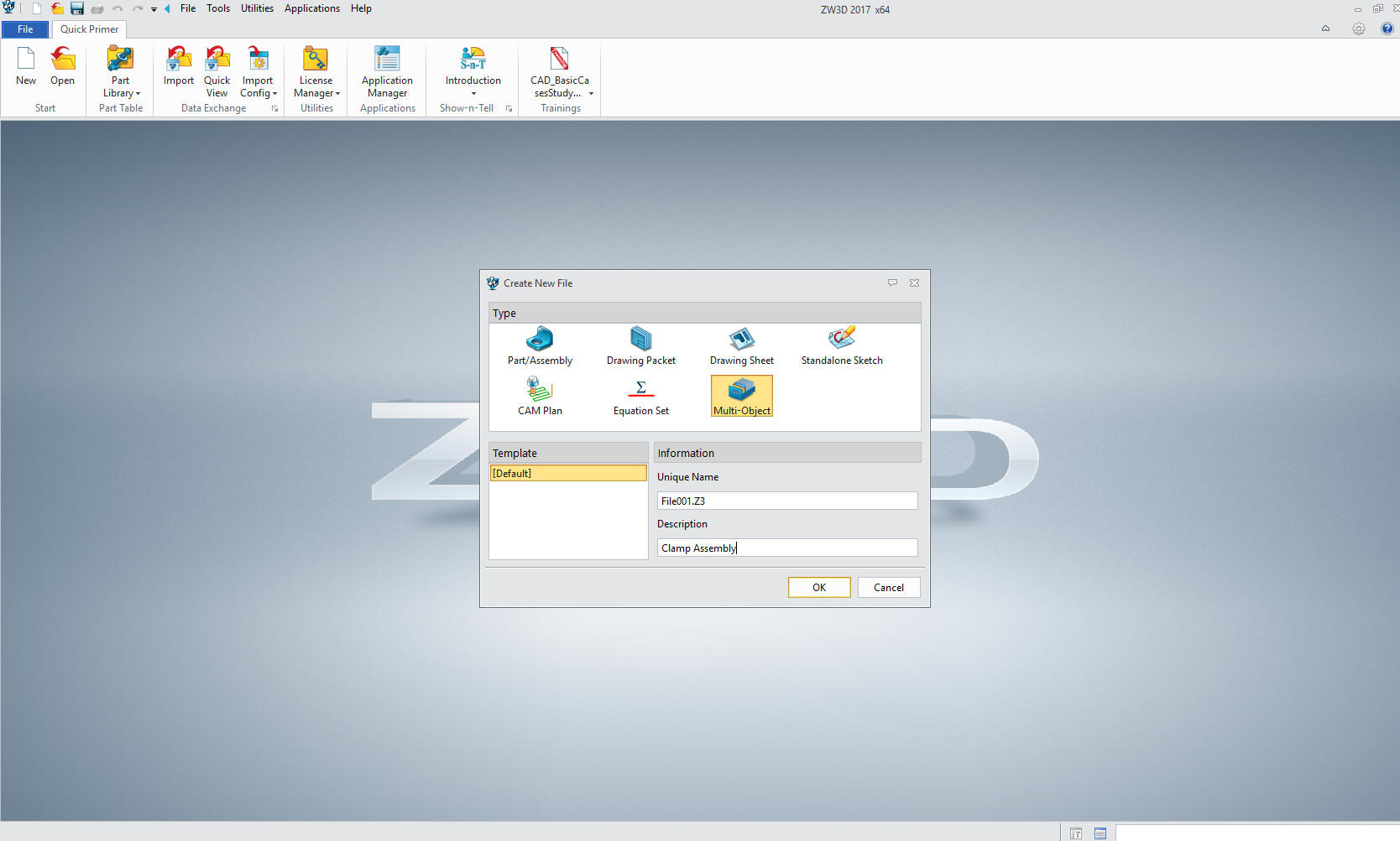
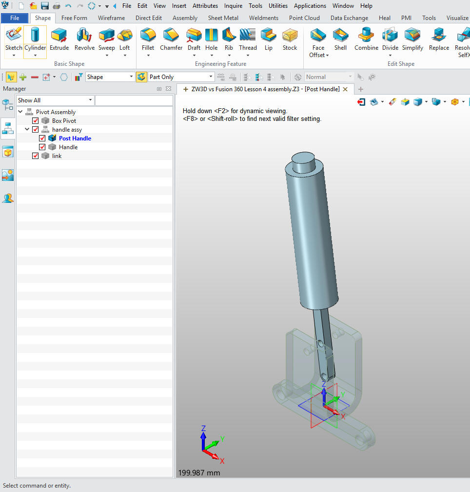
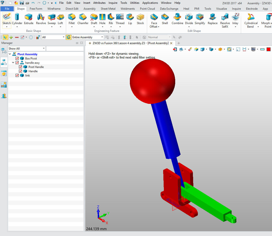
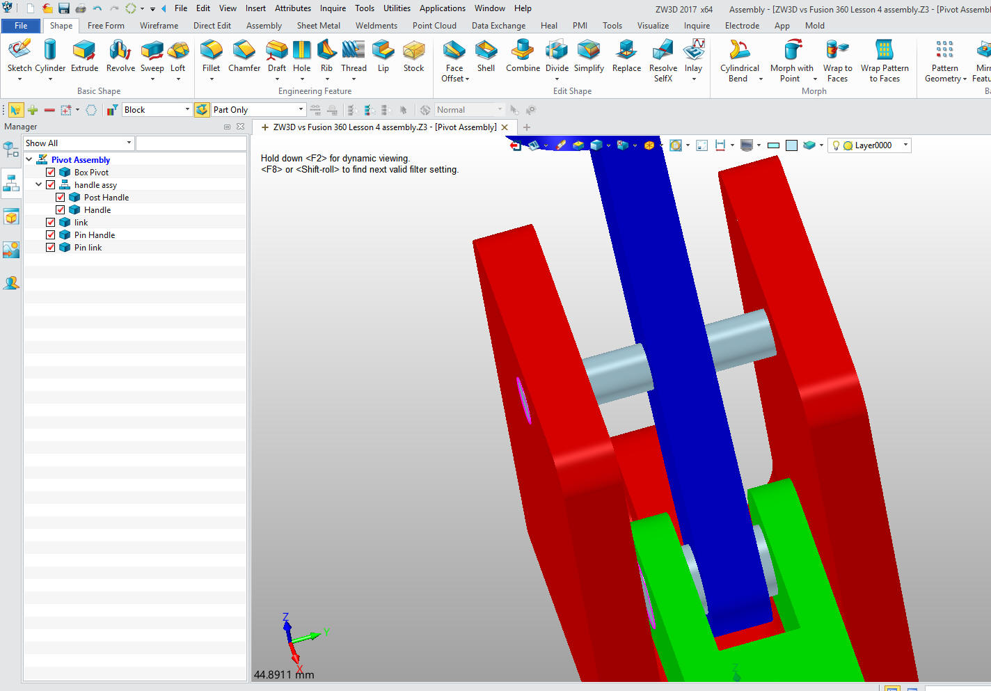
We will create a multi-object file with the
top assembly called the "Pivot Assembly". Like Fusion 360, ZW3D allows all
of the parts and assemblies in one file. Neither one are true single
model environments since they have a top assembly. Even though parts
are separate they still are available for top down or in context
design. We did the parts in context for mostly just location,
eliminating the need to mate them.
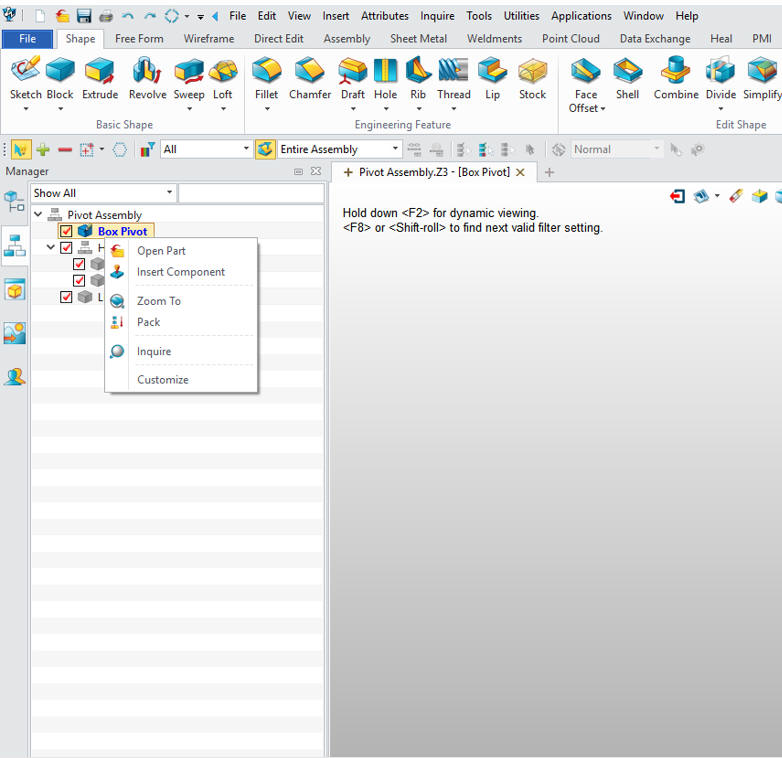
We now insert our components. We do not have
to have any graphics to do this. They are basically place holders
until we create the parts. We can add parts and subassemblies at any
time.
We will make the Post Handle and Handle an assembly. Imagine how much easier this is as compared to the clunky process of
the other Pro/e clones that force you to have external parts?
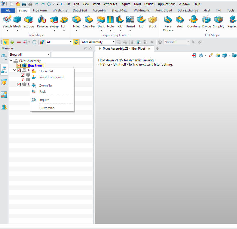
Now that we have all of our parts defined we can start creating
the part. We will open the Box Pivot.
I have to admit
that the Fusion 360 presenter made this part incredibly complicated.
If this is the way 3D CAD design is being done, we are wasting
thousands of engineering hours.
Fusion 360 could be used
much, much more effectively used with feature based design. It looks
like many are stuck in this wasteful sketch, sketch, constrain,
constrain world. Even when the system offers more productive
options, they seem to stick with this convoluted level of design.
You can see how I do this simple part in ZW3D which is very similar
to Fusion 360. I suppose my familiarity with feature design started
with my past experience, first 2D/3D wireframe, Boolean and direct
edit design. When I finally did go to history, it was with IronCAD
where history and direct edit are completely integrated.
This is mostly design technique, not so much ZW3D. While we
do start by creating a Boolean primitive block, the basic functionality of this
design process is in all systems.
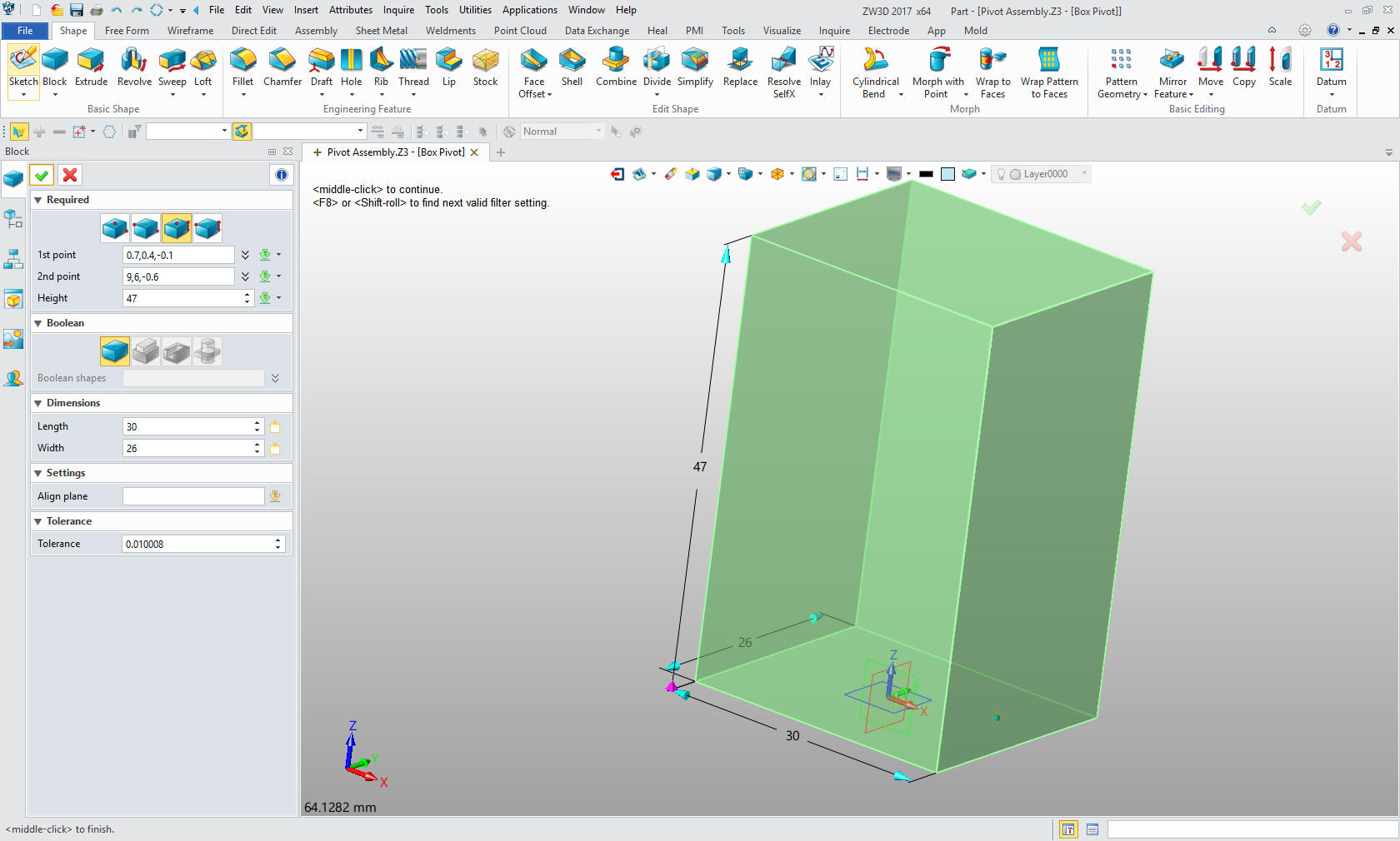
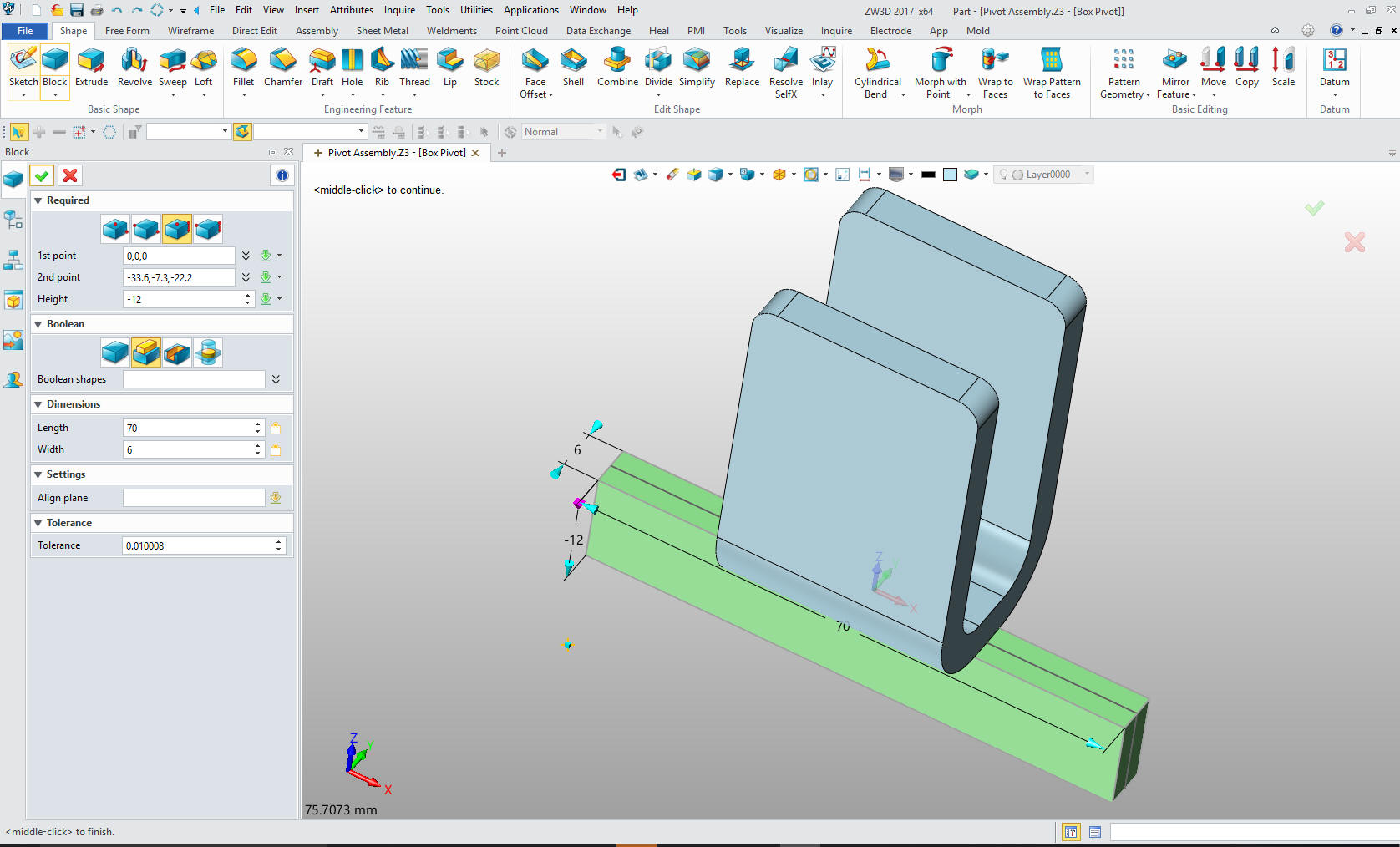
Let's start with the "Box
Pivot" We select a block shape and locate it at X0Y0Z0 and size it.
This part is so
simple that it strains all credulity to watch how the Fusion 360
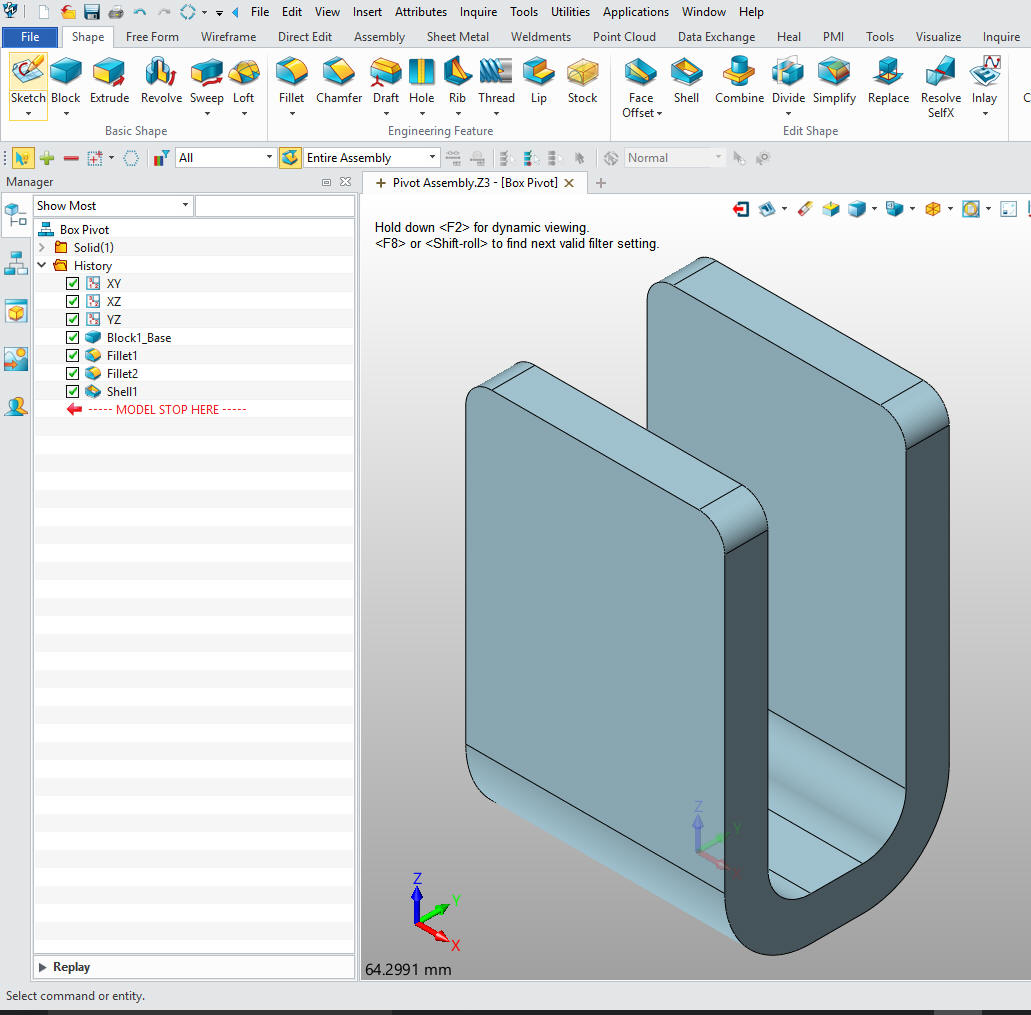
fellow modeled it. We will put in the blends and shell the part.
That's it. You can see the 3 steps to do this process in the history
tree!
Again we avoid sketching by creating a block at X0Y0Z0 and
sizing the block.
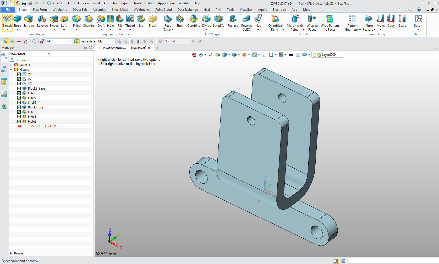
We
create the fillets and add the holes. Nope, no sketching, in fact,
there was not one sketch needed to create this part. We are done
with the Box Pivot
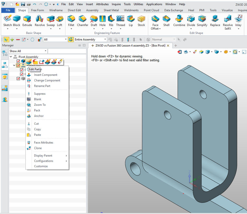
We will
edit the Post Handle in the Handle Assy. This allows us to create
the part with the other parts available for reference. This is
called top down or in context design.
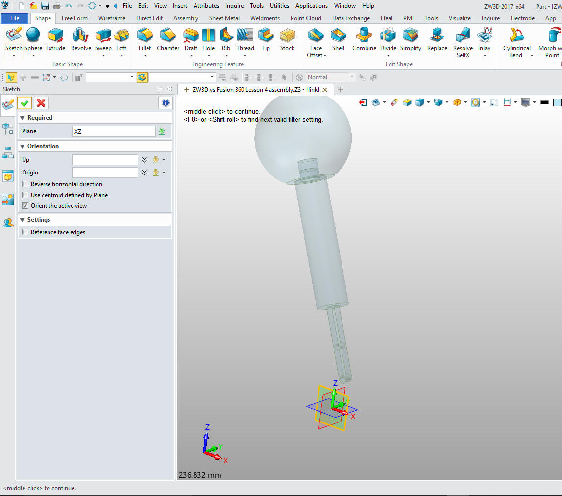
I will
create a sketch on the XZ planne
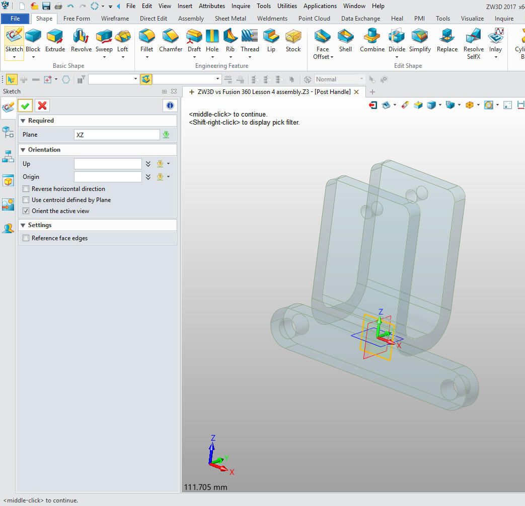
We now
extrude the bottom part of the Post Handle.
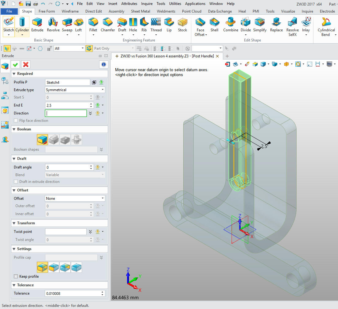
Now add the two Boolean cylinders and we are finished with the part
and we rotate it.
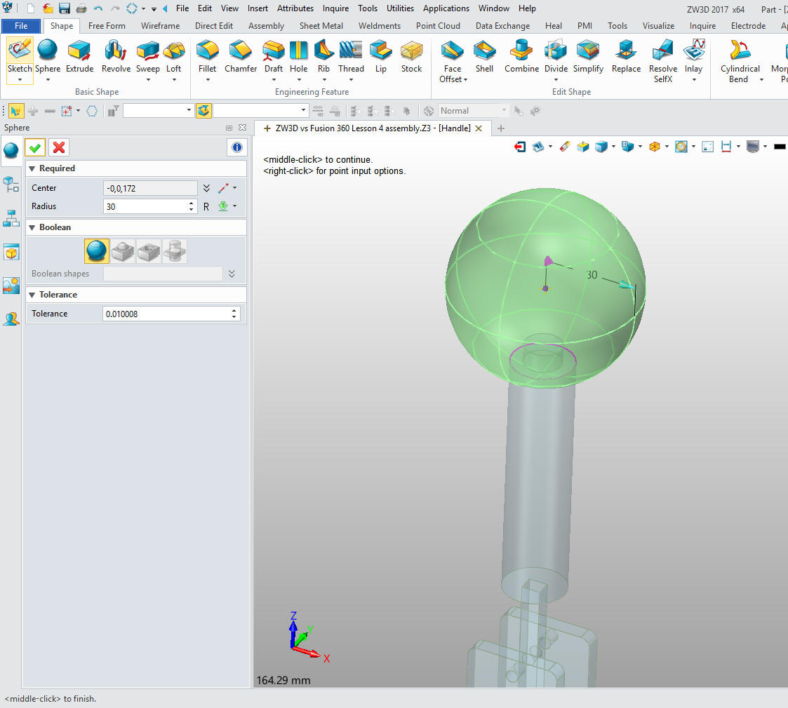
Now
the handle. We create a reference circle on the mating face. We drop
a Boolean sphere on the center and offset 26mm and set the radius to
30mm.
We create a rectangle in the sketch and then extrude. The size
is not important since it is to just cut the bottom face.
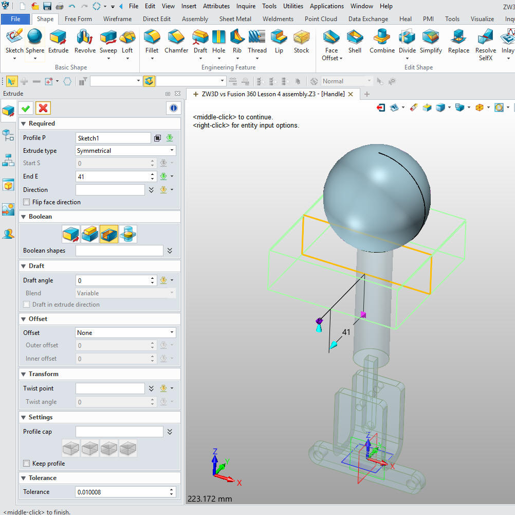
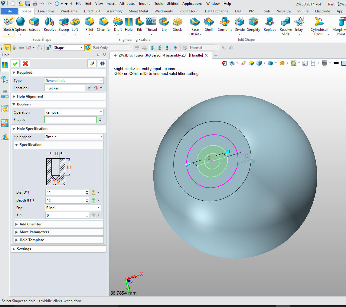
We
then put the hole in the bottom of the handle.
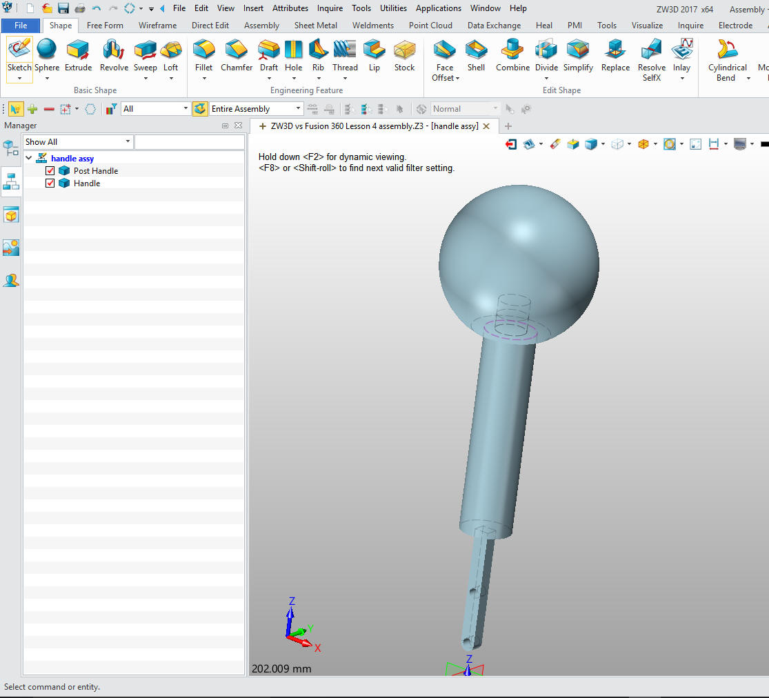
We are
now done with the Handle Assembly
Now to create the link. We will
edit the part and have the handle assembly available for reference.
It is nice to have the mating parts available it eliminates the need
to move the part later.
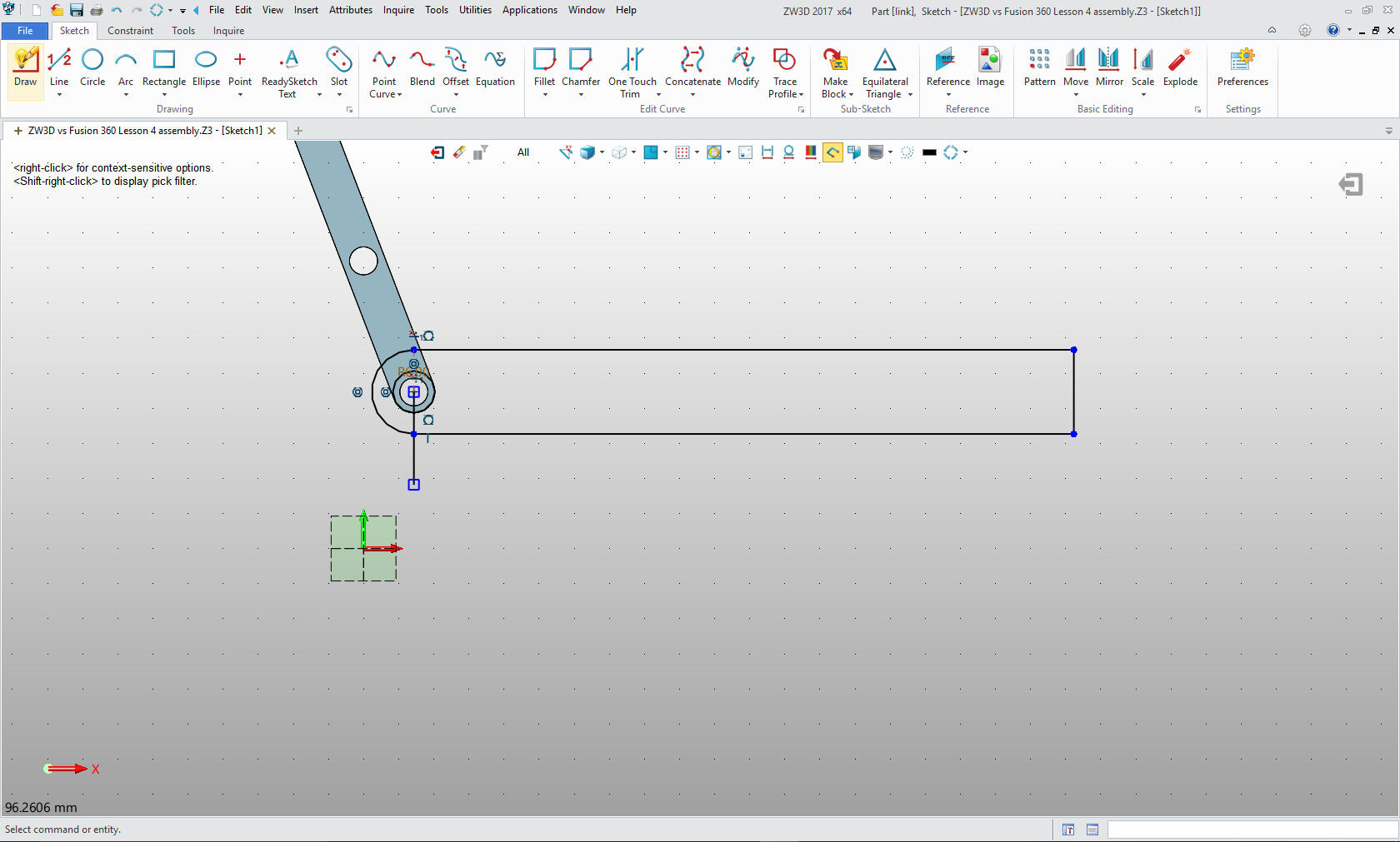
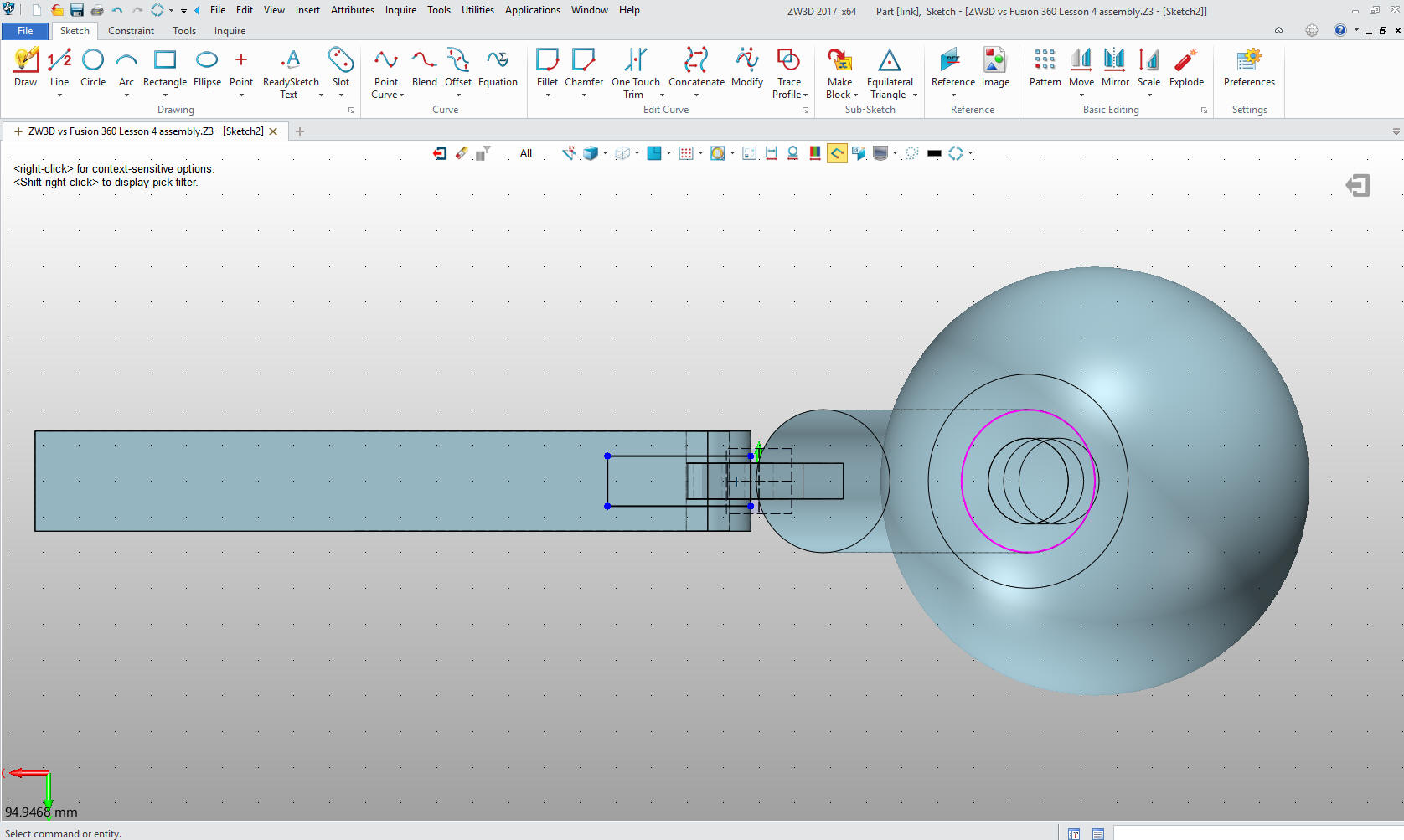
My
sketching is a bit simple I created a reference vertical line in the
center of the existing circle then offset another line 94mm. Then
created the outer circle and created the tangent horizontal lines
and extended and trimmed as necessary. All of the dimensioning must
drive these guys crazy.
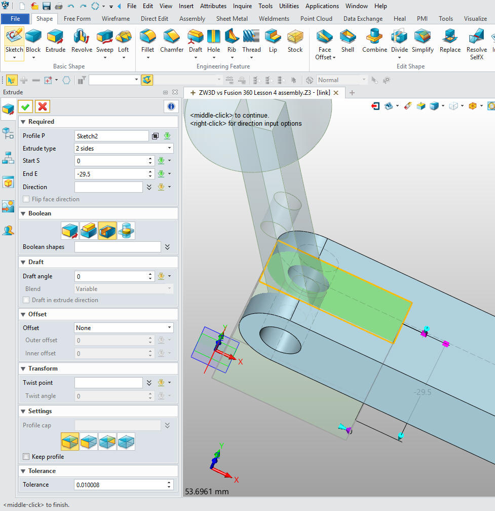
Again I create a sketch by offsetting
lines and trimming with a few projected reference lines. No
dimensions.
Extrude the
sketch.
We drop
a block on the end, size it, put on the fillets and put in the hole
on the center of the fillets.
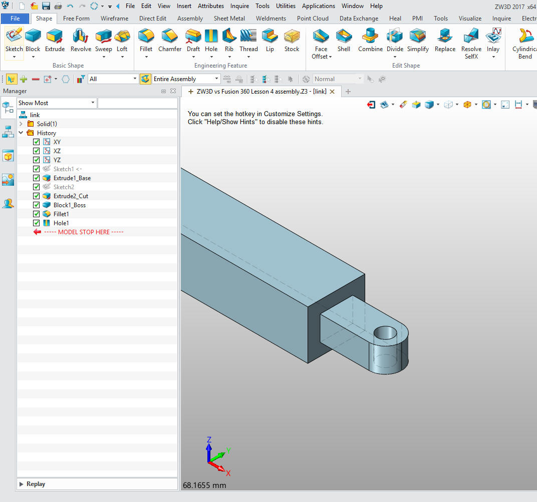
All
done!! Just too simple.
Might as well put in the pins.
It is very important that you look into
how you or your engineers are creating the parts. Streamline
Sketching and Feature Based Modeling is easy to learn and implement.
It, alone, will increase productivity 10X. Now, ZW3D with its unique
history and robust direct edit functionality can increase your
productivity another 5X or more with changes! Again, time is money
in engineering.
More on Streamline Sketching and Feature Based Modeling.
3D Modeling Techniques Defined
To experience this increased level of
productivity, please download ZW3D for a 30 day evaluation. Legacy
data is no problem, ZW3D can read the native files of all of the
popular programs including the PMI data of NX, Solidworks, Catia and
Creo. ZW3D is a great replacement for the subscription only Autodesk
and PTC products.
For more
information of to download ZW3D
Give me a call if you have any
questions. I can set up a skype or go to meeting to show this part
or answer any of your questions on the operation of ZW3D. It
truly is the Ultimate CAD/CAM System.
TECH-NET Engineering Services! | |