ZW3D vs Inventor Lesson 1 Assembly 3D Modeling Techniques DefinedTrue Top Down Assembly/In Context Design vs Separate Part DesignWith Streamlined Sketching/Feature Based Modeling In a
Multi-Object Design Environment
The modeling technique is
hugely responsible for the level of productivity. Those of you that
are only trained in the constrained sketching world of the major CAD
systems
are truly limited by not using the freedom of Streamlined Sketching
and Feature Based Design,
that is available in even the most Pro/e-ish of CAD systems. If you
or your
designers are designing in these very unproductive and time
consuming processes it might be time to review your standard design
processes. Don't have any do you?
These
lessons started out as
product comparisons, but quickly turned into a study in 3D modeling
techniques.
I am not sure if it is due to these
exercises but I have replaced a few Creo, Solidworks and Fusion 360 with ZW3D. Listen to
what these two fellows said.
Brian
"We spoke a year and a
half or so ago about ZW3D. I took the Autodesk Fusion
360 but am becoming increasingly unhappy with it… It’s not very
productive for me, just too slow and cumbersome to get things done
quickly. On on the strength of your recommendations I am ready to
give ZW3D Standard a shot, probably as a rental for the first year.
Bottom line is,
Fusion 360 is “free” but not really free… I am finding that the
slow, clumsy pace of design with it is counterproductive… time is
money."
Thanks much,
Brian
Peter
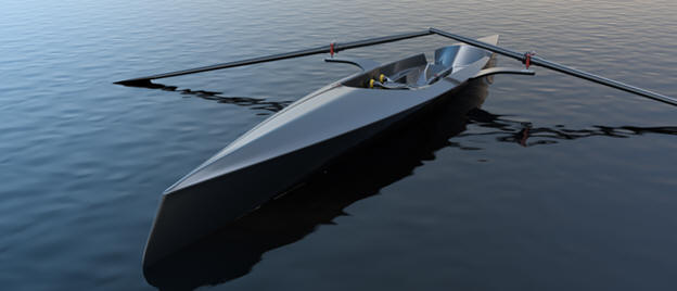
The initial hull design was done in Rhino, which for some reason
is a standard in the boat industry.
The surface already had
a few problems!
It was imported into Fusion 360 and I did
some of the early concept design work, but when it came to surfacing
I hit road blocks every way I tried it.
At this time Phil
was not part of the project, but I suggested to my client that we
needed Phil's help. Phil also hit road blocks in Fusion 360 even
using some of his unique re-topologizing workflows and T-Splines.
The rest is history, as they say.
Thanks to ZW3D
paired with Phil’s surfacing skills we now have tooling for the hull
created.
You should see the images.
Perfectly smooth
reflections!
Peter I saw the
following Inventor YouTube tutorial and thought I would give it a
try on ZW3D. I have to tell you it is almost tortuous to watch
the NX presenter. I
have tried to do top down design in Solidworks and failed. Inventor
is a bit better but all of these programs including Inventor create
external parts. You will see a huge difference in ZW3D's
multi-object design environment.
Inventor is a constrained sketched based
system as are Fusion 360, Solidworks and Creo. In the following
lessons you can see that this modeling paradigm is use throughout
the industry causing millions of wasted hours.
I have never done this type of assembly modeling! ZW3D is designed for top down design!
Not a marginal add-on feature!
I was hired as a Sales/Tech for a company that wanted to provide the
Autodesk Manufacturing Solution that was based on Inventor. So I
started the included self tutorial and found it quite good. As you
watch the presenter create each part separately, the Inventor
tutorial actually introduced you to top down design which was quite
functional, it still save the parts separate from the assembly, but
you could use existing component to create new ones. You can see the
benefits working with ZW3D it truly cuts the design time.
After I learned Inventor I went back to reintroduce myself
to Solidwork to try some top down design. I was incredibly
convoluted and I failed to get the results so easily delivered in
Inventor.
The reference drawings are at the end of the lesson.
Assembly is the very
best feature of ZW3D. With its multi-object design environment it
offers the highest level of productivity. Watch how we use inserting
primitive shapes with a minimum of sketching to complete this job in no
time. Se how easy it is to manipulate parts and an
assemblies in a 3D space.
While creating 3D models from a drawing is the very best
way to learn 3D CAD and maybe some design techniques is does not
expose the designer to the design flexibility necessary in product
design. ZW3D is all top down due to the Multi-Object environment.
Creating mating parts is a cruise. But modeling is just one aspect of a
well designed productive 3D CAD system. ZW3D vs Inventor
ZW3D is very similar to
Inventor and the Pro/e
clones with differences that make it much more streamlined. It is very easy for those users
to get up and running with ZW3D. The unique benefits over the other systems
is the multi-object environment with the integrated drawing. You can
do complete projects (parts, assemblies and drawings) in one file.
I would do a
video, but I really am not good at it. So I will show you step by
step. I will try and get ZW3D support to create one. They are
very good.
ZW3D is a history/sketched based
system with planes, but it also has primitive shapes to increase
your productivity. It seems to me watching this Inventor
exercises that there is no concern for simplifying the process and
increase design productivity. Most of us do engineering design and
have schedules to meet. Not only do these more productive modeling
techniques and a productive system increase design speed it allows
us to meet our goals much easier. Especially with changes.
I
have to say this is incredibly simple. But the Inventor presenter has been
indoctrinated into these designs time consuming modeling techniques. The Solidworks clones are costing the industry millions, if not billions,
in lost productivity.
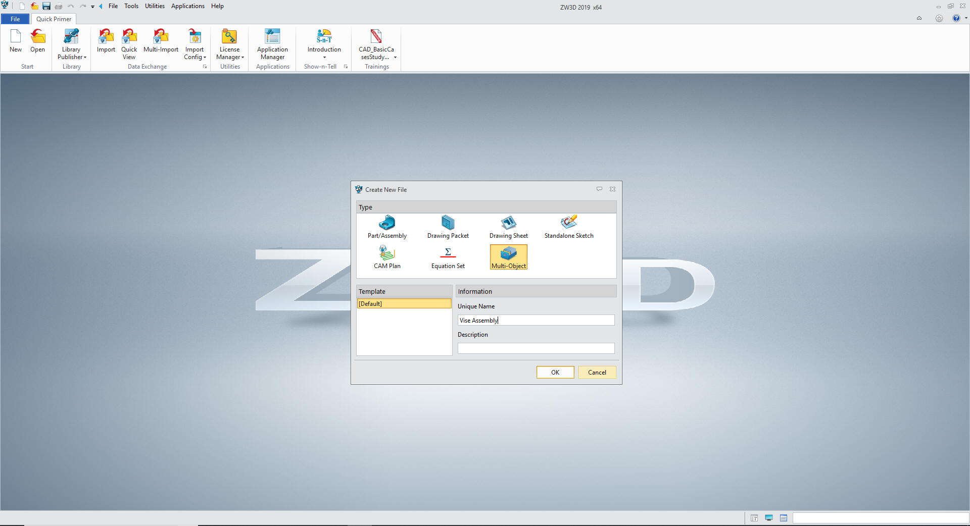
Here is ZW3D. It is set to inches so let's
get started
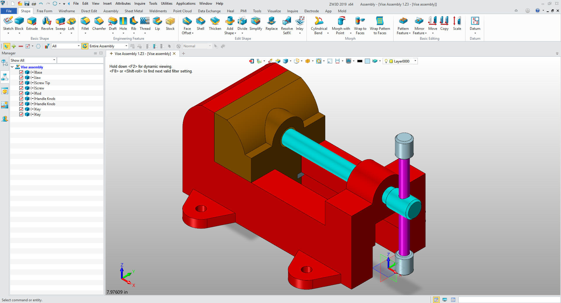
We have to set ZW3D for an assembly. We open a
multi-object file and call it Vise Assembly.
These have actually turned into exercises in
modeling techniques as compared to showing a more productive CAD
systems. Again, I say there are many different ways to model a part.
I see with my exposure to direct edit modelers like CADKEY, I
rarely sketch like you see the Inventor fellow doing. I have always
created my basic sketches by mostly creating offsets and trimming or
extending. It seems to be much easier. I never put in a fillet that
can be created later. What do you think?
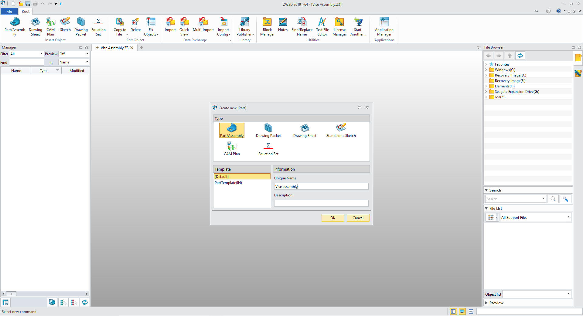
I will insert
my first component which will be the top assembly and call it also
the Vise Assembly
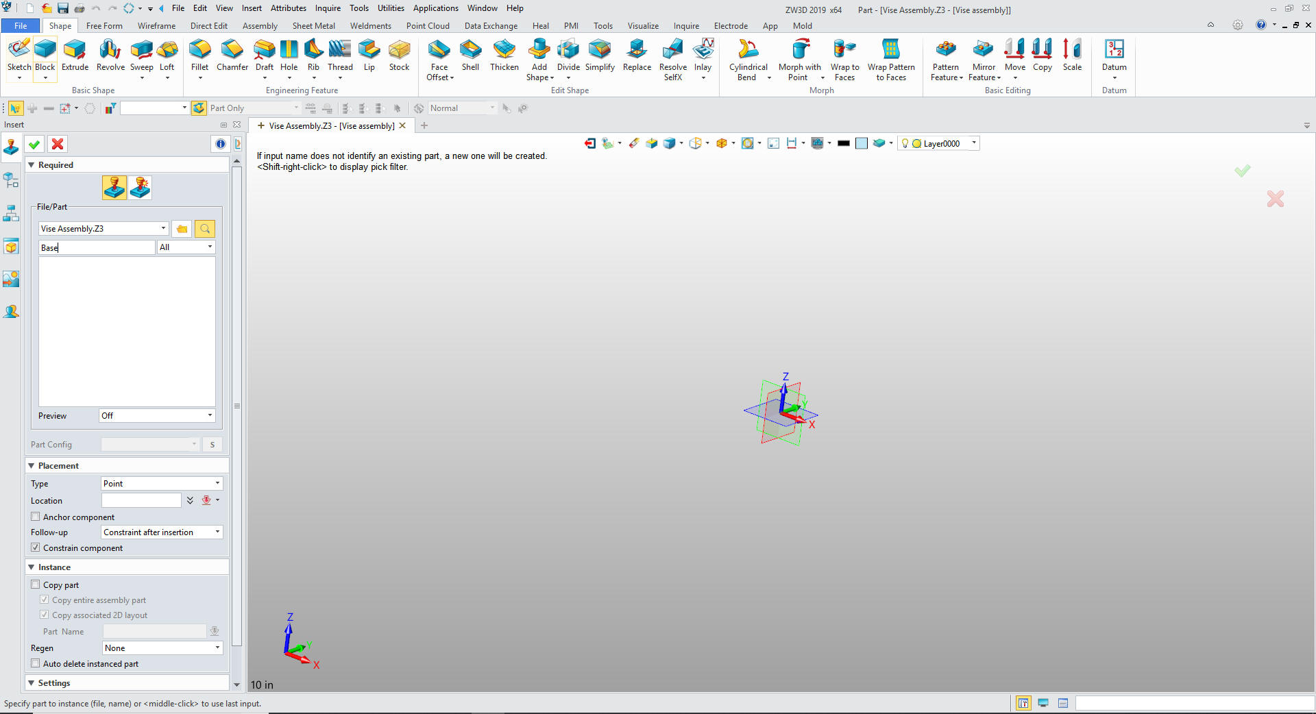
We insert a
component under Vise Assembly and call it Base
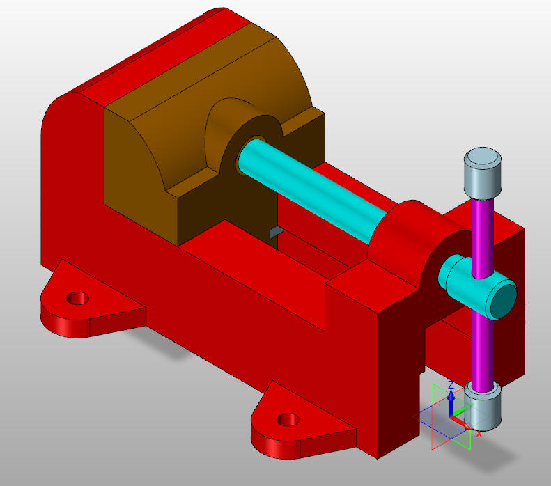
We have to
review the part and think about how were are going to model it. We
can start anywhere but if we pay attention it will be much easier to
model. These drawing to model exercises extend into our design
practices.
I design with Feature Based Design, while working
with primitive shapes makes this process obvious you can also do it
with sketches. You review the part and see the basics shapes not
jumping to an obvious yet overly complex constrained sketch.
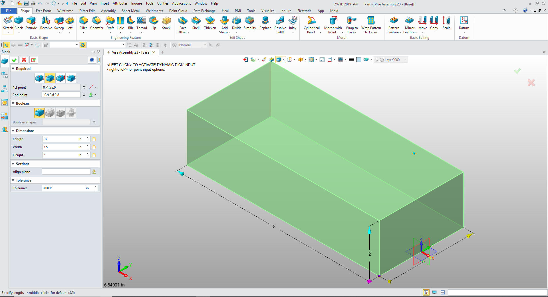
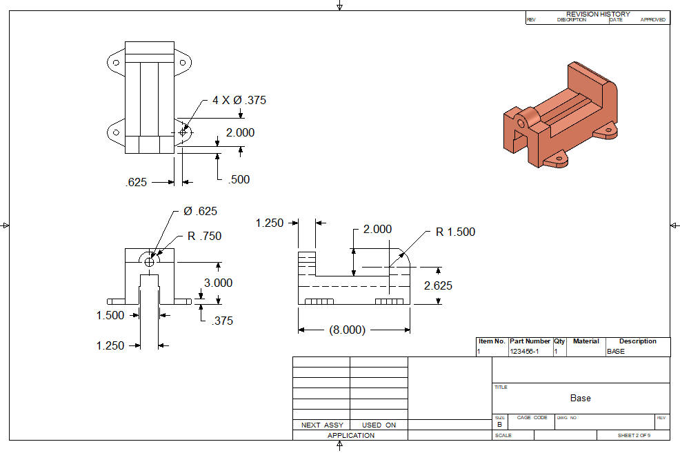
We insert a
primitive corner block. I locate the origin of the block offset
-1.75 Y from X0Y0Z0 and size it.
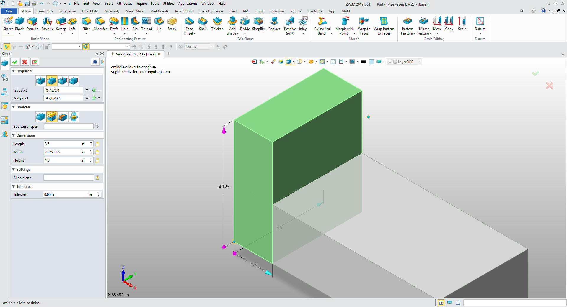
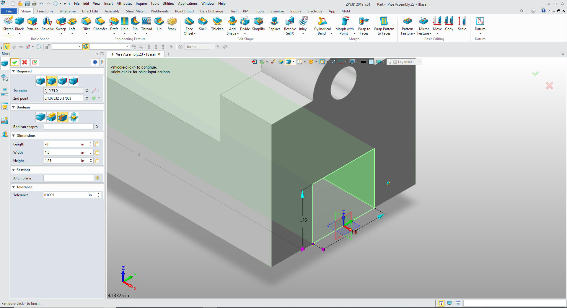
We insert another primitive
center block using the lower left corner of the existing block and
set it to add. We will set the height to 2.625+1.5 so we can put in
the fillet.
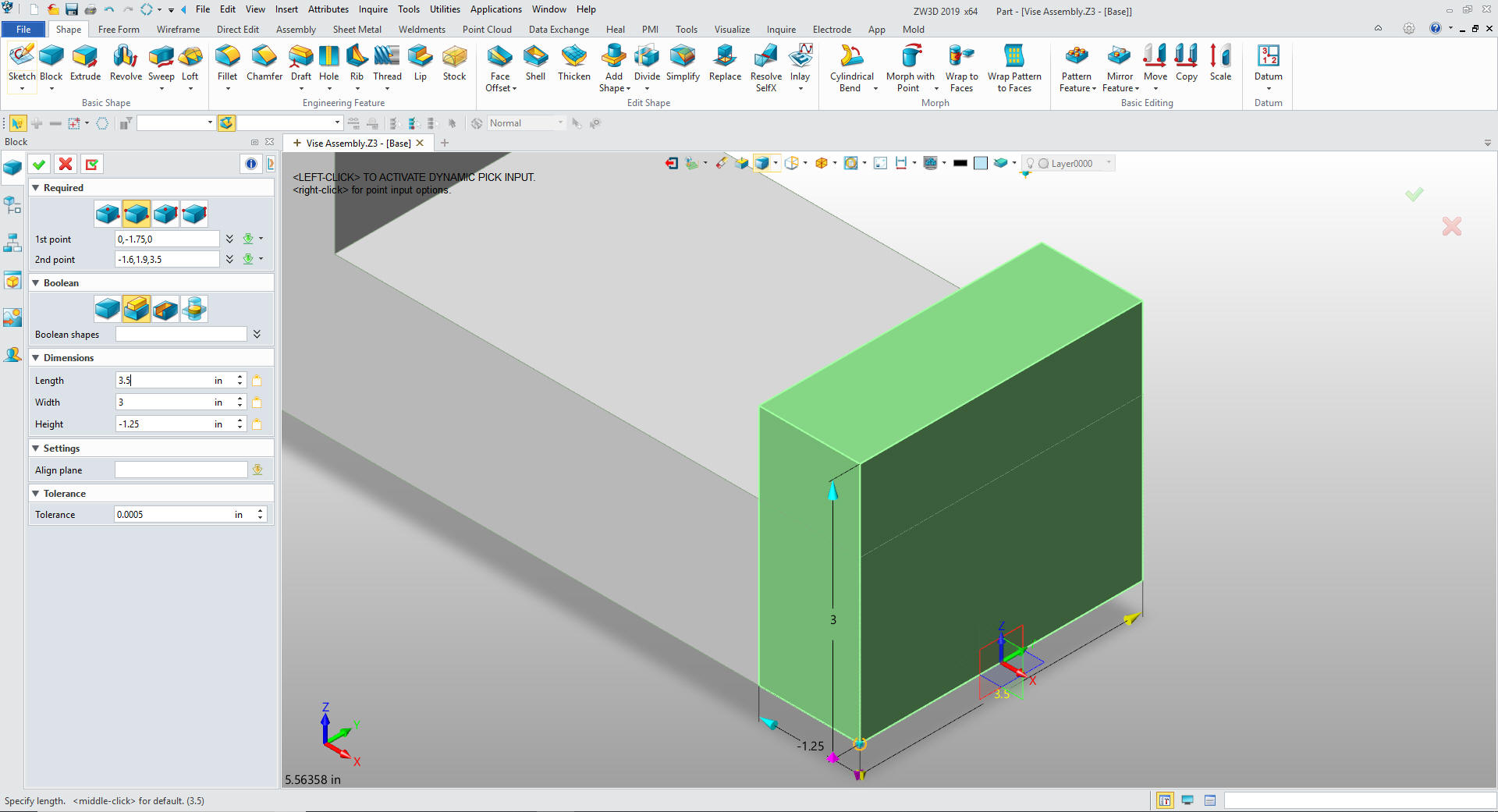
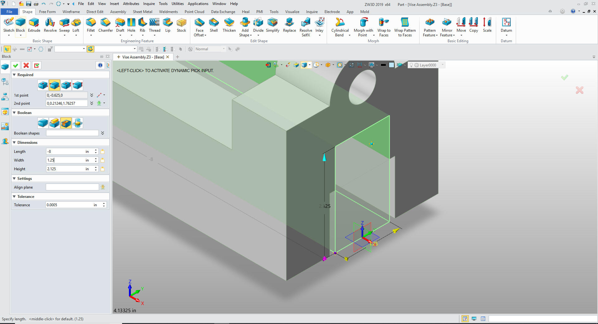
We add the front block the same as the
first and size it.
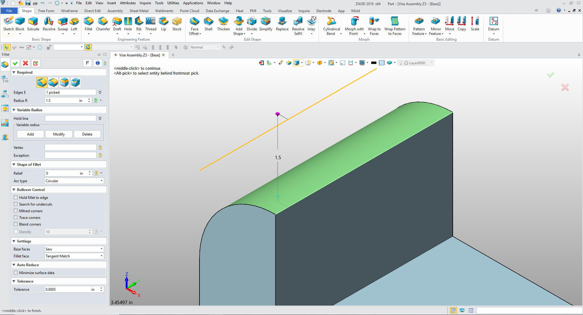
We create the fillet.
We insert a
primitive block on the corner of the fillet set to remove and size
it. Nothing can be easier.
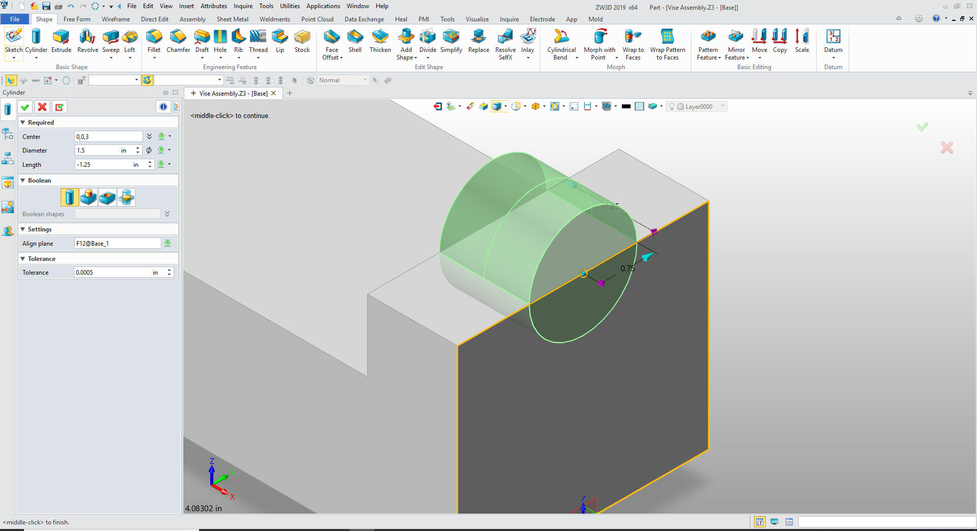
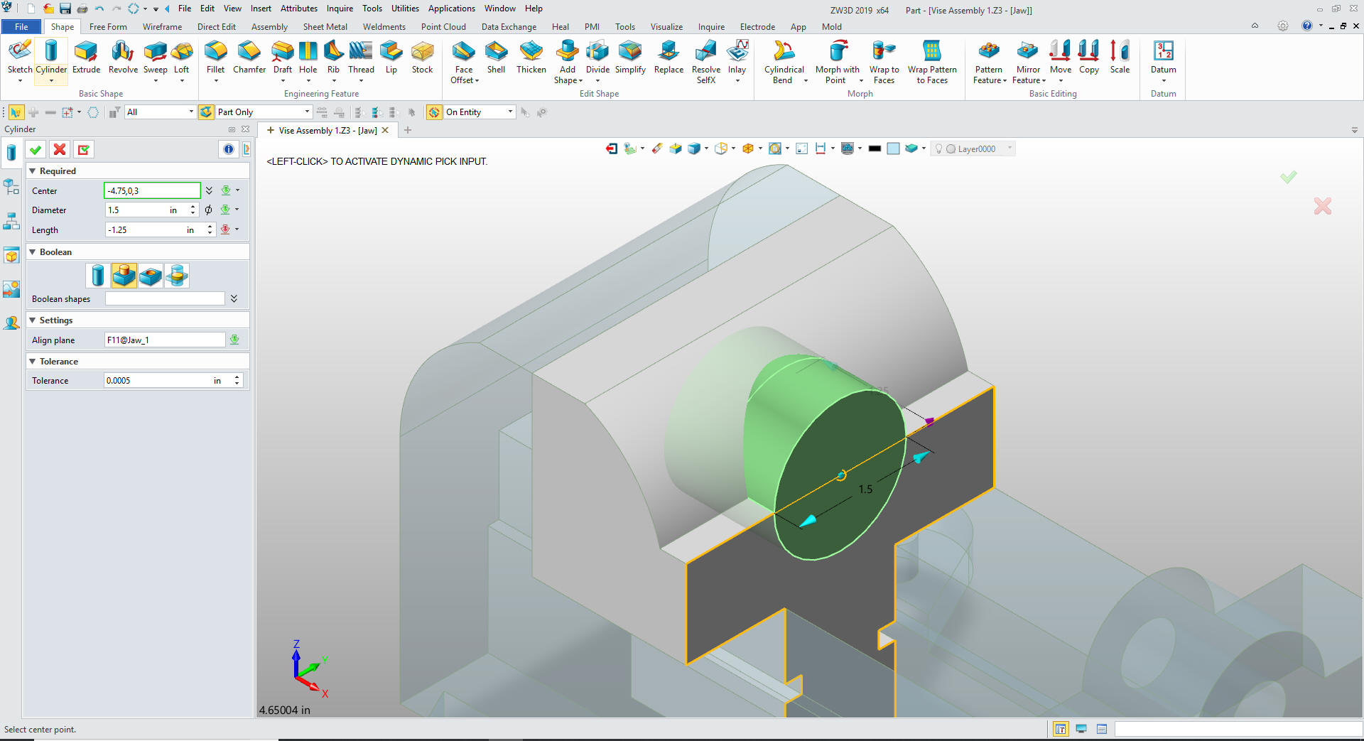
We insert a
cylinder on the top edge of the front face set it to add and size
it.
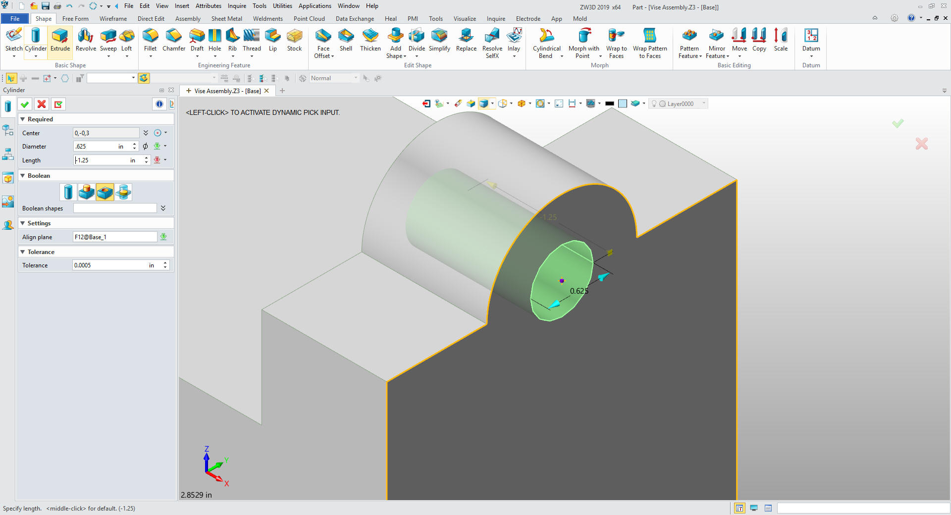
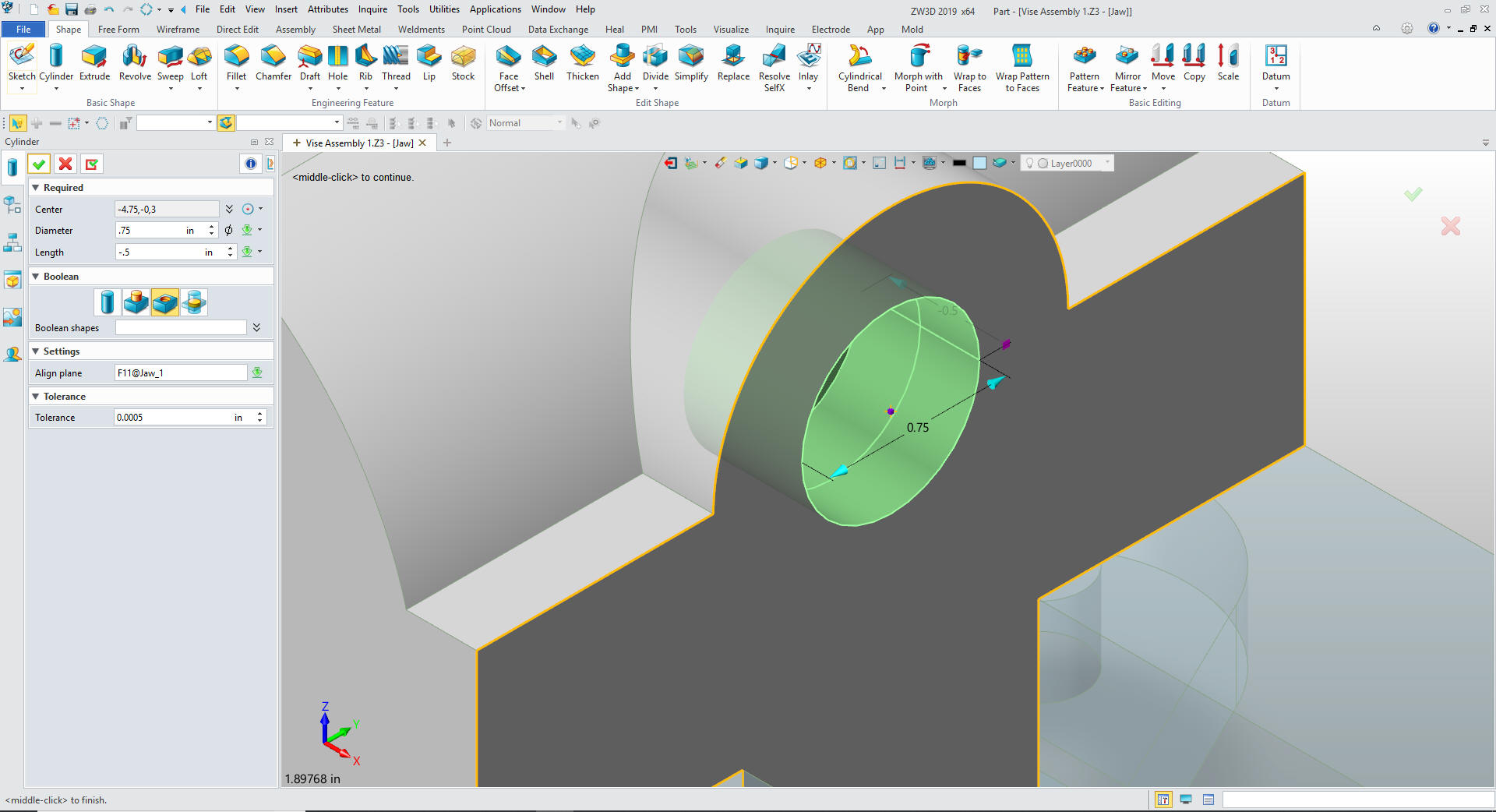
We insert a cylinder at the center of the
boss, set it to remove, size it and set to remove.
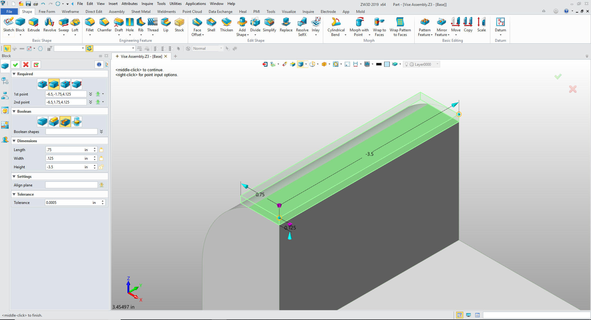
We
insert a center block and offset the 1st point of the block .75
along Y from X0Y0Z0. As you can see how we locate the part
originally aids in the ease of modeling. We just size it and set it
to remove and we are done.
We do the inner block the same way.
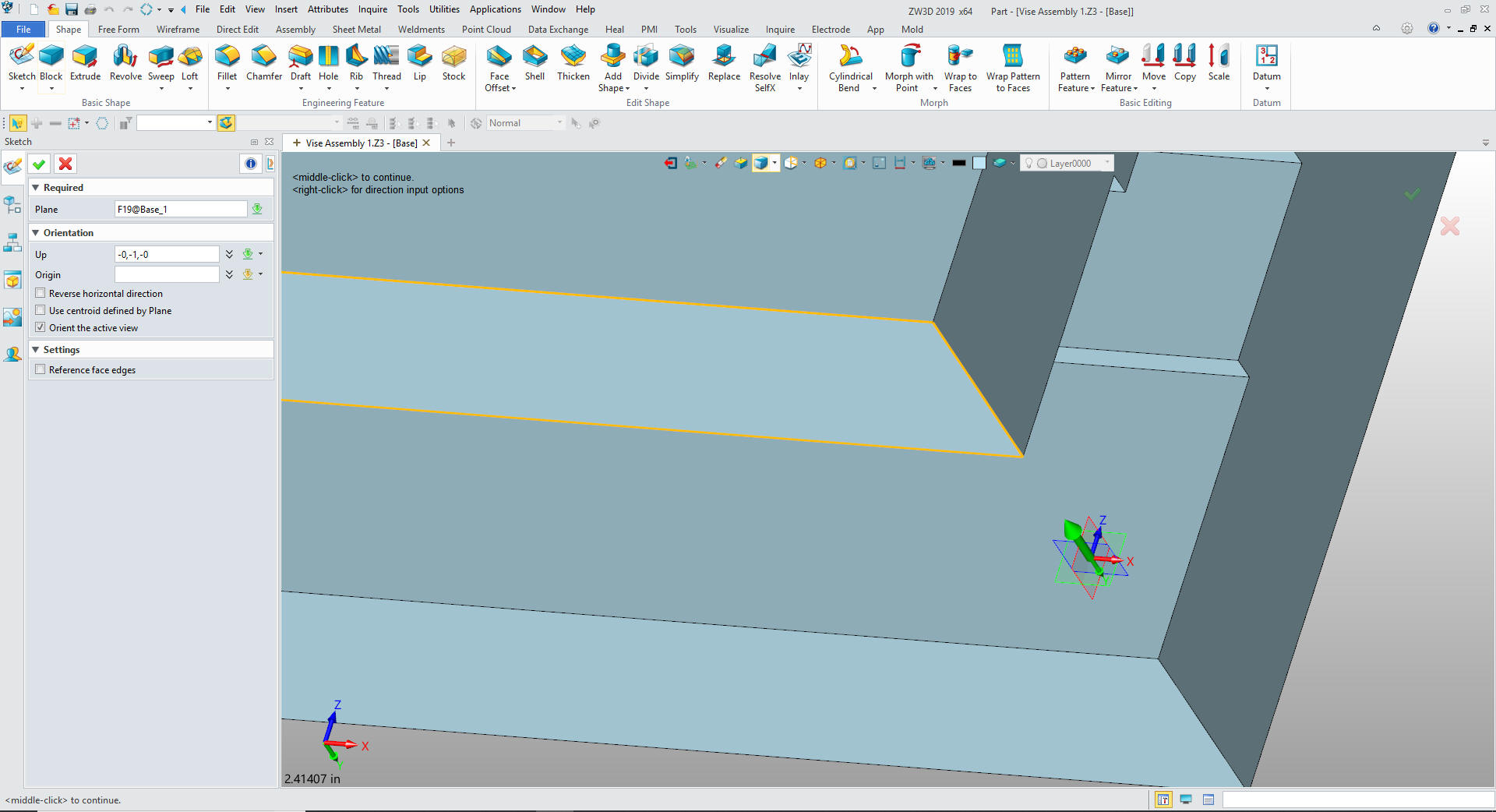
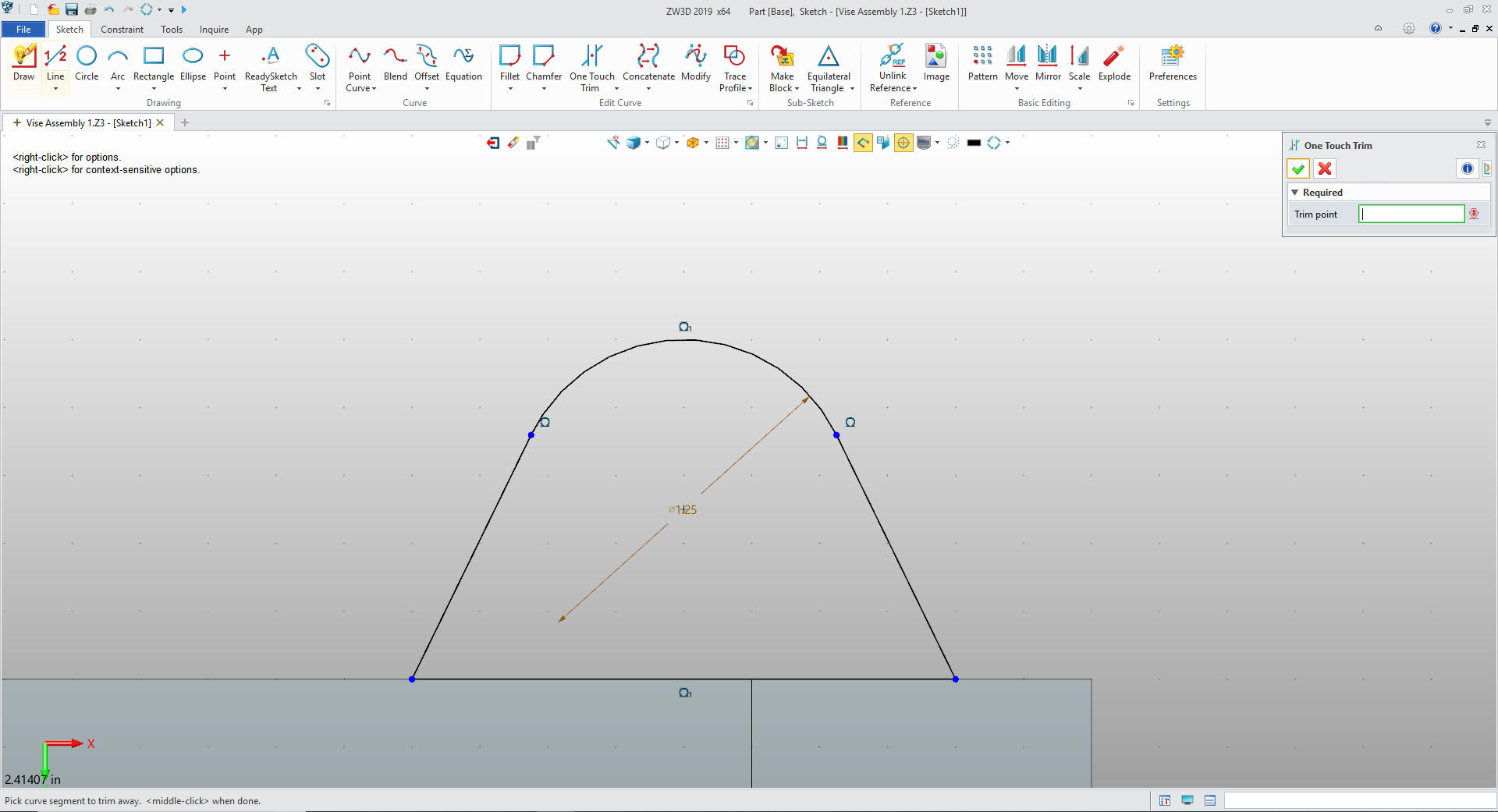
Now for the feet. We create a sketch on
the bottom of the base.
I use
StreamLined Sketching so the first thing I do is create a horizontal
.5 line to set the point for the base of my foot. I then create the
base horizontal 2.0 inch line, I create a .625 vertical line from
the mid-point of the 2.0 inch line. I create a boundry circle at the
ends of the .625 line. I create tangent lines from the circle to the
ends of the 2.0 inch lines. No constraints. Much faster.
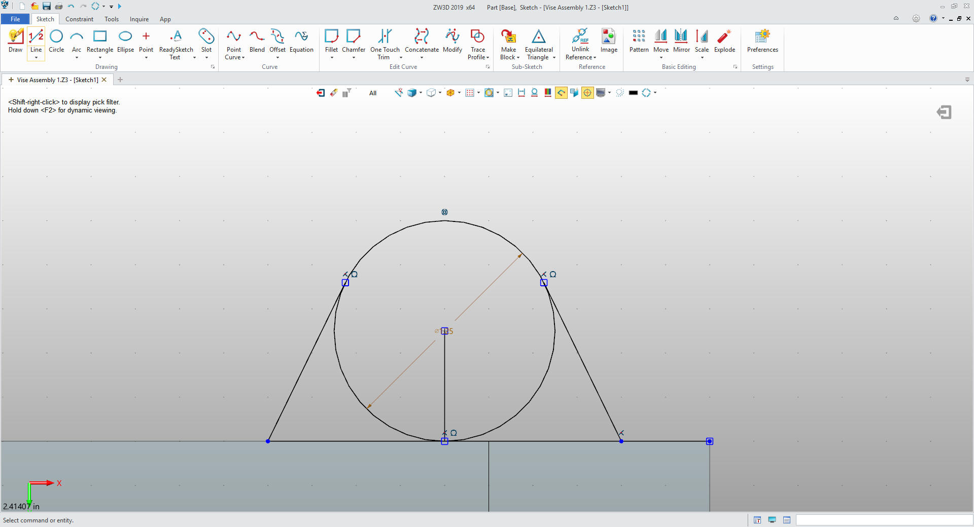
We trim as required and we are done with
the sketch. If you watch the Inventor presenter he makes this so
complicated by drawing to full feet. If I wanted to create two feet
in the sketch I would just mirror the first sketch. I will just have
on sketch and pattern it so I can always just edit one of the
sketches.
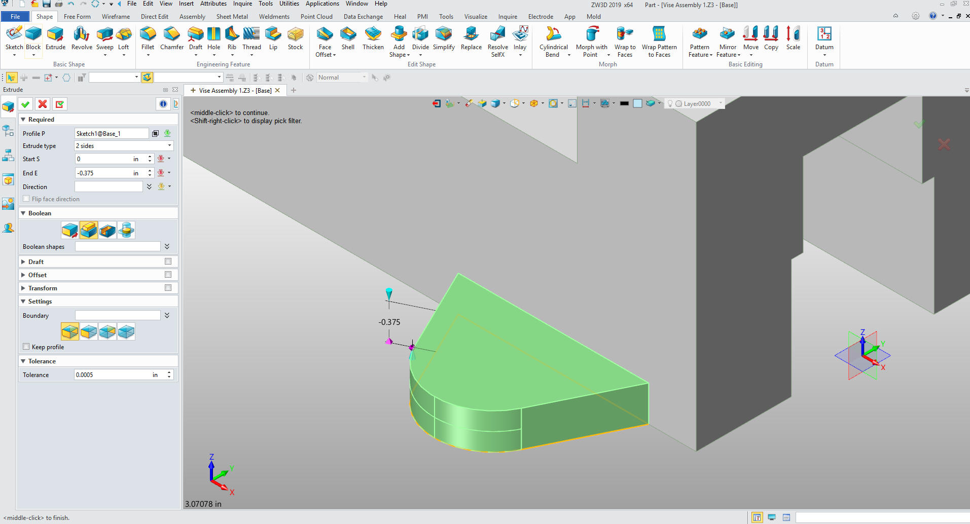
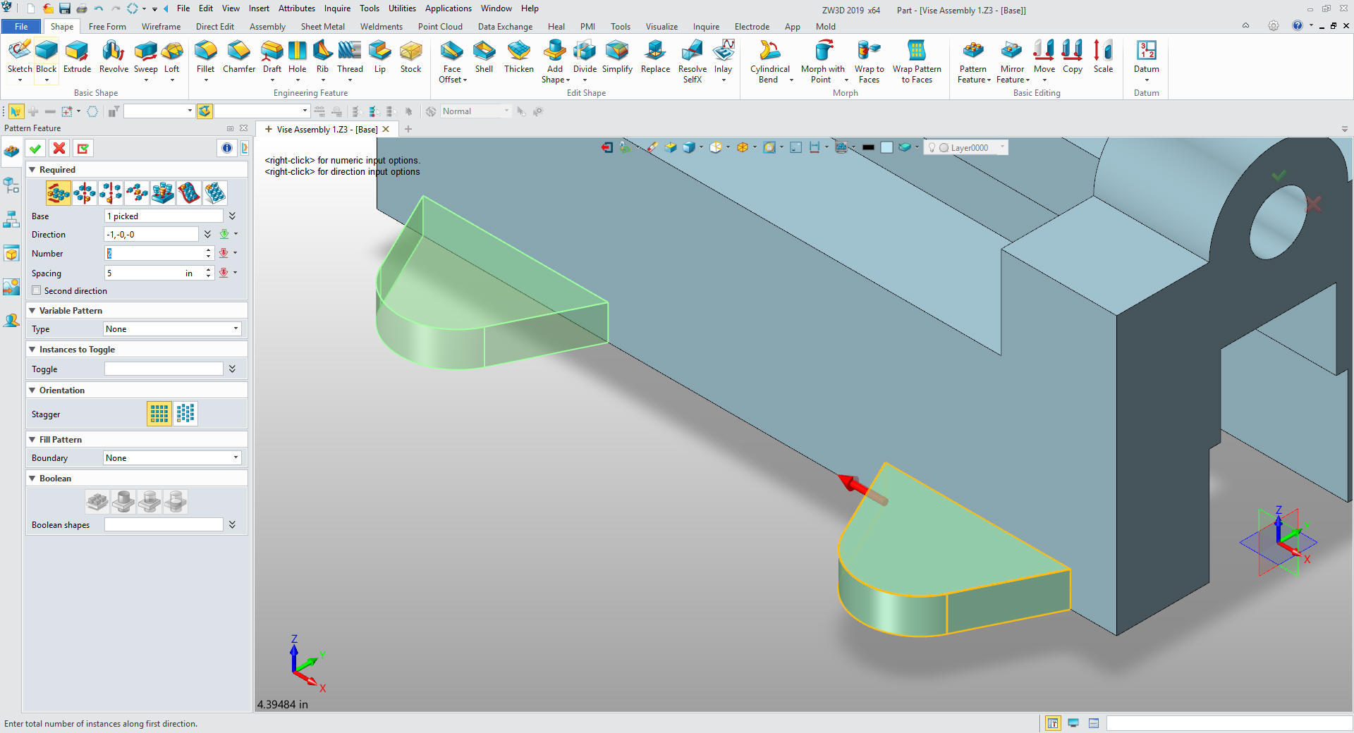
We extrude the sketch and set to add
We
just pattern the foot. So simple.
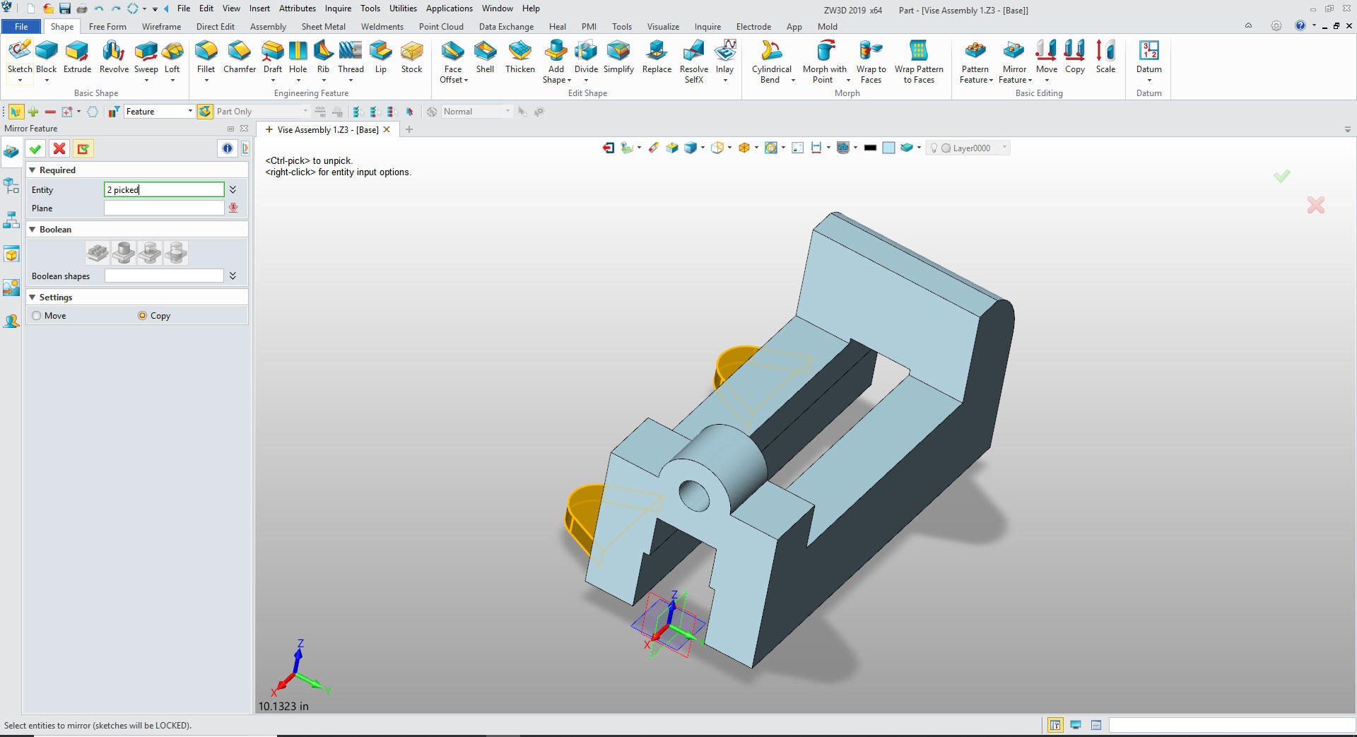
Now of the the other side. Just mirror the
feet by the XZ plane. Again we are reminded how setting the origin
in the beginning makes designing easier.
Select okay and we are done.
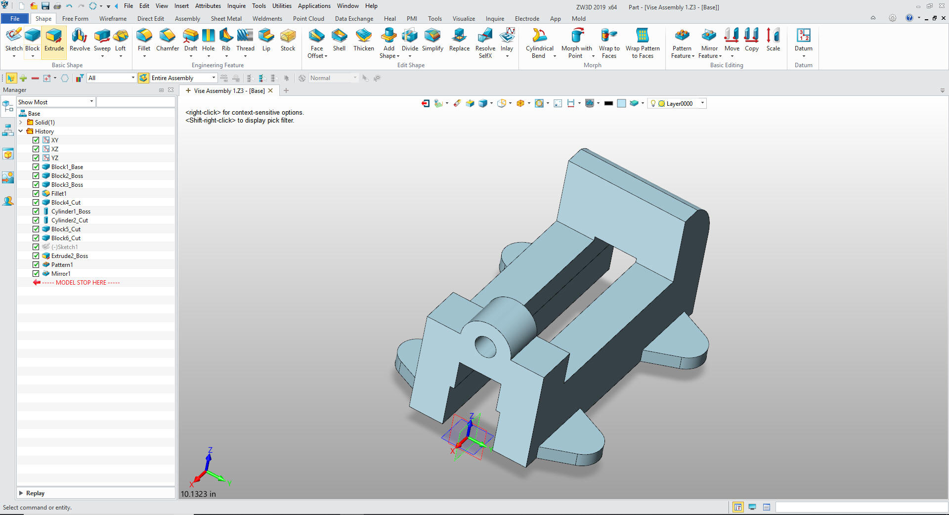
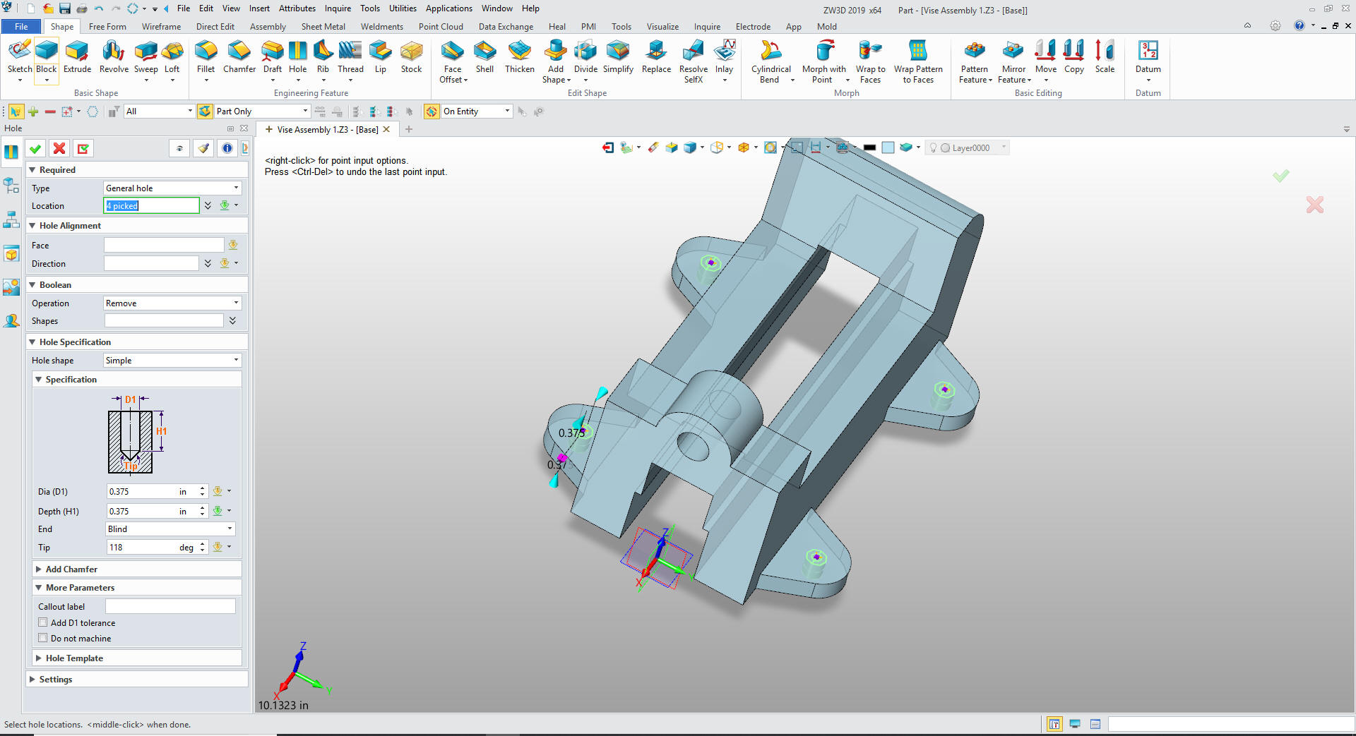
Now for the holes. It is a bit weird the
the Inventor presenter has to create points to locate the hole. I
Found this true about the Catia presentation also. ZW3D recognizes
centers of the radii of the feet so we can skip that step.
We set the size of the hole and select the centers.
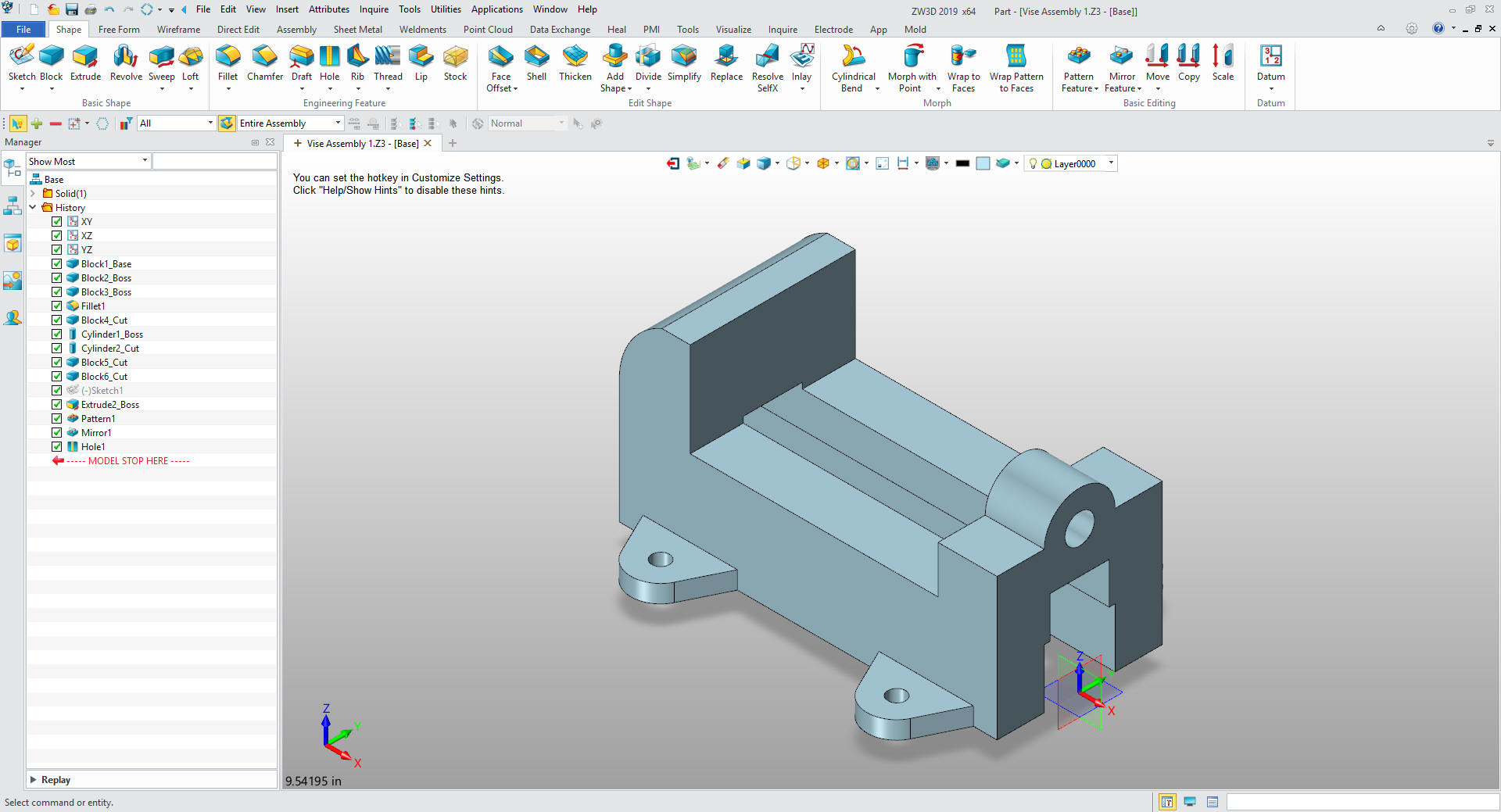
We select Okay and
we are done with the Base.
ZW3D was designed from the ground up
for top down or in context design and has many functions that make it
much easier. You can see the time saved not only in much more
productive modeling but having the mating parts available for
reference.
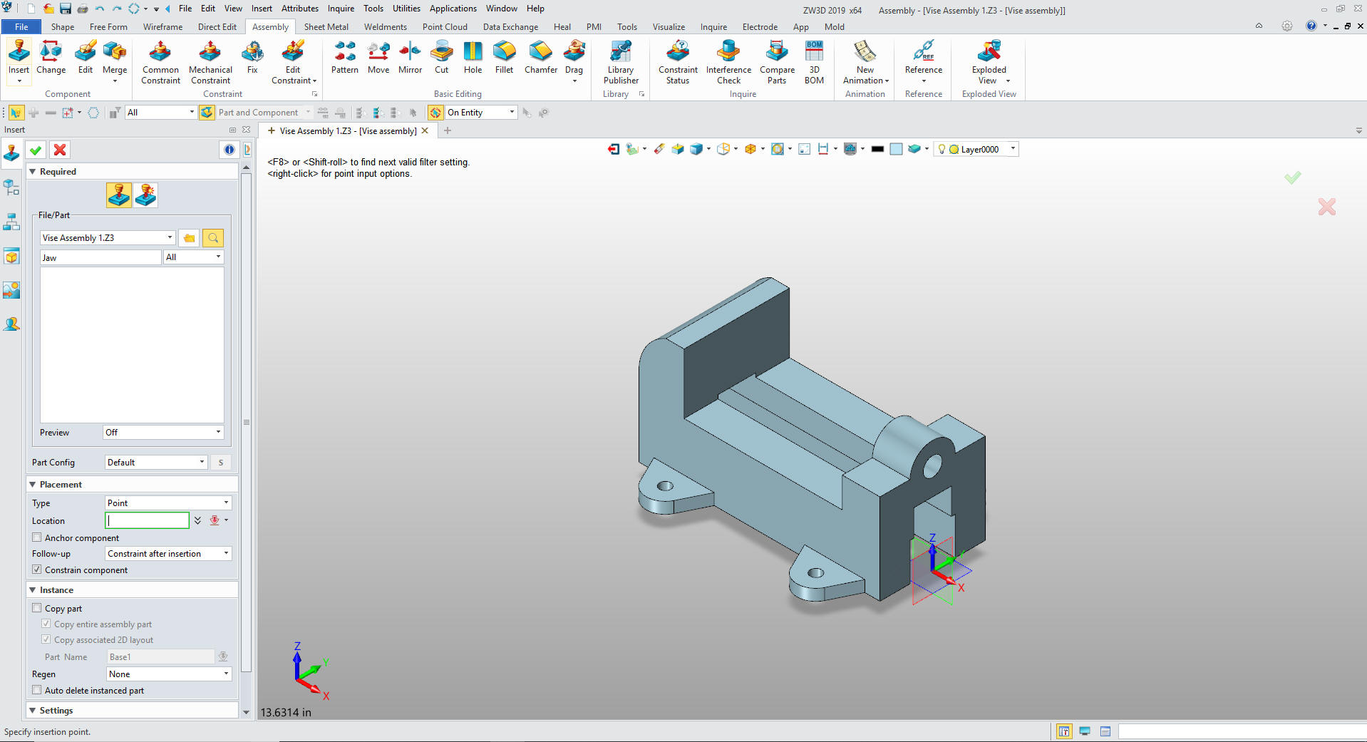
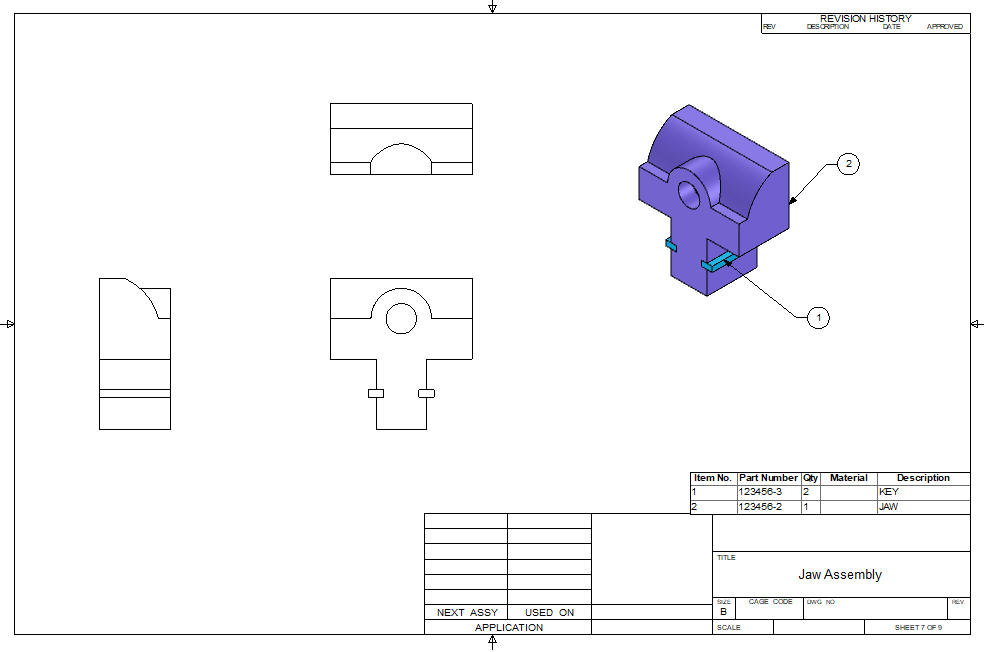
We insert a new component under Vise
Assembly and call it Jaw.
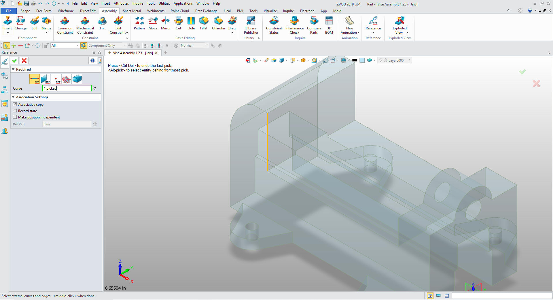
We go to the assembly mode and create a
reference entity of the vertical inside edge to create a point to
put in our basic block. This is the beginning of our top down and in
context design process.
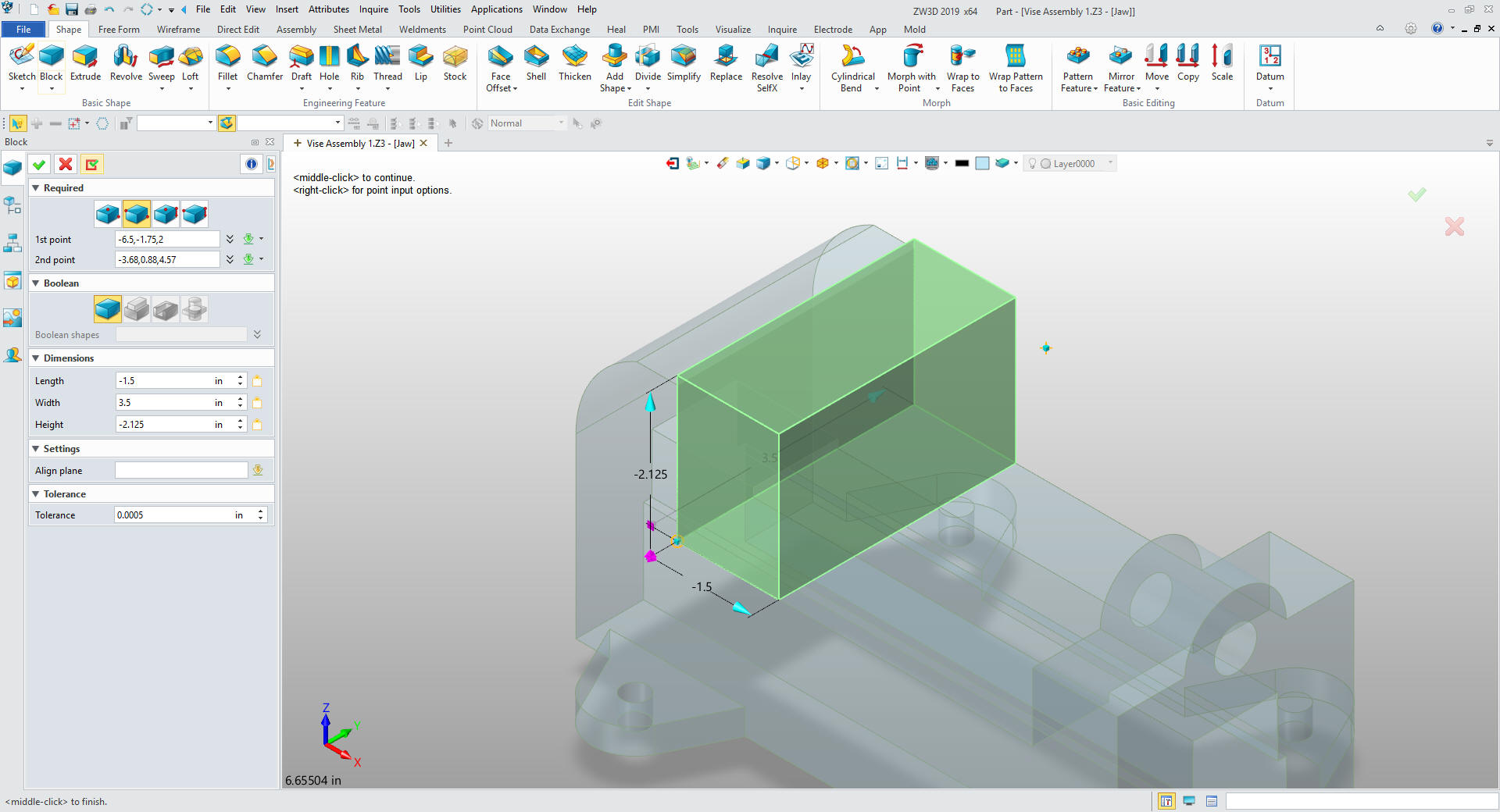
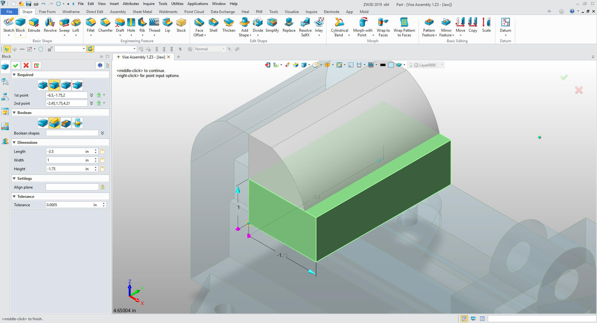
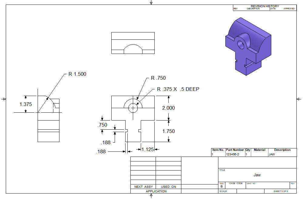
We insert a corner primitive
block using the bottom end of the line we just created and size the
block adding the .125 so we can create the fillet. Since this is a
new part it is automatically set to base.
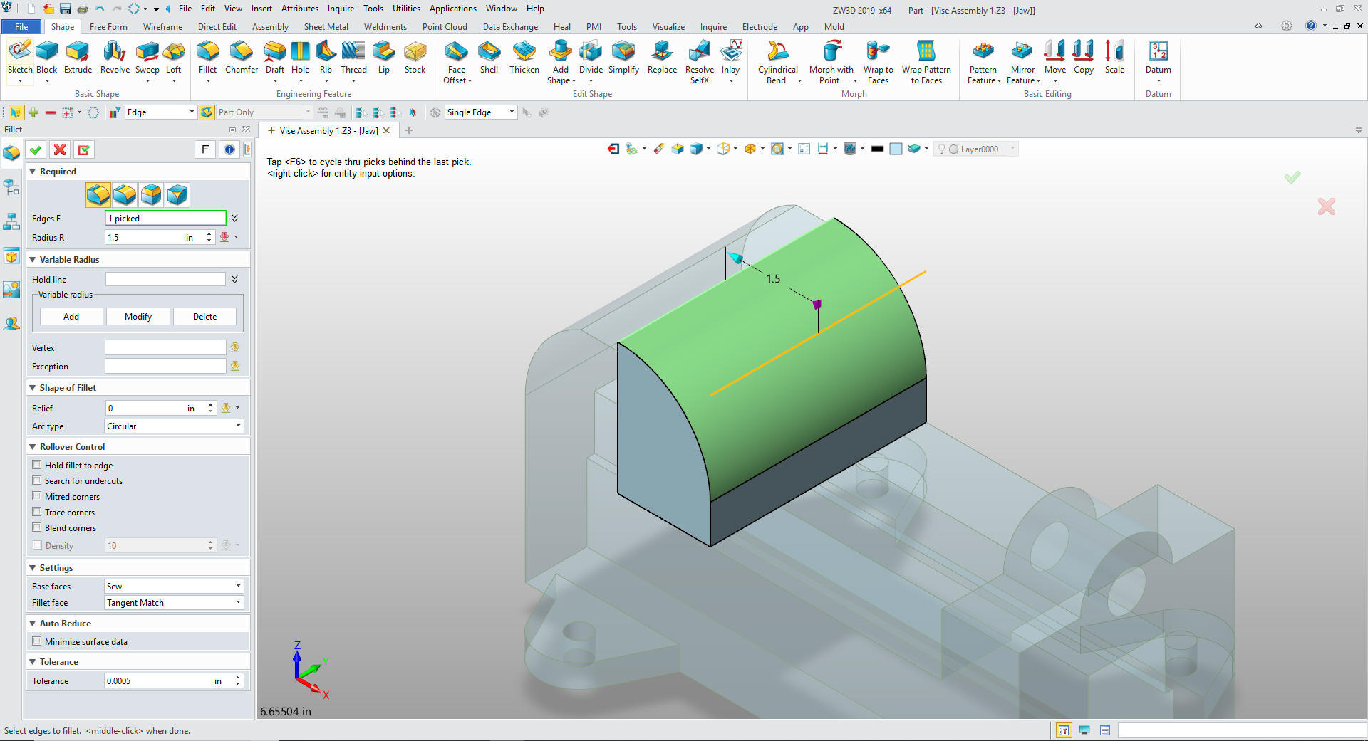
We
add the fillet.
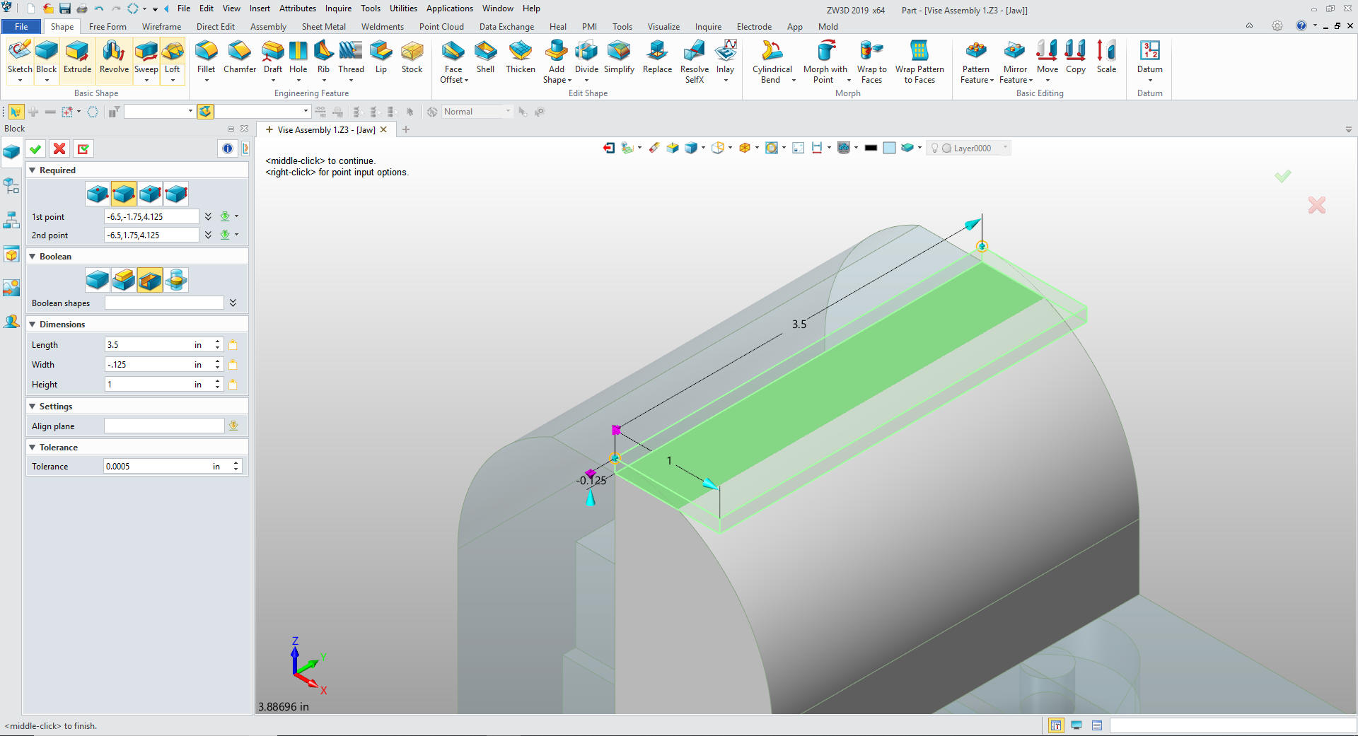
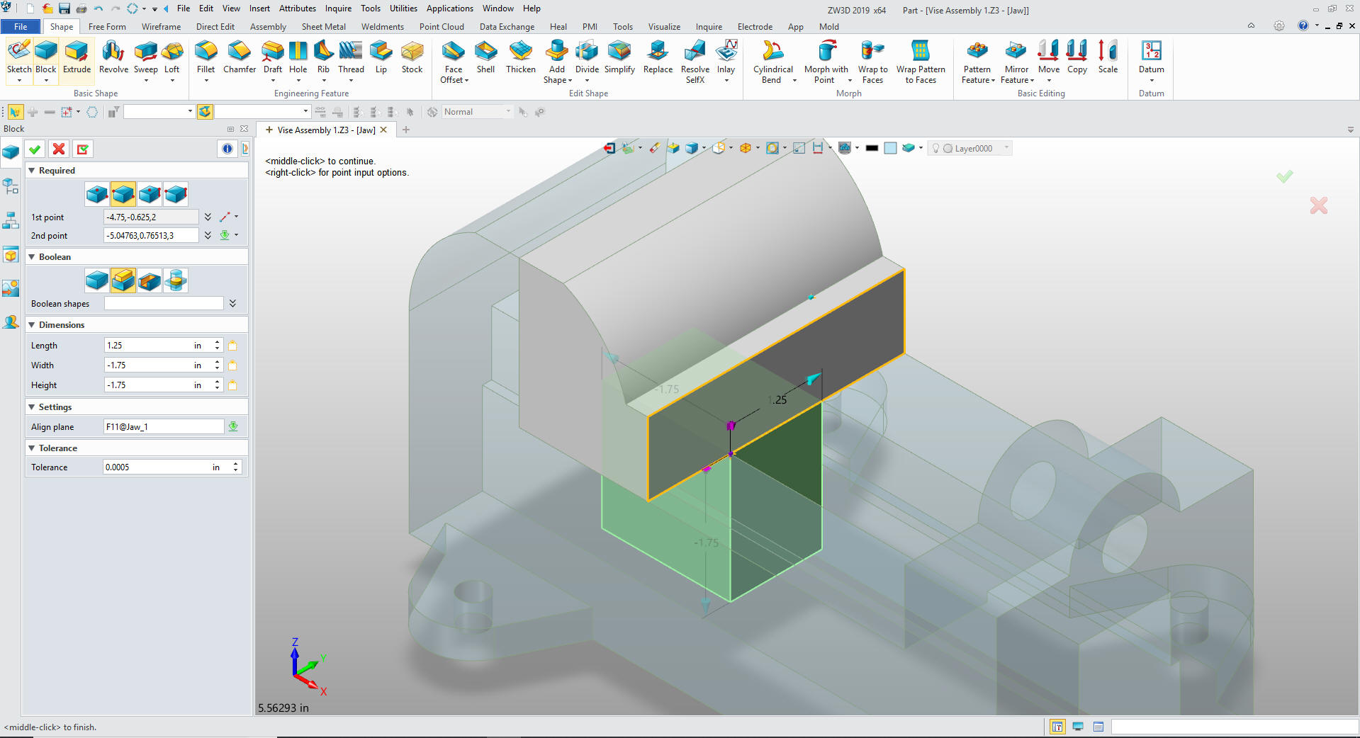
We
insert a corner primitive block on the top corner of the fillet and
size it and set to remover. So, so easy.
We
insert another corner primitive block at the bottom left corner of
the shape and size it and set to add. It's so easy!!
I
insert another corner primitive block and locate it by offsetting
.625 from the mid-point of the bottom edge of the shape, sizing it
and setting to add.
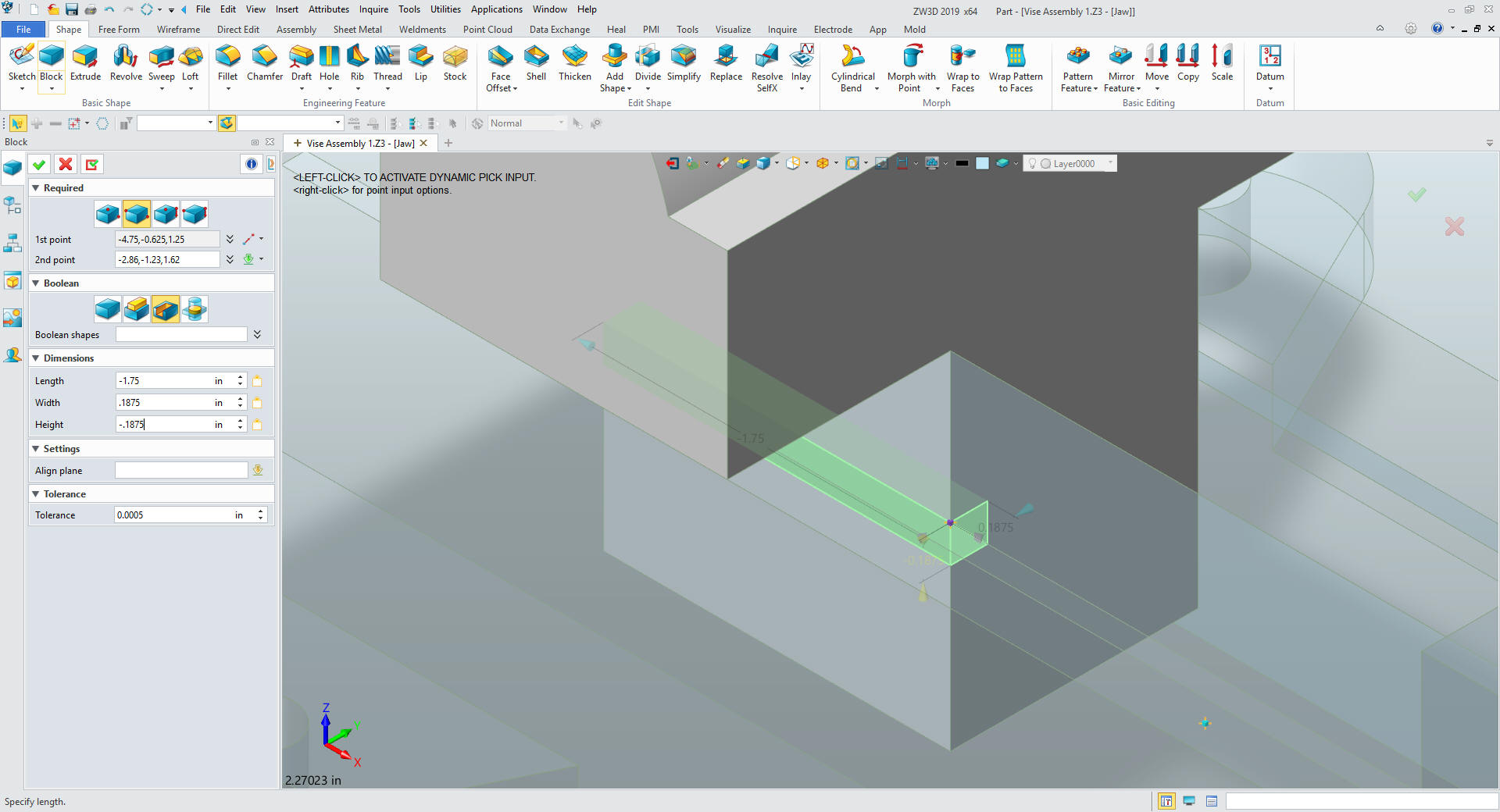
We
insert a corner primitive block by offsetting .75 at corner of the
lower left side of the bottom feature, size it and set to remove.
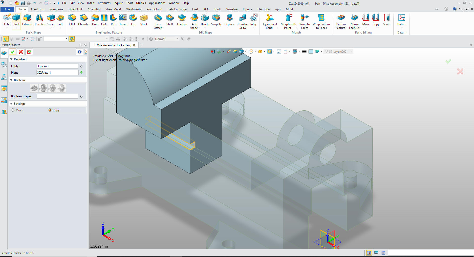
We
mirror the feature across the XZ plane.
We select okay. We insert a primitive cylinder on the front face
of the Jaw and at the mid-point of the related edge, size it and set
to add.
We
insert another primitive cylinder in the center of the boss, size it
and set to remove.
We are
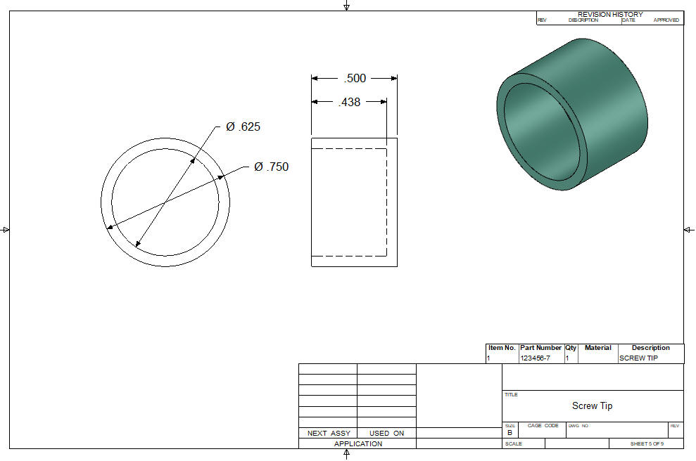
done with the Jaw. We will change the colors and insert the new
component. We will create a Screw Tip since we could not get the
screw through the hole. This part is just to modeling practice, but
we should make it bit more real.
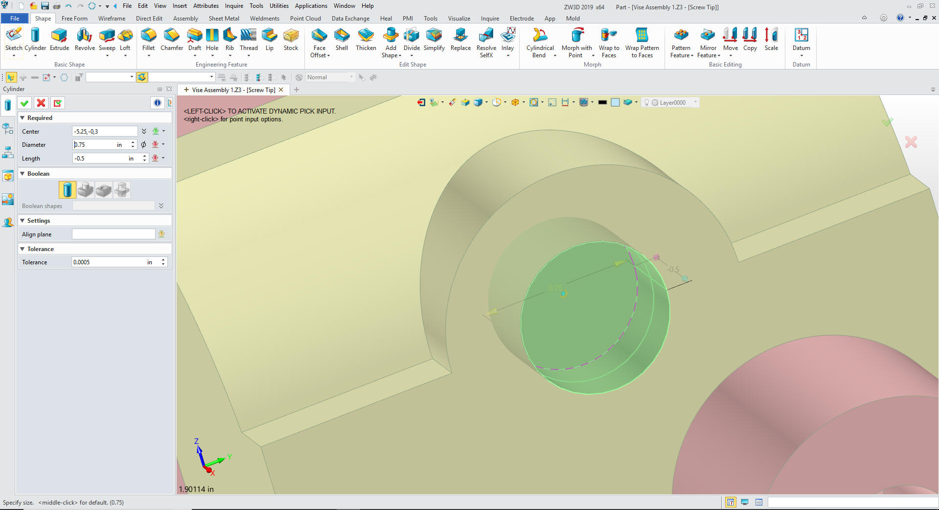
We will go the assembly
mode and create a reference entity on the back circle. We will
insert a cylinder using the center of the reference circle, size it
and it is automatically set to base.
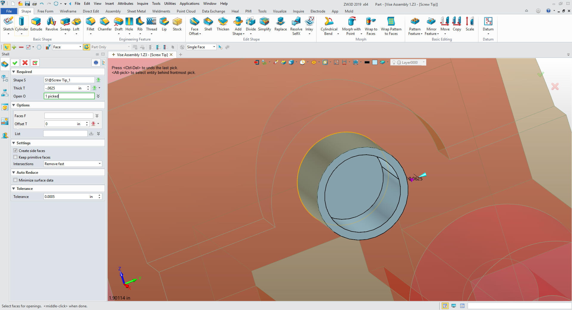
We need to shell that shape. This is the only step we need to do
with the part. You can see we design much differently with what I
have coined Feature Based modeling.
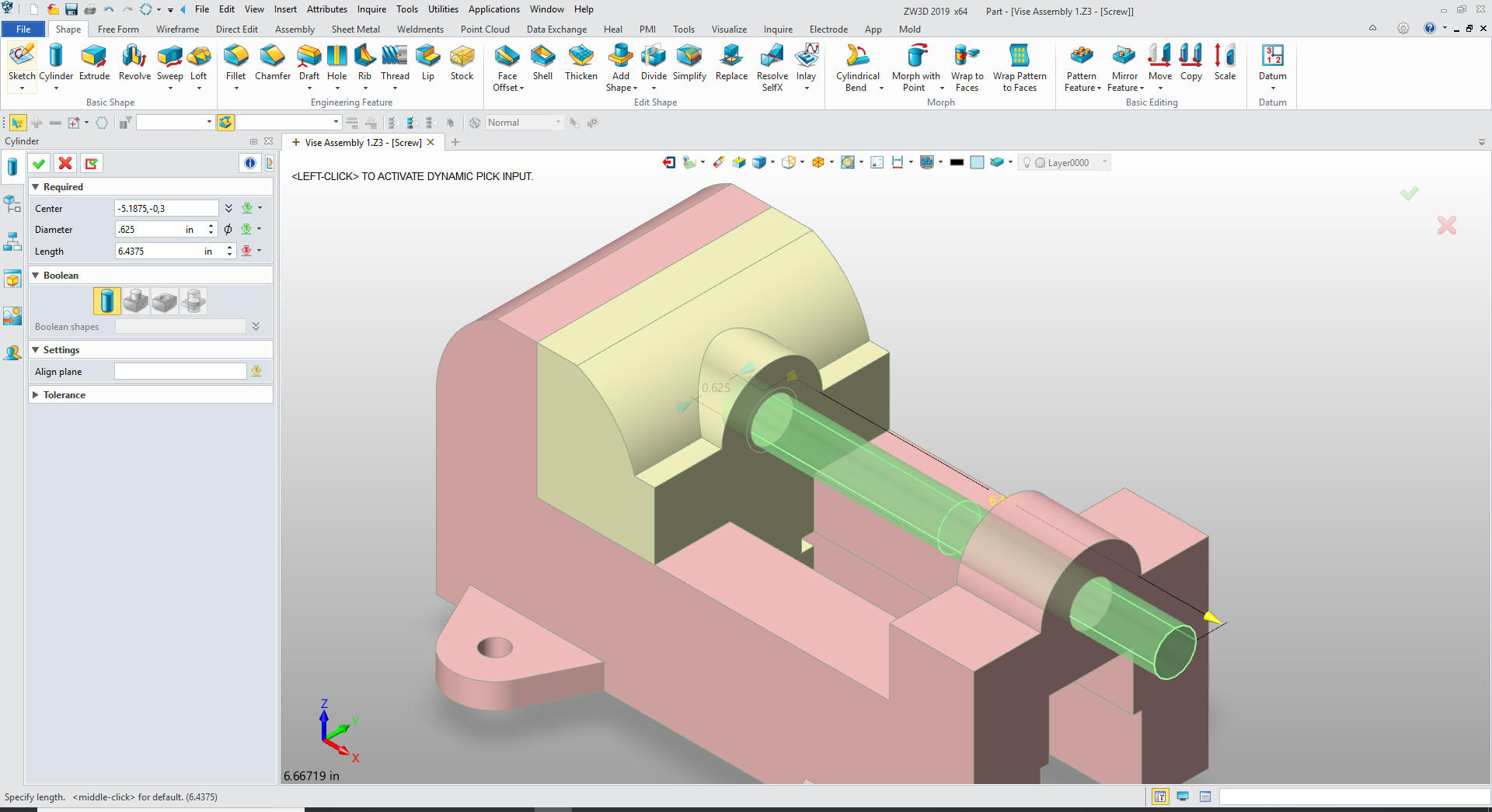
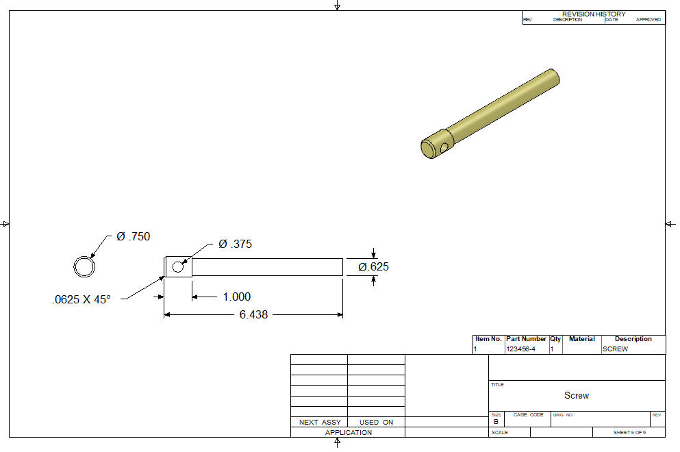
We
change the color of the Screw Tip. We insert a component and call it
screw. Again we go to the assembly mode and create a reference
entity of the back circle in the Screw Tip. We insert a cylinder
primitive at the center and size it again it is automatically set to
base since it is a new component.
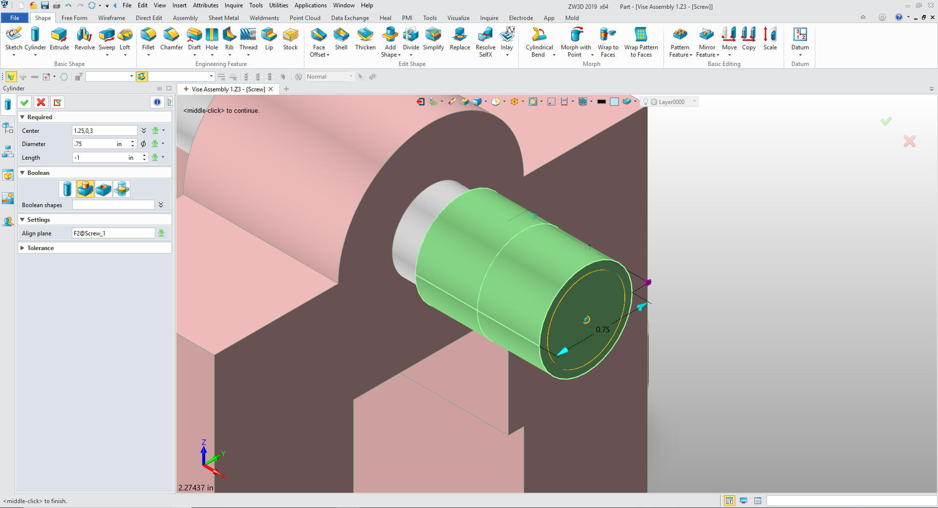
We
insert a cylinder primitive at the end of the rod, size it and set
to add.
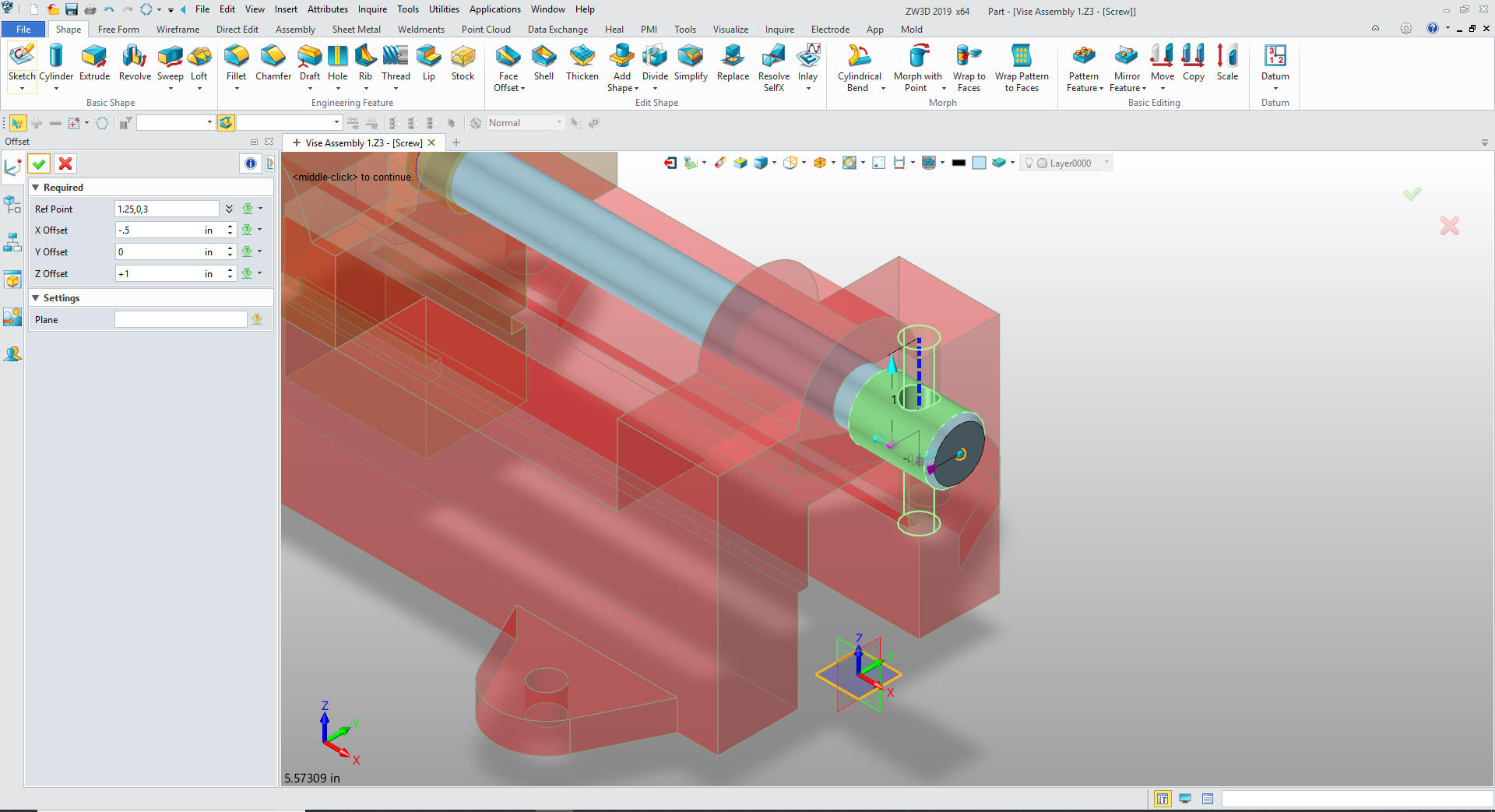
We
create the chamfer and create the hole. We set the XY plane then use
offset setting -.5 in the X and 1.0 in the Z.
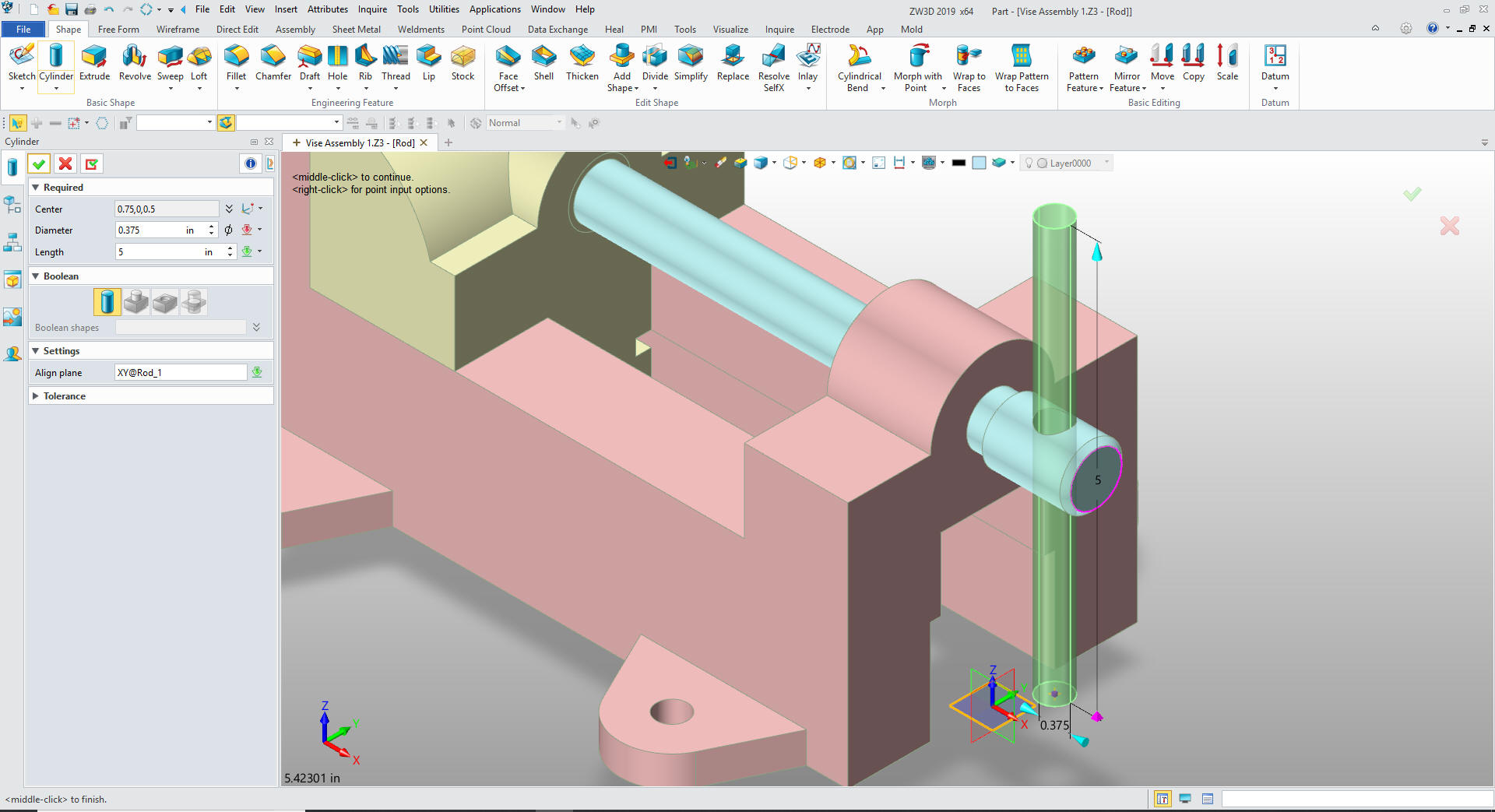
We
create a new component the Handle Rod. We have to first go to the
assembly mode and create a reference entity from the front edge of
the Screw. We then insert a cylinder primitive and select the XY
plane for alignment. We select offset and select the center of the
reference circle. We set X -.5 and Z -2.5.
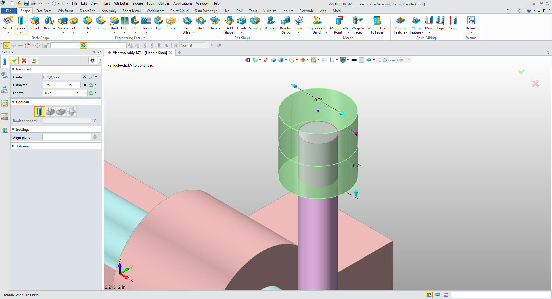
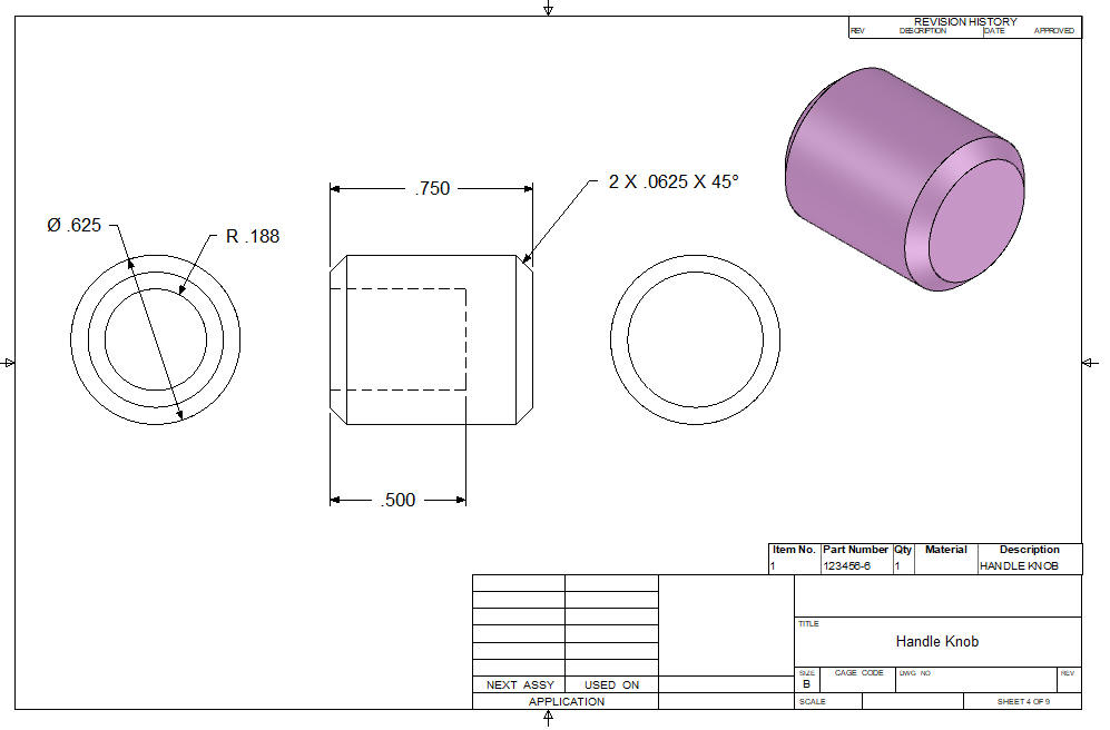
We
select okay we are done with the rod. We add a new component called
Handle Knob. We go to the assembly mode and create a reference
entity from the top of the rod. We insert a cylinder primitive using
the center of the reference circle and use offset distance from that
enter setting the distance to point .25.
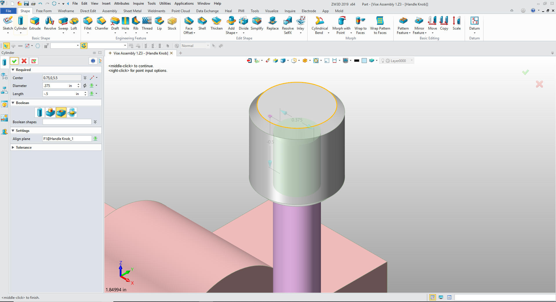
We add
the chamfers. Then we insert a cylinder using the center of the
knob. We use edit distance option of .25, set the size and set to
remove.
We
insert another knob. I will allow it to stay in the same location. I
select the assembly mode and rotate it 180 and we are done with the
Vise Assembly.
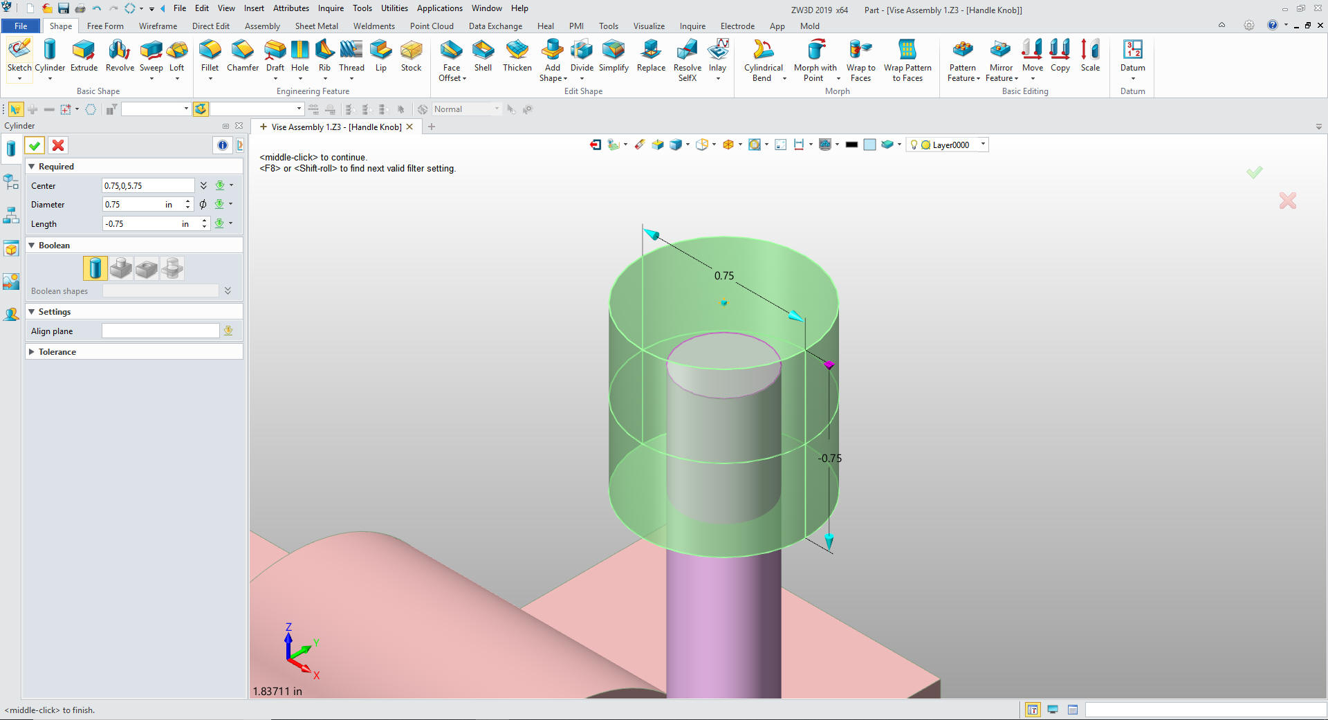
Hmm Wait a minute the knob looks too big. I
select the Handle Knob and edit. I select the base cylinder and see
it is .75. I change it to .625. How simple was that. Both Knob are
updated and now we are done with the Vise Assembly.
Oh Oh.
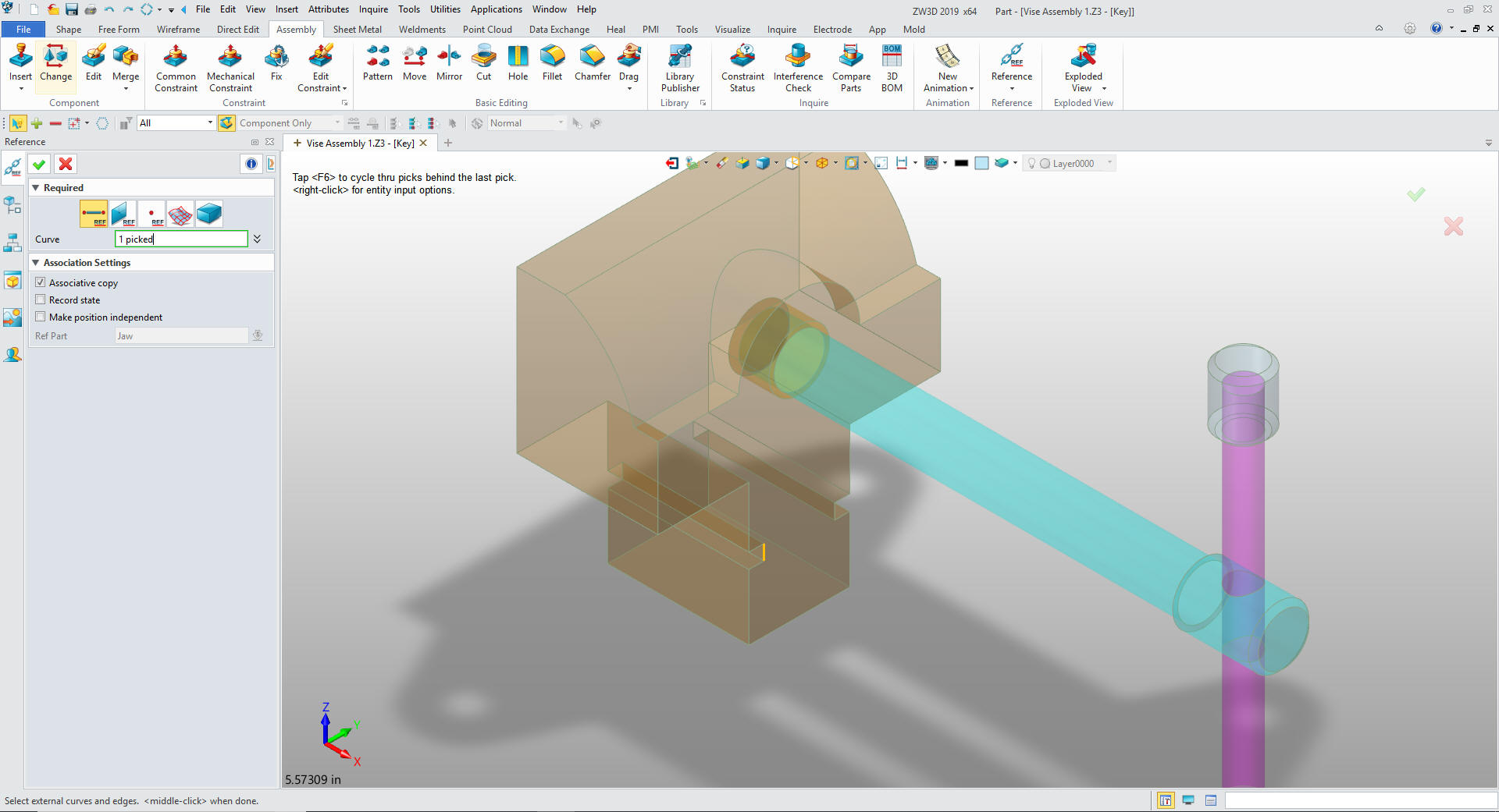
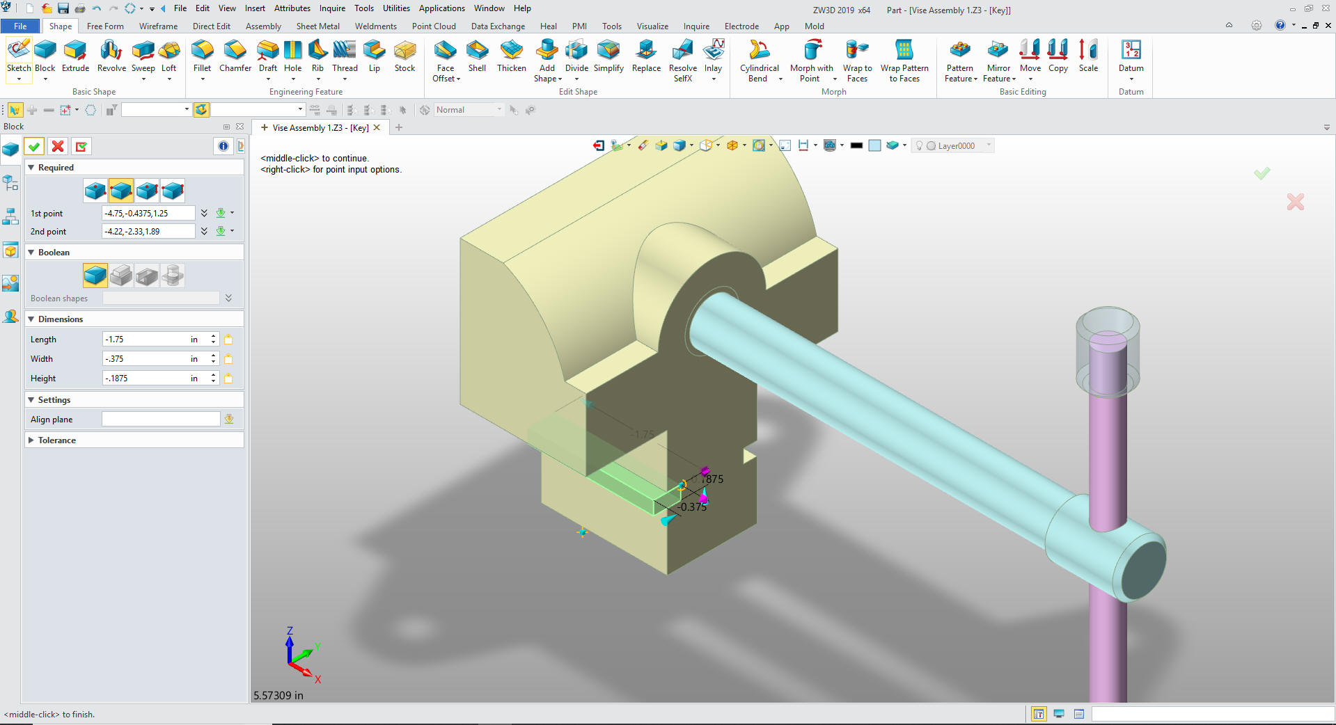
I missed the Keys. Well let's get it done. We insert the Key
component. We hide the Base and go to the assembly mode and
reference the inside edge of the key slot of the Jaw.
We
insert a corner primitive block at the inside upper corner of the
slot, set the size.
We
insert it and move it. And now we are done again.
We blank or
turn off the reference entities.
This is not only top down
and in context but it is in one file.
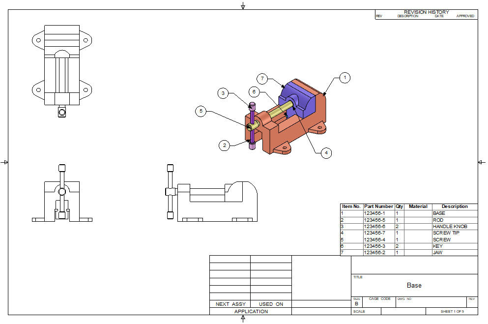
Here
are the AID (Associated Information Documents (drawings))
It is
very important that you look into how you or your engineers are
creating the parts. Streamline Sketching and Feature Based Modeling
is easy to learn and implement. It, alone, will increase
productivity 10X. Now, ZW3D with its unique history and robust
direct edit functionality can increase your productivity another 5X
or more with changes! Again, time is money in engineering.
More on StreamLined Sketching and Feature
Based Modeling.
To experience this increased level of
productivity, please download ZW3D for a 30 day evaluation. Legacy
data is no problem, ZW3D can read the native files of all of the
popular programs including the PMI data of NX, Solidworks, Catia and
Creo. ZW3D is a great replacement for the subscription only Autodesk
and PTC products.
Give me a call if you have any
questions. I can set up a skype or go to meeting to show this part
or answer any of your questions on the operation of ZW3D. It
truly is the Ultimate CAD/CAM System.