3D Modeling Techniques
ZW3D vs Solidworks Lesson Fifteen Of
Course It is an Assembly! Streamlined Sketching/Feature Based Modeling
Modeling note:
It is funny,
you may not realize how you model because you have many ingrained
processes from the past. I have been doing Boolean (direct edit)
design since the beginning of solid modeling in CAD. As I have been doing these comparisons I
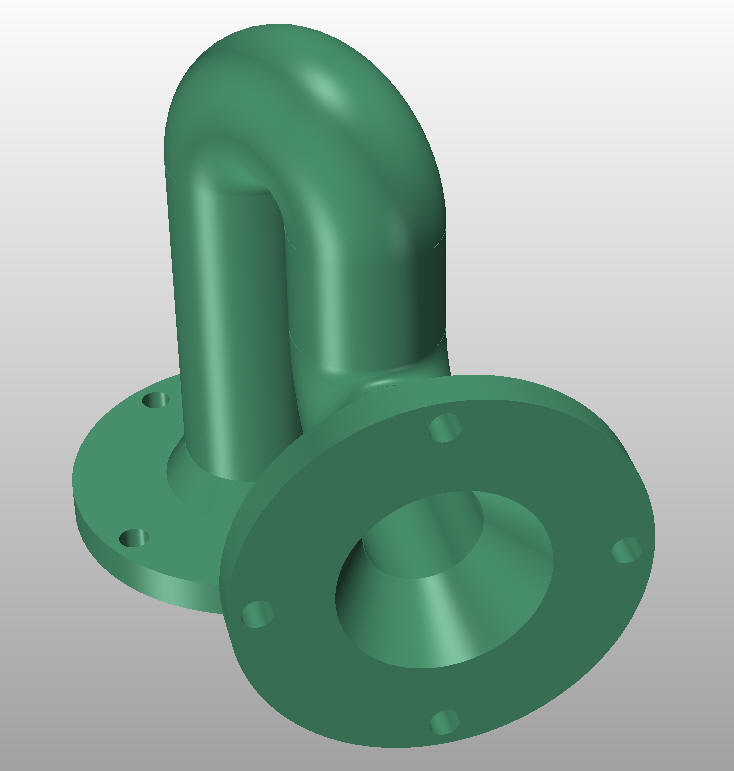
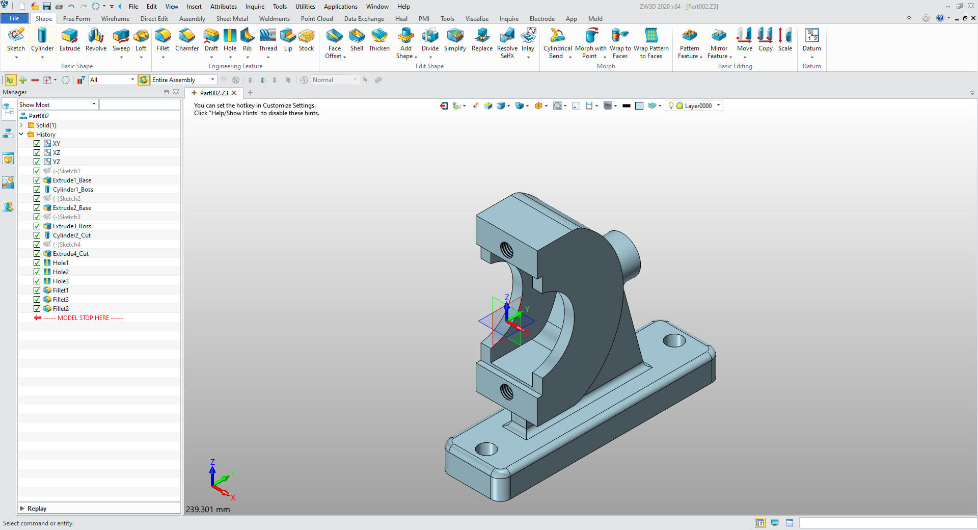
realized that I design in shapes. ZW3D has primitive shapes and
robust direct edit functionality. I look at the drawing and pick out
the basic shapes of the part instead of creating a sketch. You can see that in this part.
This model should be an inseparable assembly. When
you are teaching someone 3D CAD the models should represent real
design. In this case we should be using standard piping fittings.
Teaching 3D Mechanical CAD offers two levels of training: Modeling
and Form, Fit and Function design. Both should be considered when
providing lessons.
ZW3d is a Multi-Object environment, so top down design is a
normal part of our design process. Doing assemblies in Solidworks and
other clones offers different
challenges with creating each part separately. This causes an extra level of
documentation that is already causing chaos in the industry.
The sweep command would be more appropriately
applied for
tube design.
Please watch
as the Solidworks presenter models this part! Even with separate parts, we do
it faster.
While creating 3D models from drawings is the very best
way to learn 3D CAD and maybe some design techniques it does not
expose the designer to the design flexibility necessary in design. IronCAD is all top down due to the single model environment.
Creating mating parts is a cruise. But modeling is just one aspect of a
well designed productive 3D CAD system.
ZW3D vs Solidworks
I would do a
video, but I really am not good at it. So I will show you step by
step. I will try and get ZW3D support to create one. They are
very good.
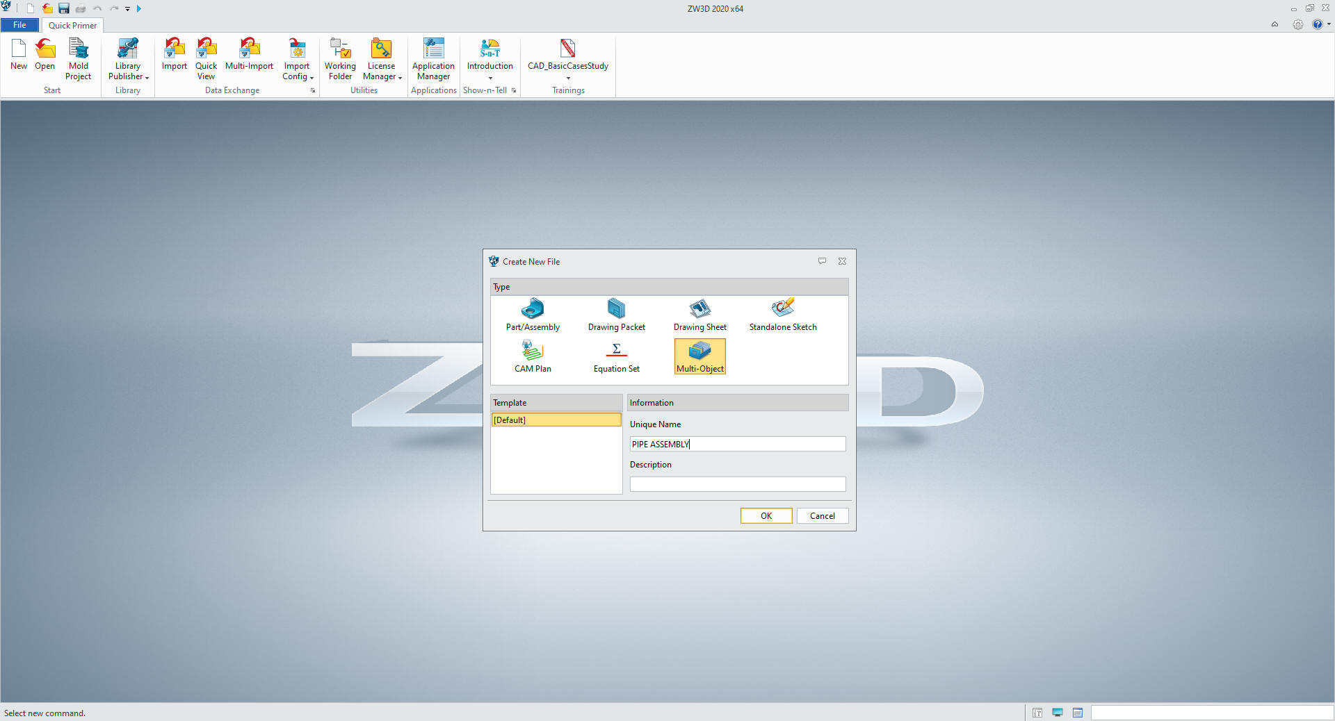
We open a new file and select
multi-object environment which sets up up for and assembly.
I
first go do configuration and set the units to MM.
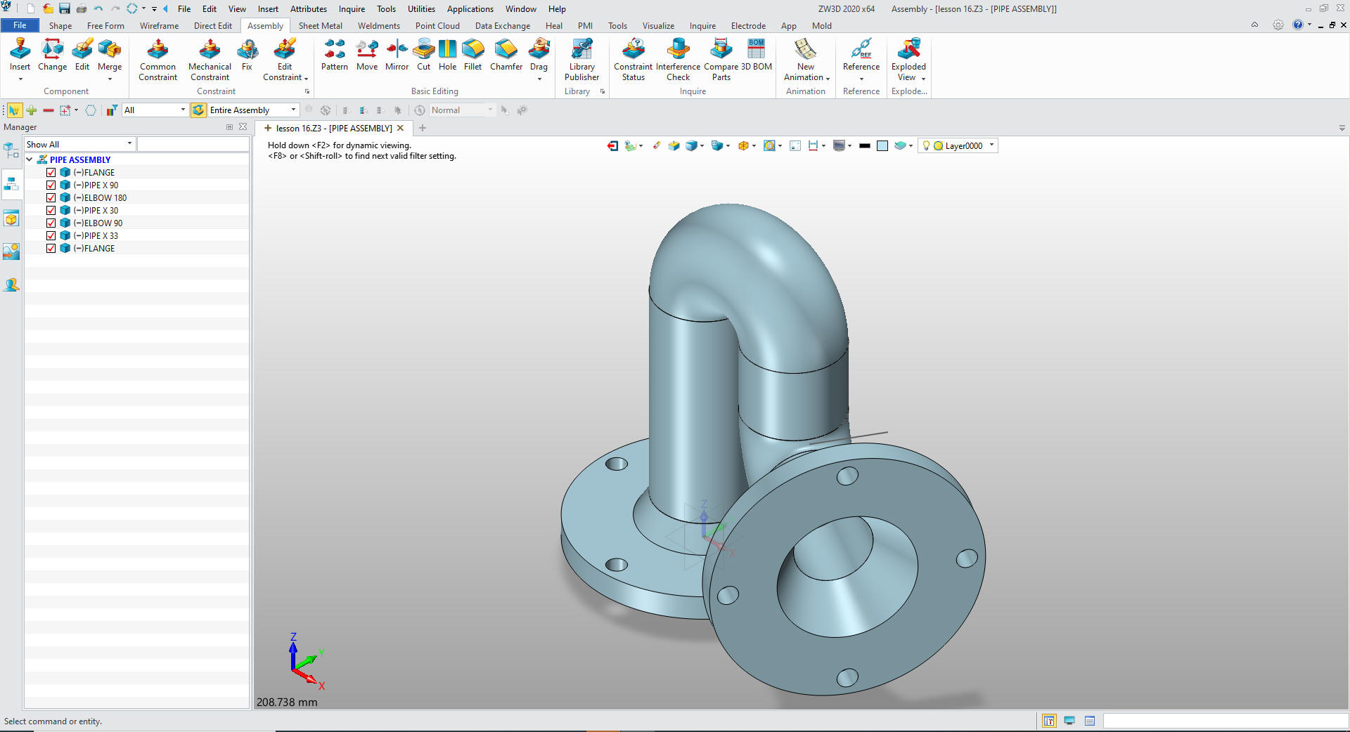
We
now create the top assembly "PIPE ASSEMBLY"
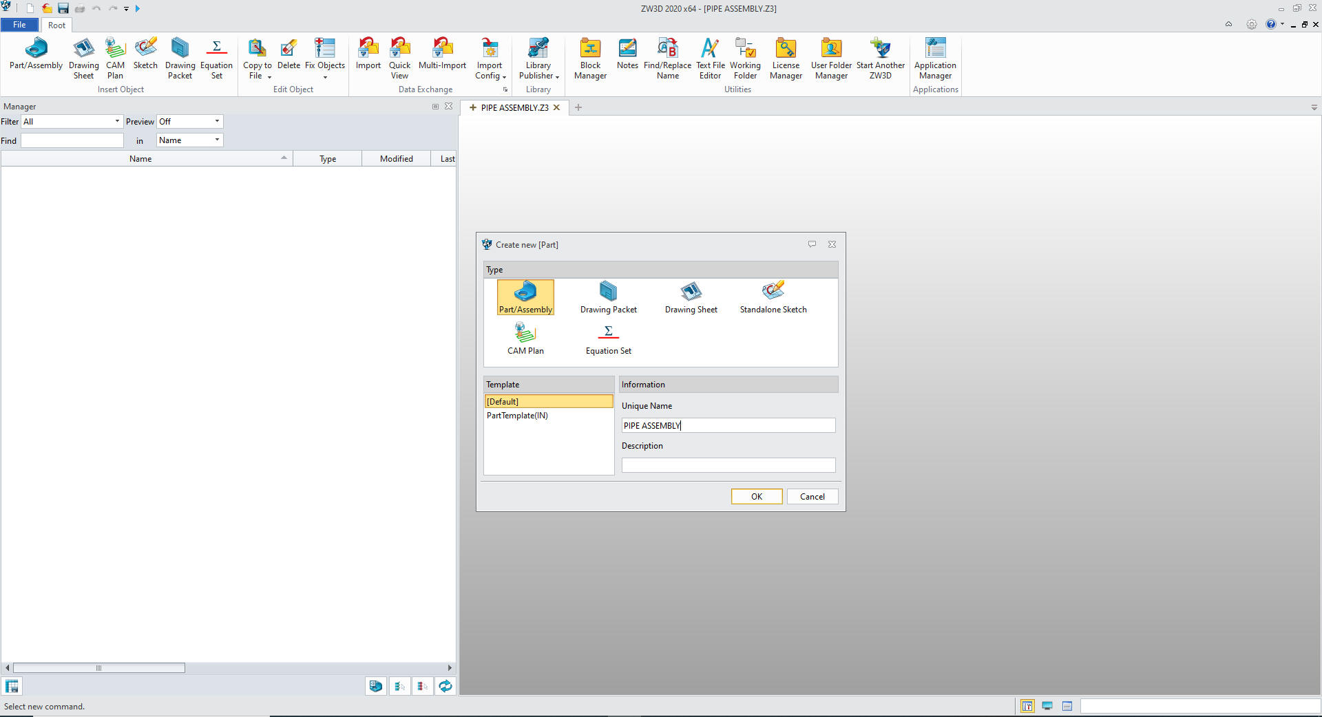
Note: When doing production
design you can use the Multi-Object file to create a component under
a top assembly. You then could keep a legacy of modifications or similar
components in a single file
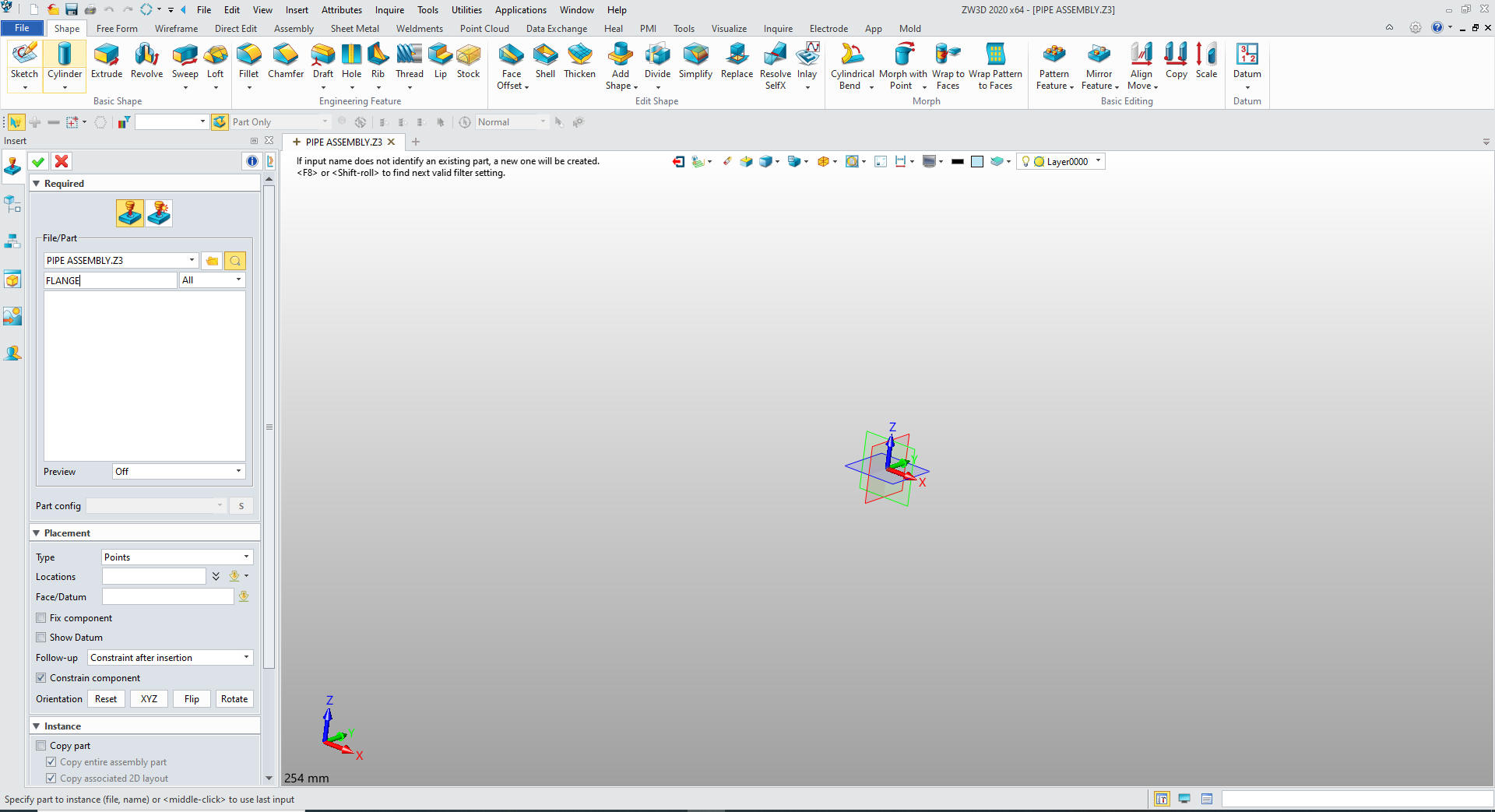
Our first component will be the flange. So we insert a component
under PIPE ASSEMBLY and name it FLANGE.
We are already in millimeters so lets get started.
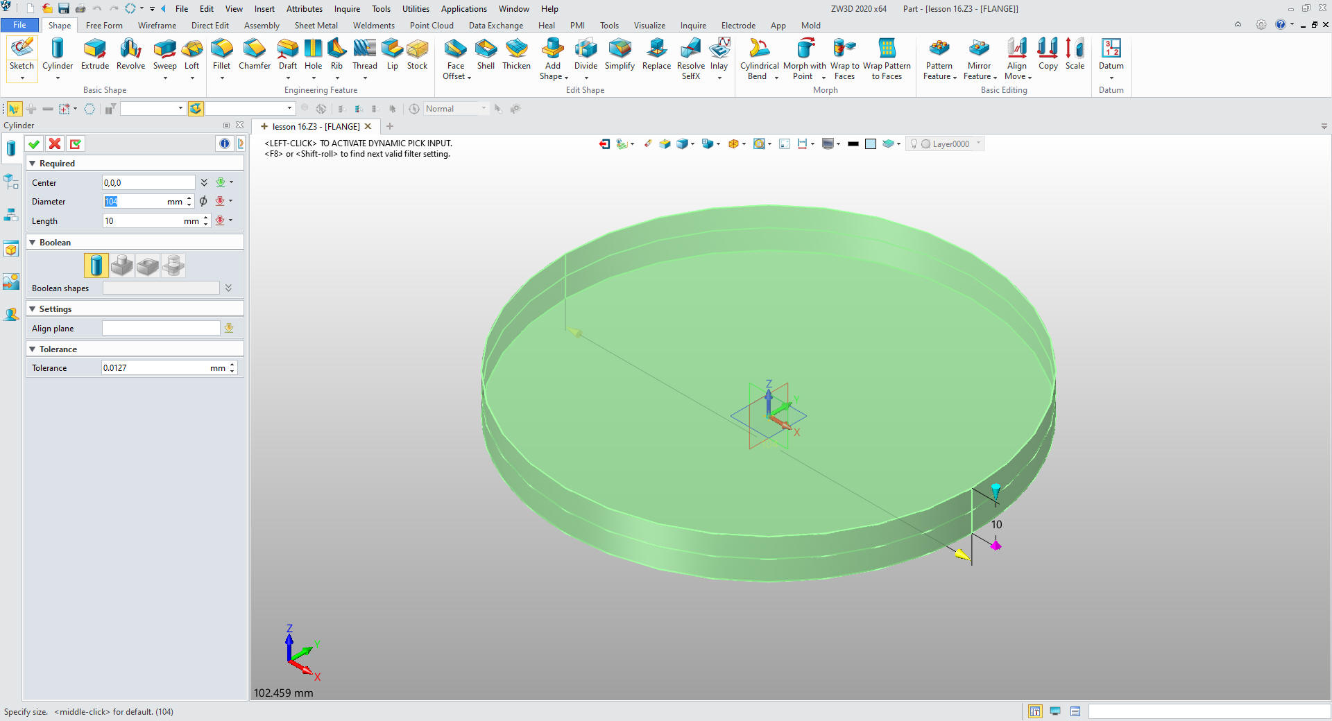
We insert a primitive cylinder at X0Y0Z0, orientate it and size it.
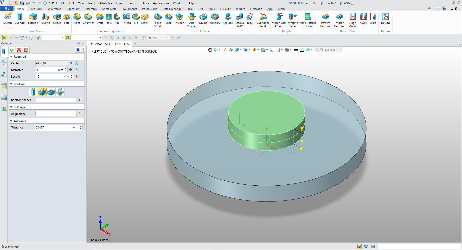
We insert another primitive cylinder at
the center of the top face of the existing cylinder, size it and set
to add.
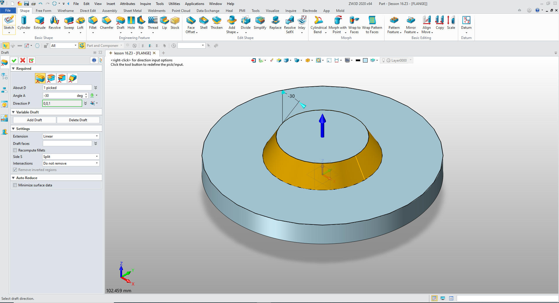
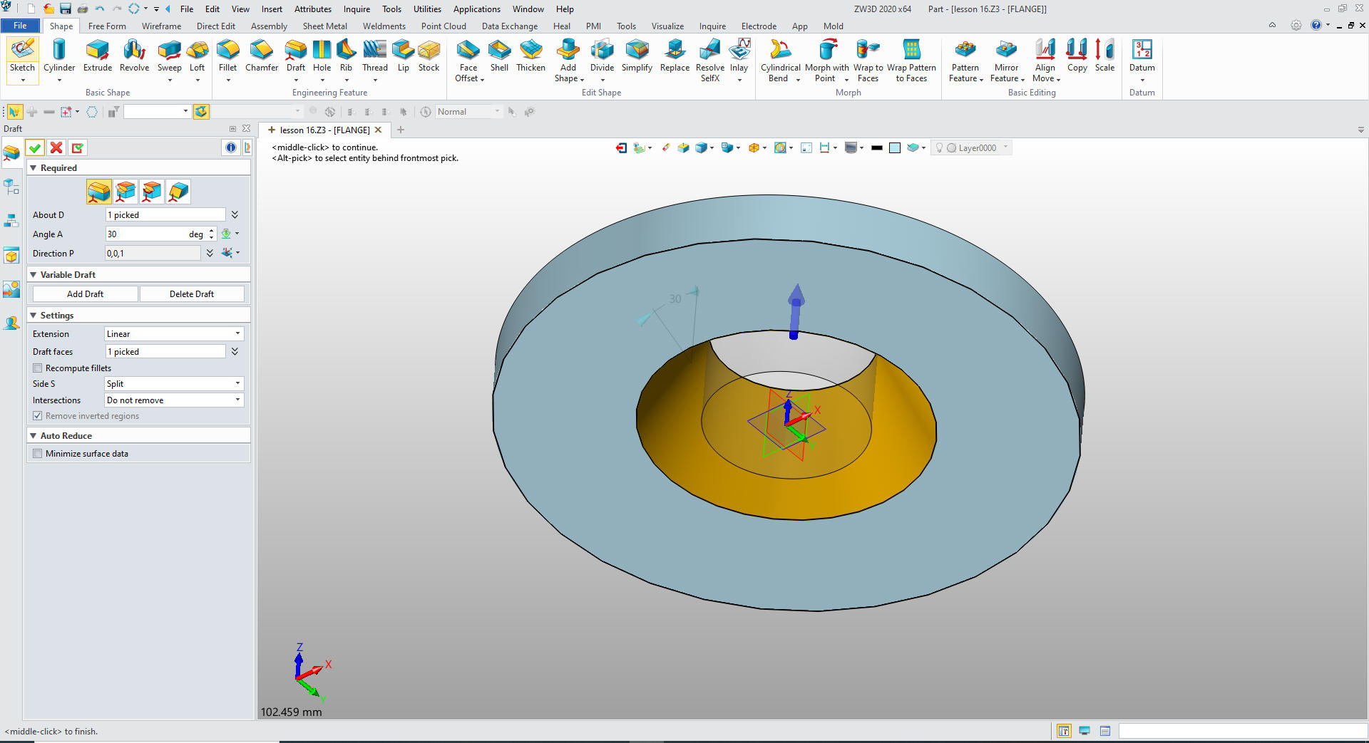
We will now do a Feature Based design
command. We will use the draft command to set the sides 30 degrees.
Now you can watch the Solidworks presenter create a sketch, he is
not trained to work any other way You can see we are designing with
the 3D object in mind.
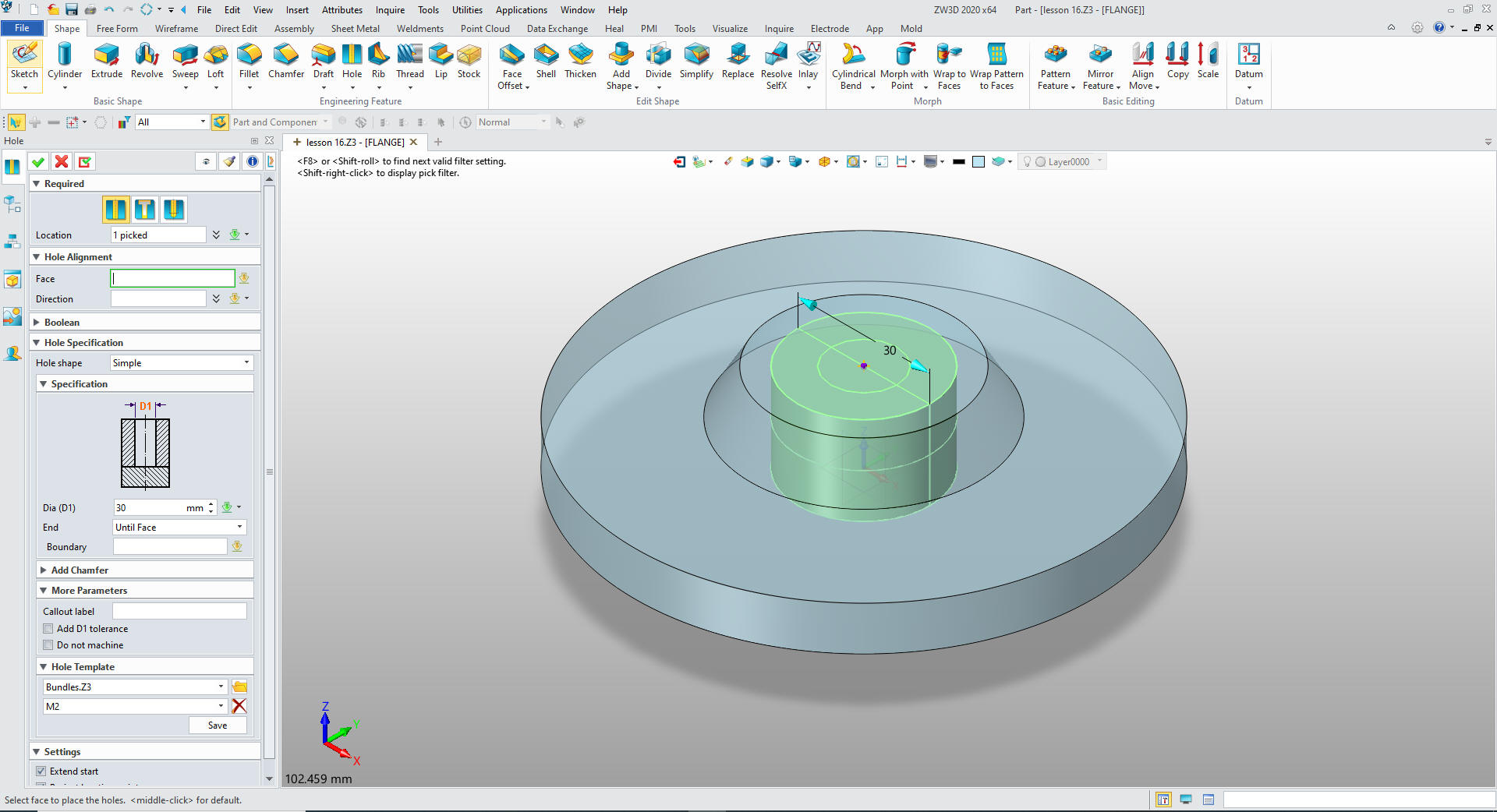
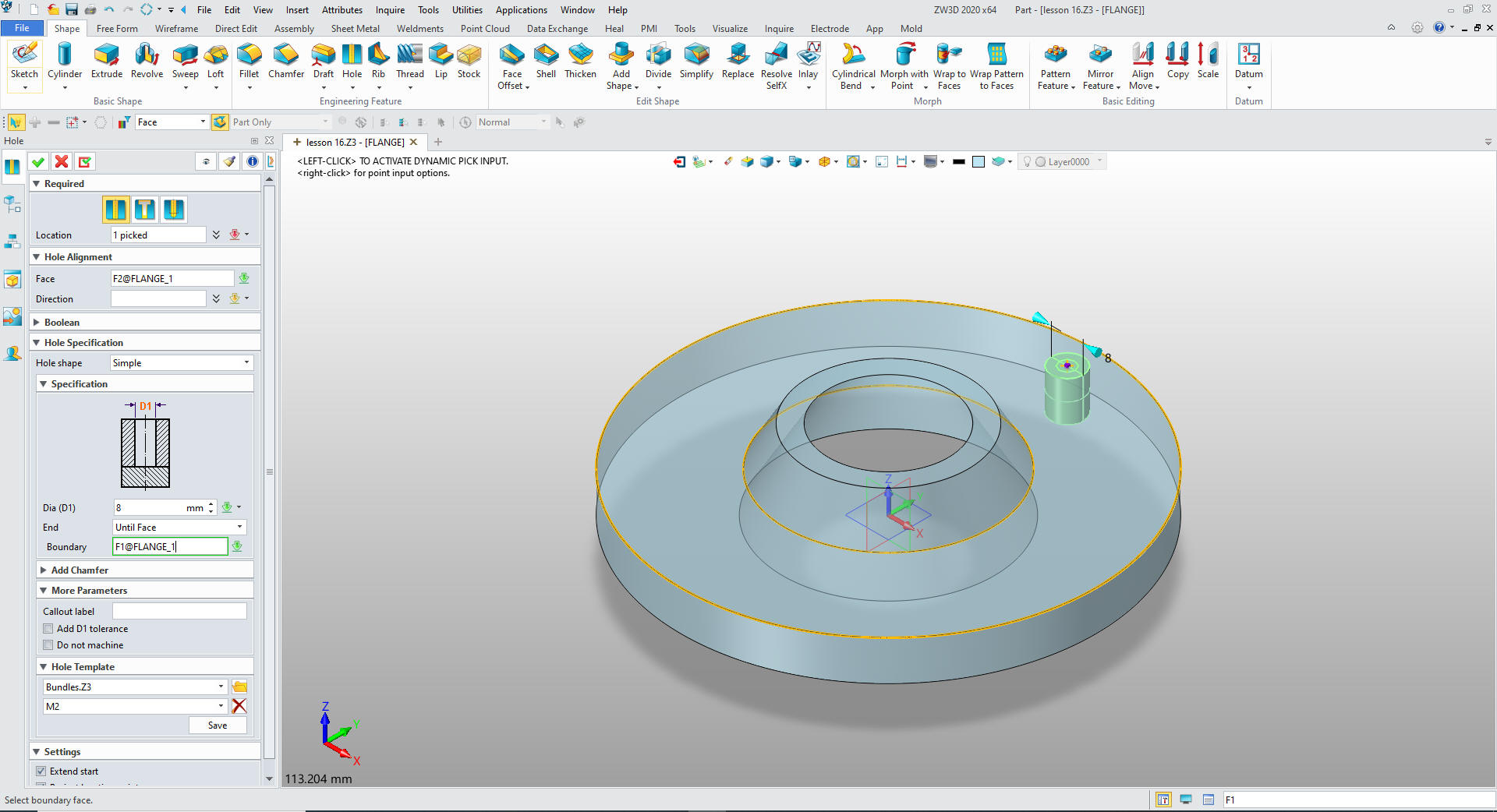
We now use the hole feature to create the 30 mm hole.
We
again use the draft command and set it to 30 degrees
We
will create the create hole feature for the bolt circle. We set the
face and just offset from the X0Y0C0.
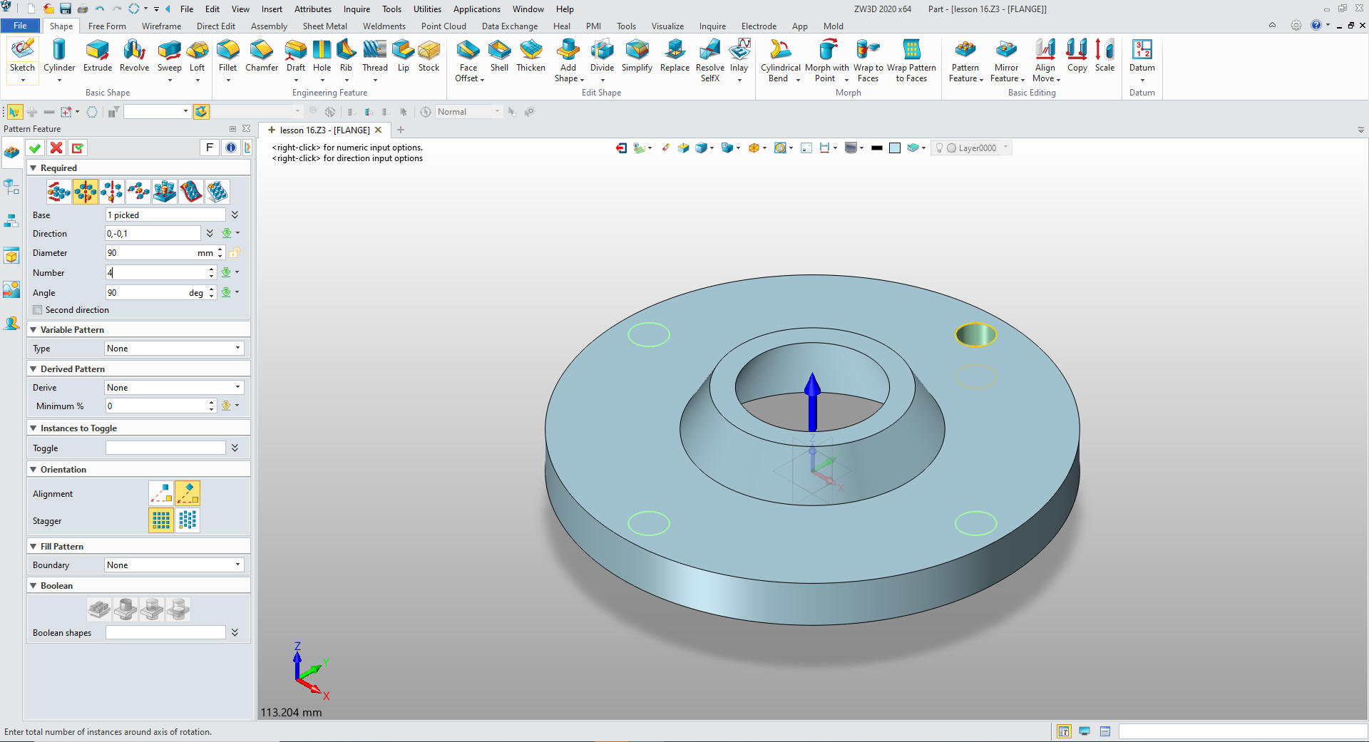
We
just pattern the hole and we are done with the FLANGE.
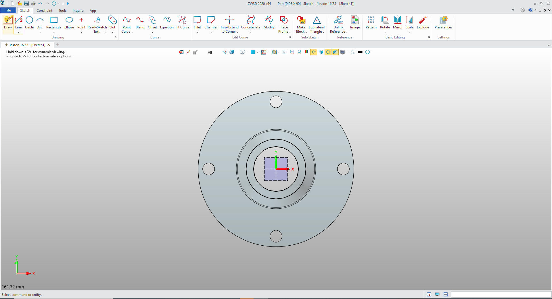
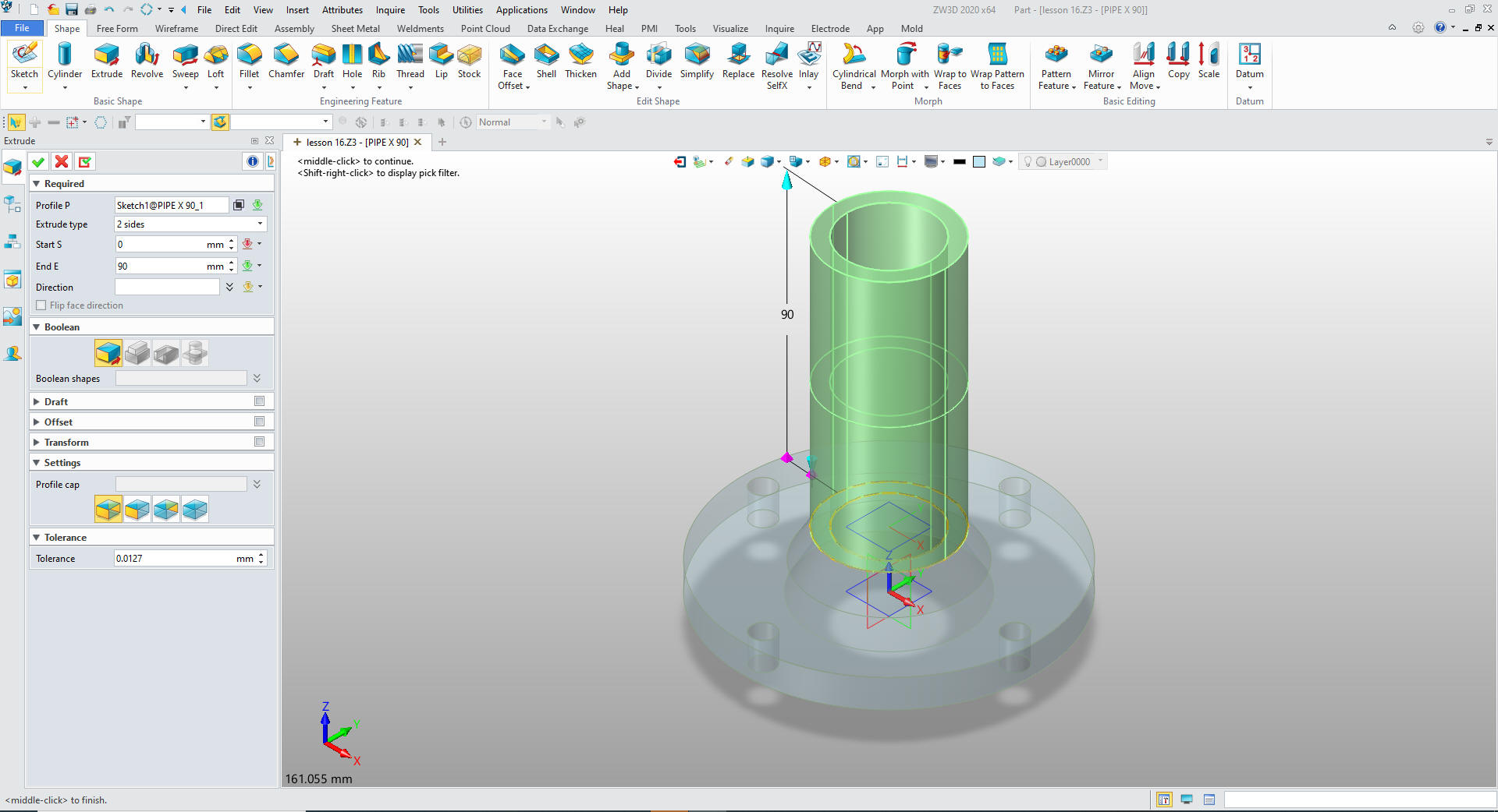
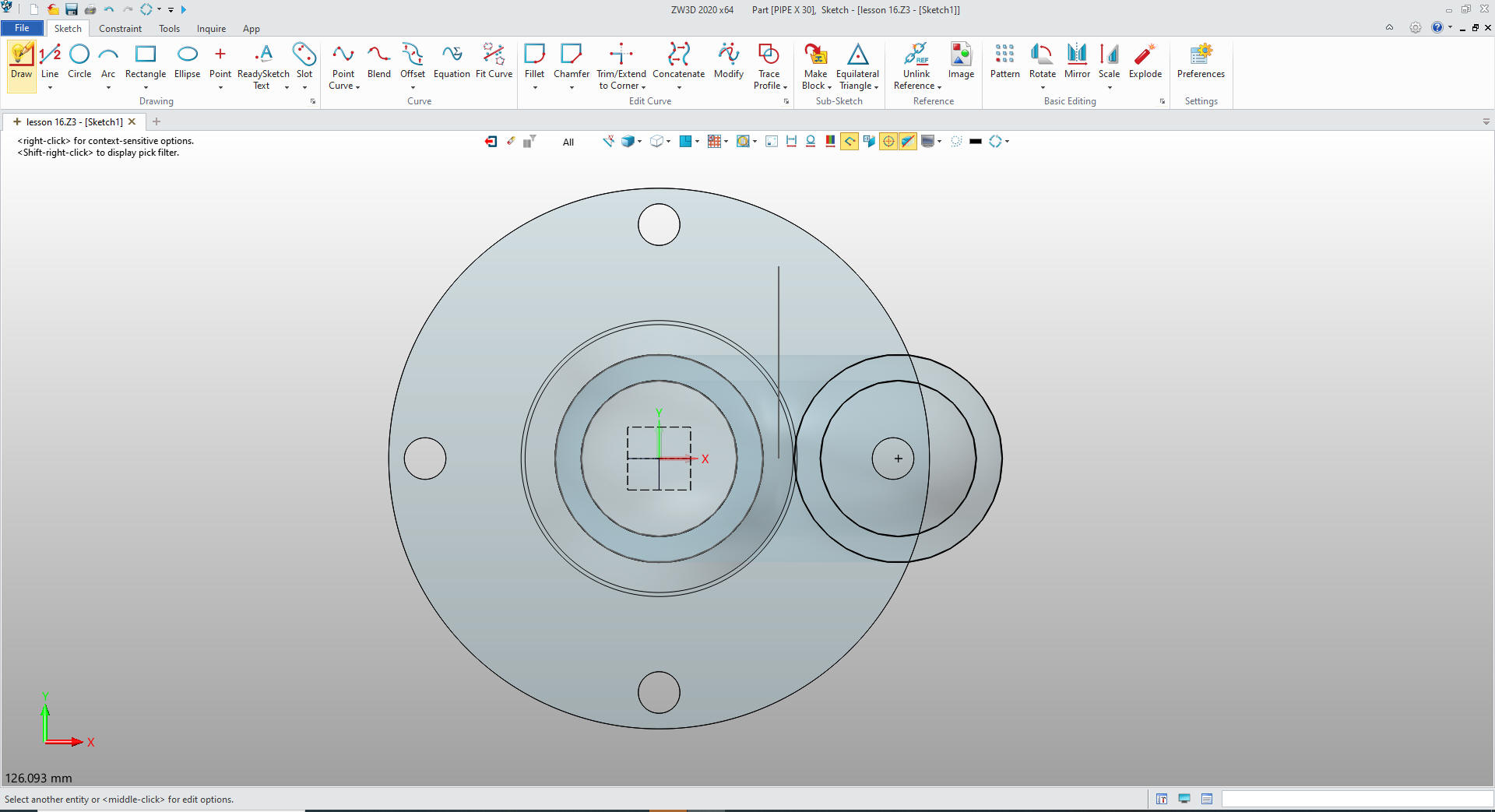
We insert another component under PIPE ASSEMBLY and name it PIPE X
90 create a sketch on the top of the face.
We create
references of the two circle then unlink reference making them
entities.
We
exit the sketch and extrude the profile to 90 mm.
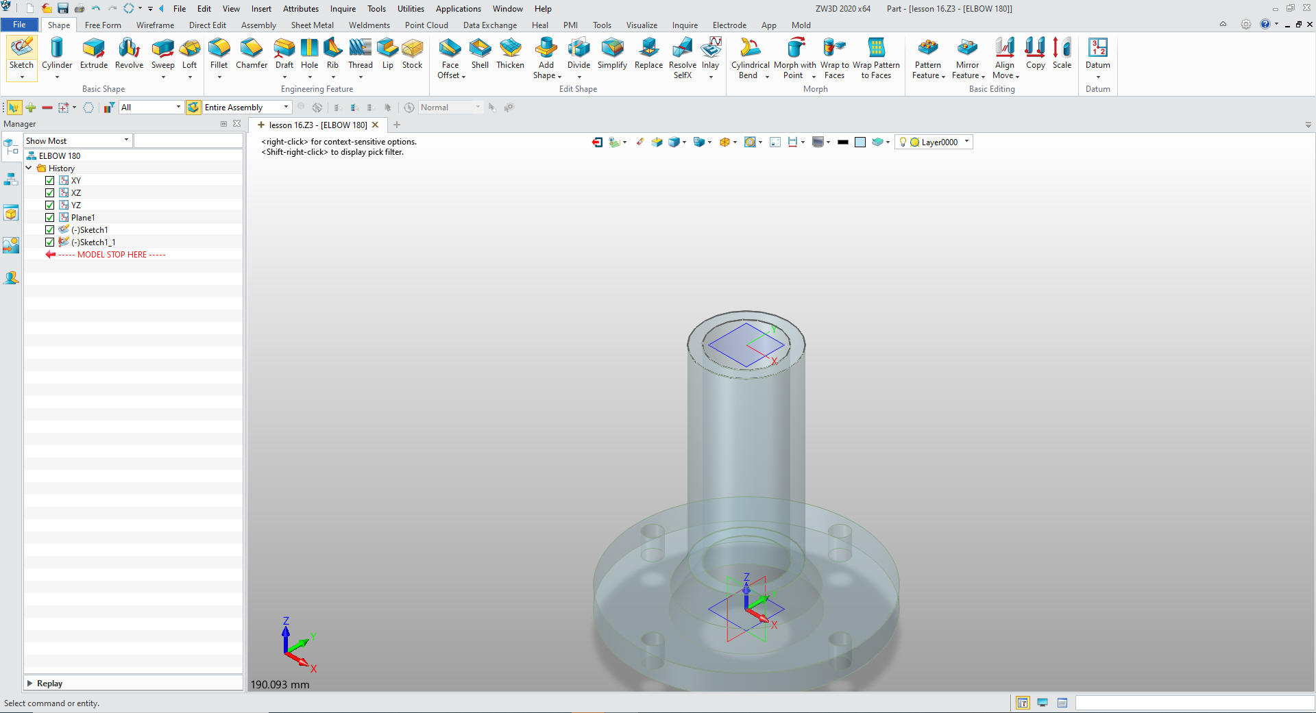
We insert another component ELBOW 180. Set a plane and create
the sketch and again create the reference entities the same as we
did before and exit the sketch.
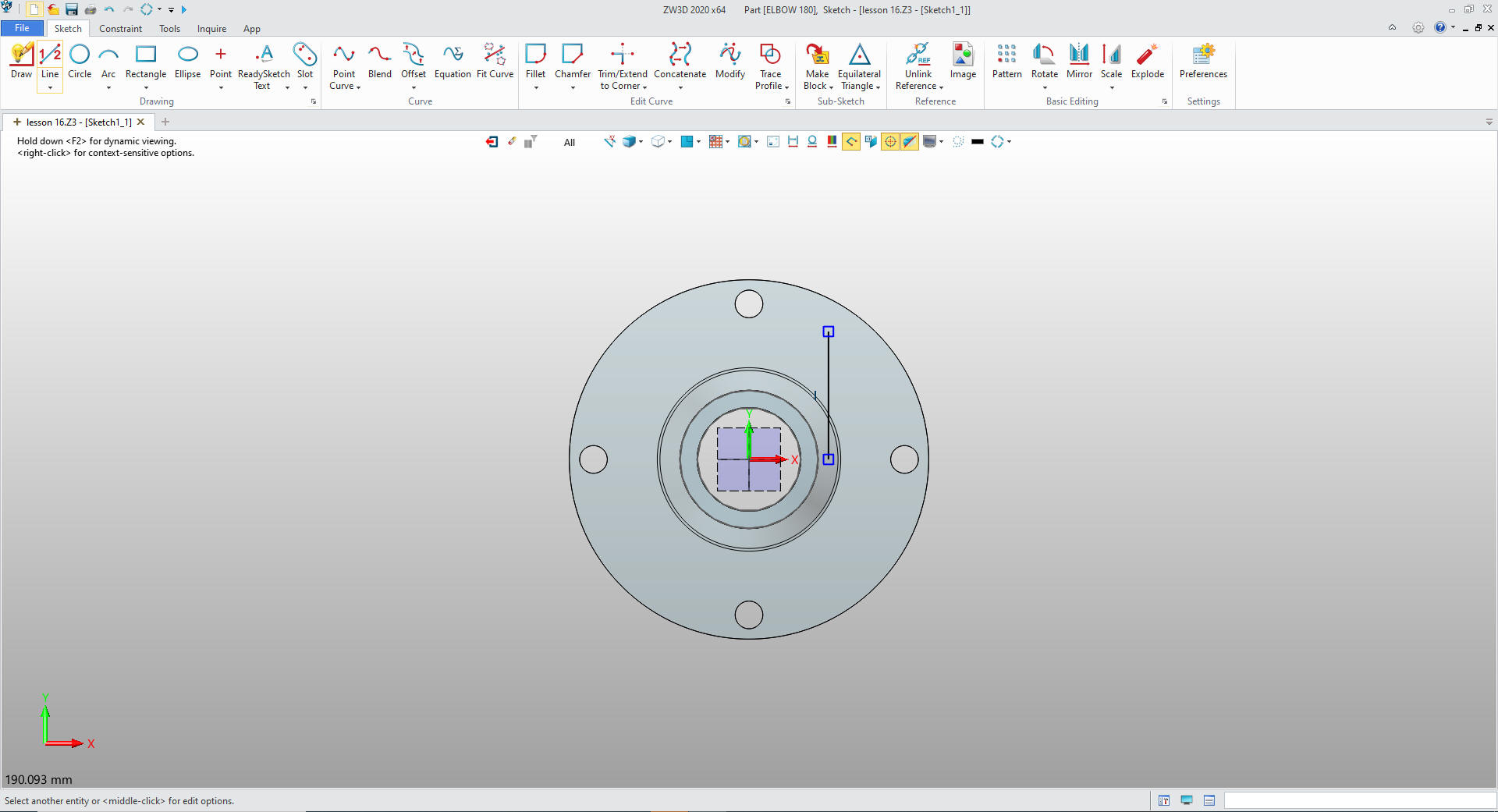
We copy and paste the sketch.
We
could put in the axis for the rotate for the elbow in 3D, but just
defining it as a sketch is a bit easier. So we edit the new sketch,
delete the circles and add the axis line
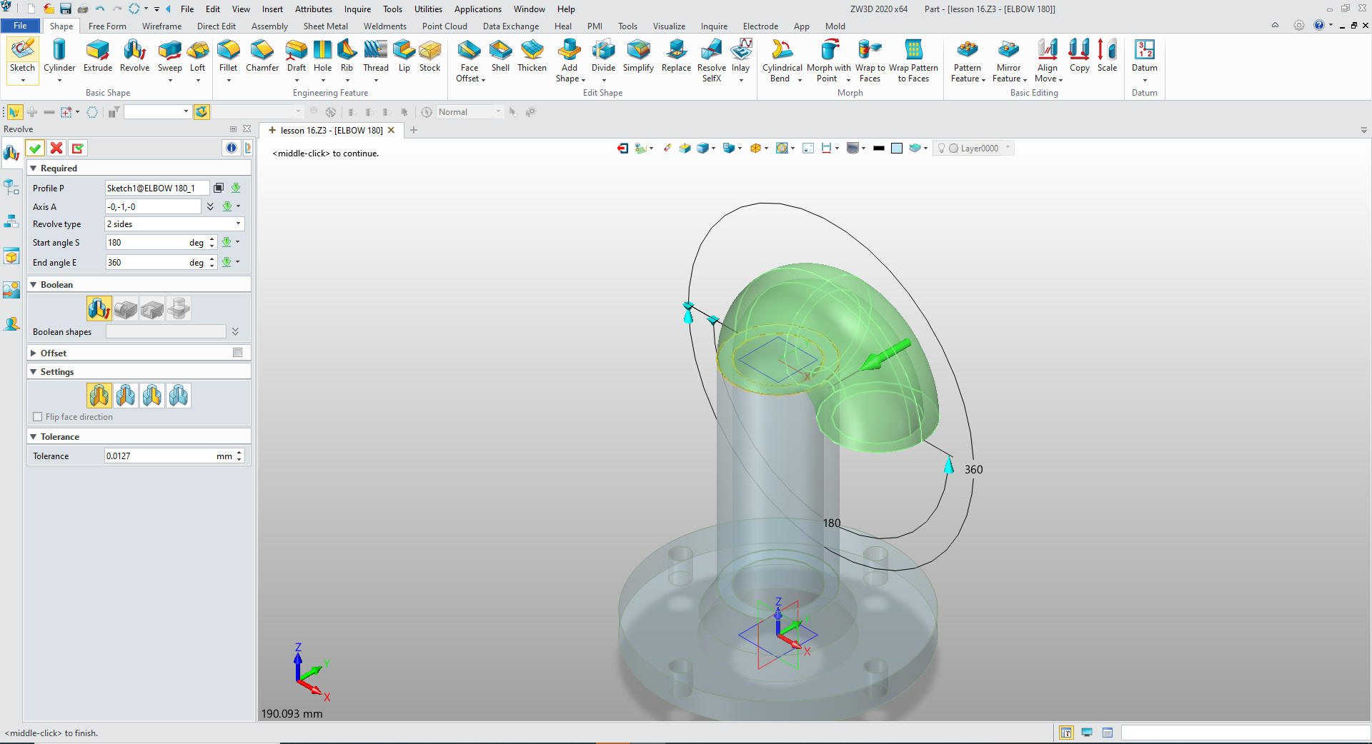
We exit the sketch select the revolve command, select the profile
with the circles and then the axis and set it to 180.
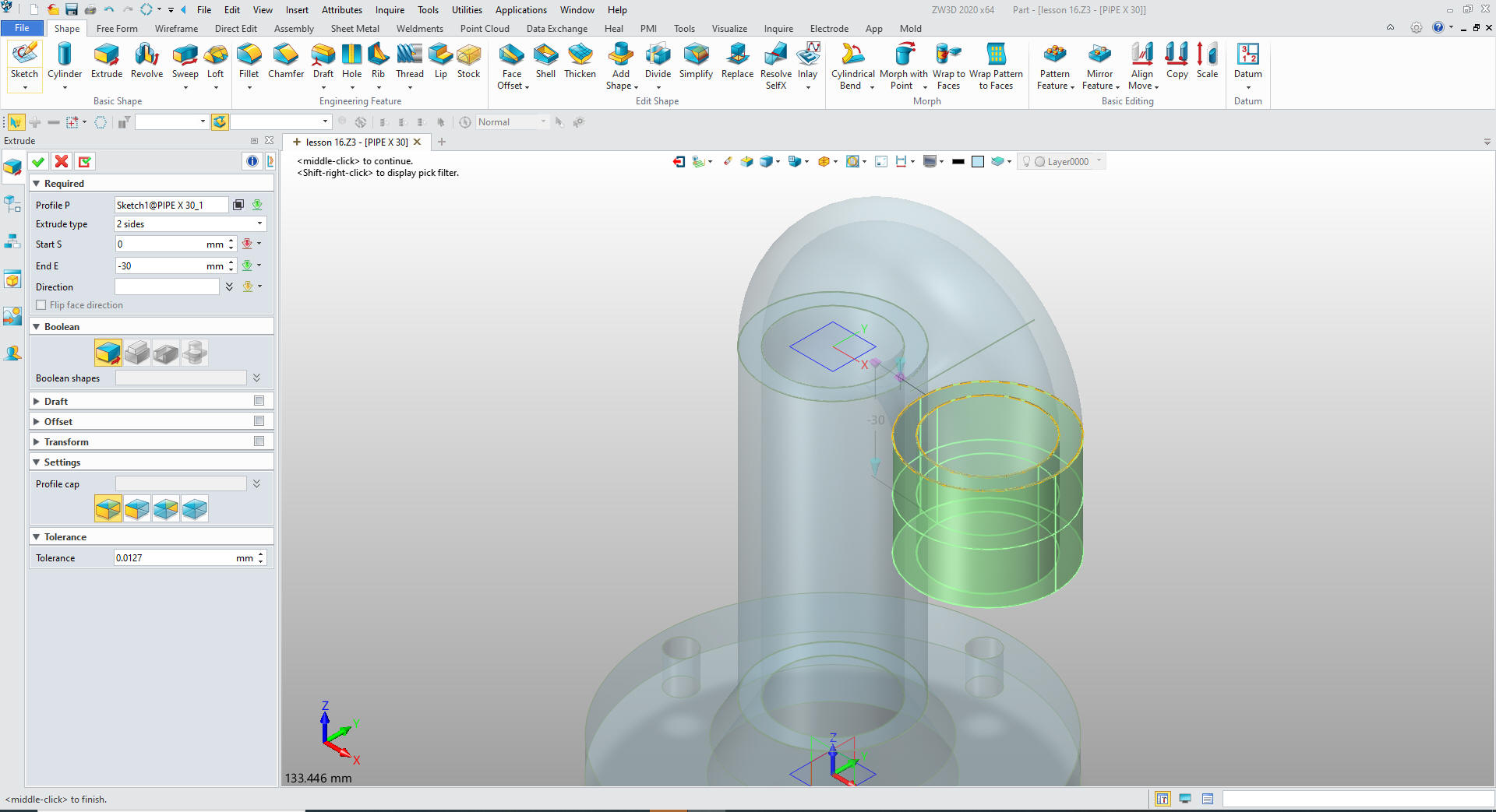
We insert component PIPE X 30. We create a plane (This is a new
component we have to create its own reference geometry. We create a
sketch create the reference geometry and unlink reference.
We
exit the sketch and extrude it 30 mm
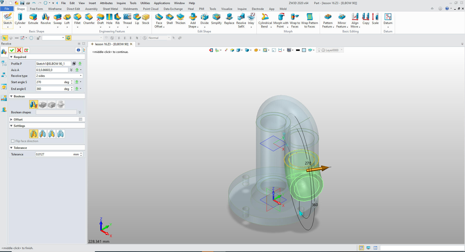
We
insert a new component under PIPE ASSEMBLY called ELBOW90. Create a
plane and again create the reference circles and unlink them. We
then copy the existing sketch and paste it and edit it by deleting
the circles and adding axis for the rotation. Notice it is set at
the 30 degrees.
We
create a datum plane on the face of the elbow and create a sketch,
create the reference circles and extrude the profile 33 mm as I have
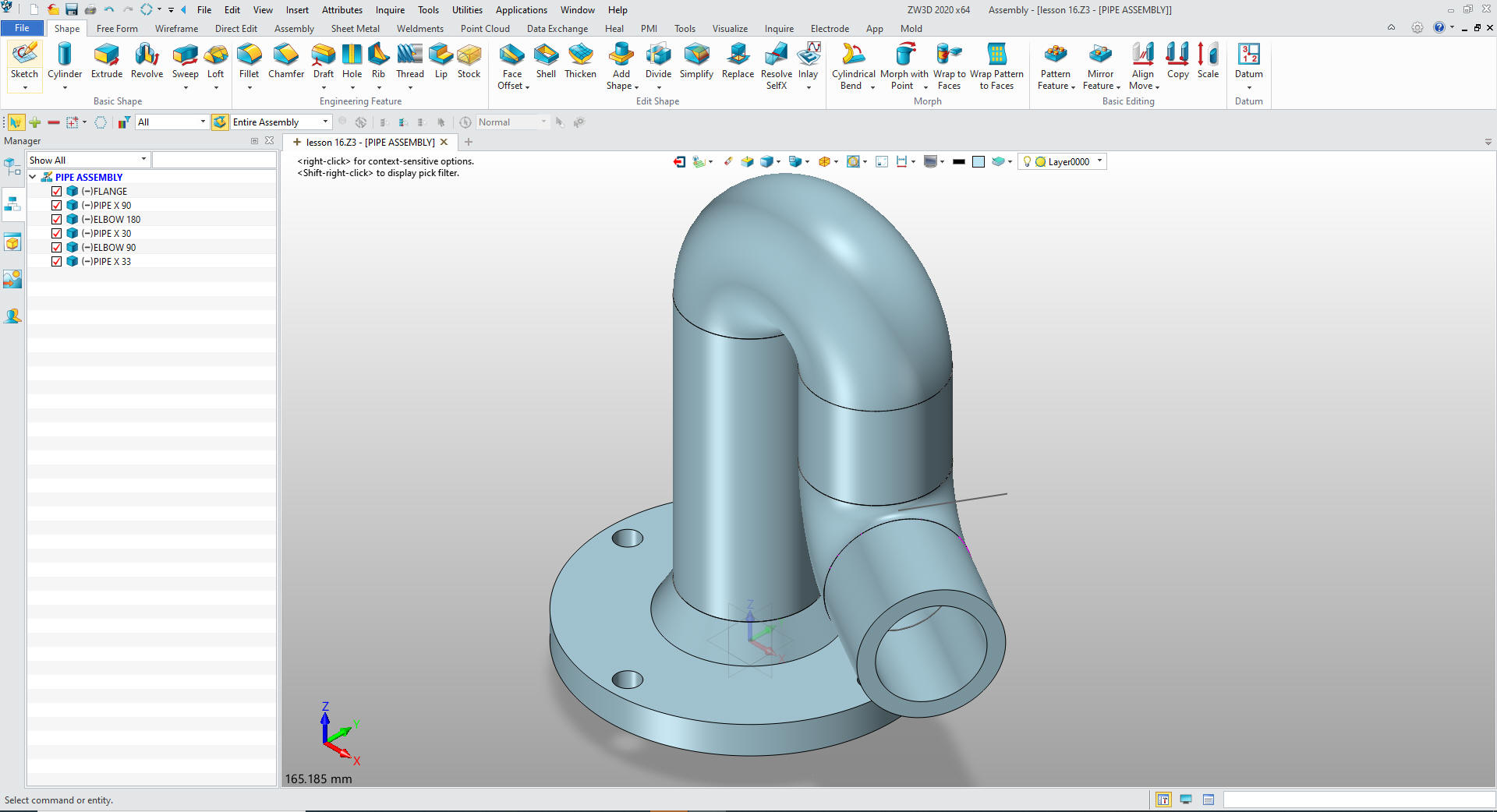
done before. We activitate the PIPE ASSEMBLY
We go
to the Assembly Menu to copy the FLANGE. We copy it and move it into
place and we are done. You can see we now have two FLANGES in the
assembly. Simple assembly design. Doing things right.
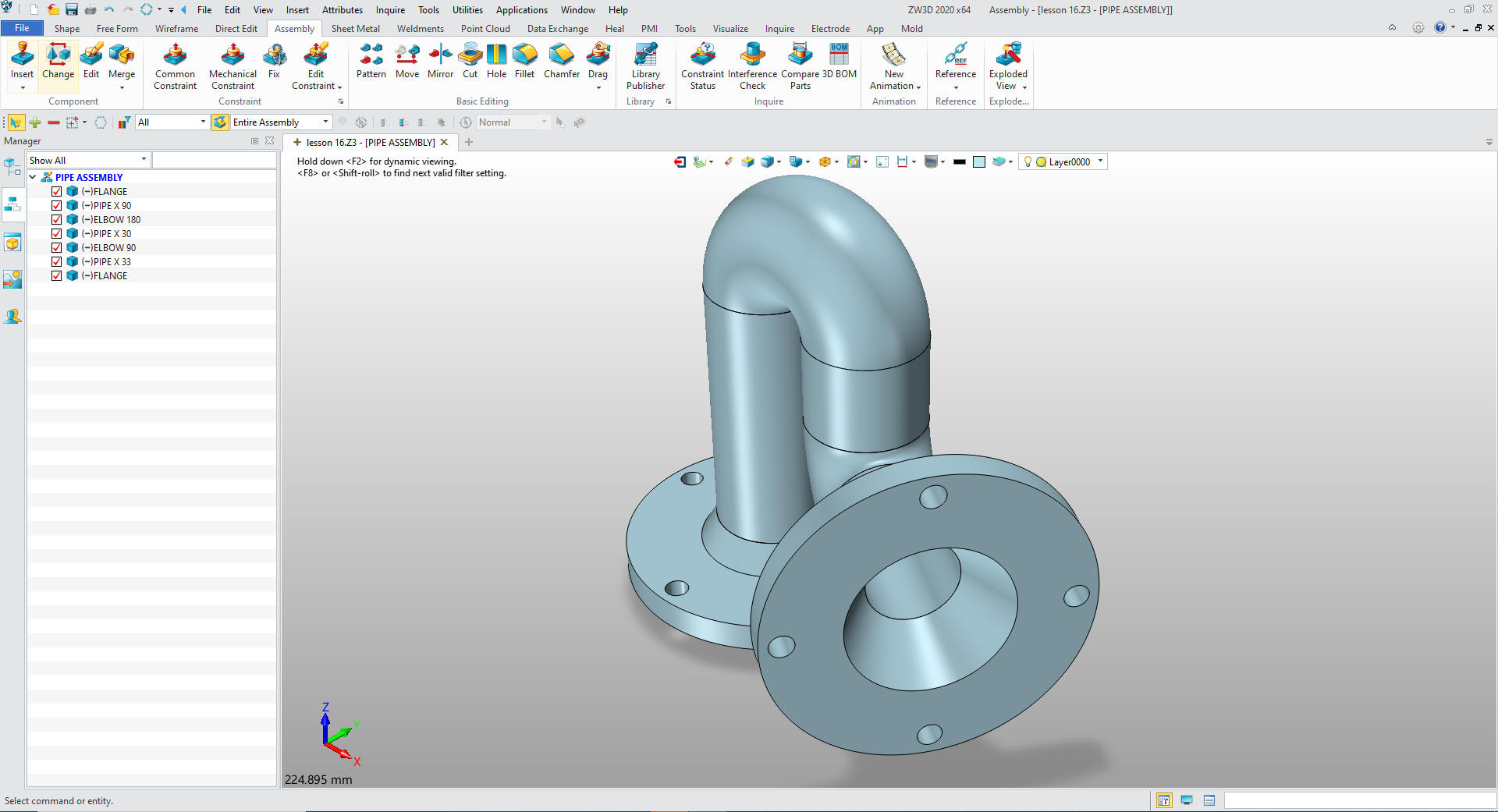
We clean up the components by blanking
the sketches. I should have done this while creating the assembly.
We are done! You can use the StreamLined sketching in any
system, it cuts the time by more than half.
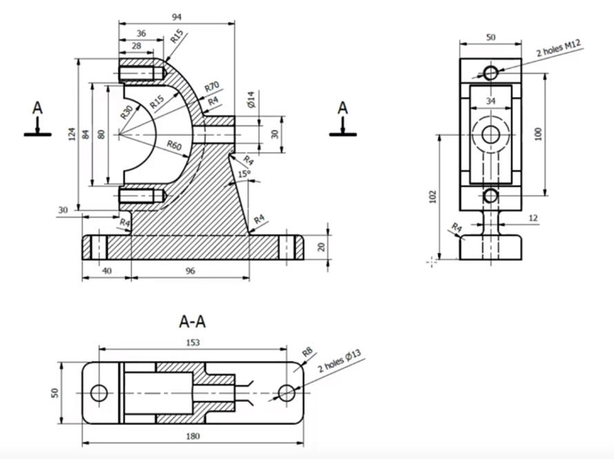
Here is the drawing if you would like to
create the 3D model. the small cut at the left side the side
view.
You can see the two process that ZW3D offers are both hugely
more productive than the tedious constrained based sketching. You
can see more on modeling techniques here.
Give me a call if you have any
questions. I can set up a skype or go to meeting to show this part
or answer any of your questions on the operation of ZW3D. It
truly is the Ultimate CAD/CAM System.
If you are interested in adding professional
hybrid modeling capabilities or looking for a new solution to
increase your productivity, take some time to download a fully
functional 30 day evaluation and play with these packages. Feel free
to give me a call if you have any questions or would like an on-line
presentation.