IRONCAD vs CATIA Lesson 1 3D Modeling Techniques Defined Streamlined Sketching/Feature Based Modeling
The modeling technique is
hugely responsible for the level of productivity. Those of you that
are only trained in the constrained sketching world of the major CAD
systems
are truly limited by not using the freedom of Streamlined Sketching
and Feature Based Design,
that is available in even the most Pro/e-ish of CAD systems. If you
or your
designers are designing in these very unproductive and time
consuming processes it might be time to review your standard design
processes. Don't have any do you?
These
lessons started out as
product comparisons, but quickly turned into a study in 3D modeling
techniques.
When I introduce IronCAD's very
flexible design paradigm I have a hard time to get the Pro/e clone
users, like Solidworks and other programs to understand the drag and
drop design paradigm.
Download
IronCAD/Inovate and take
the one day and 17 lesson course. I get rave reviews from my new
customers. Give it a try, this is a fully functional 30 day
evaluation with all of the native translators so you have access to
your legacy engineering information.
IronCAD Self-Pace Training Course I saw the
following CATIA YouTube tutorial and thought I would give it a
try on IronCAD. I have to tell you it is almost tortuous to watch
the CATIA presenter. CATIA is a constrained sketched based
system as are Fusion 360, NX, Inventor, Solidworks and Creo. This modeling paradigm is used throughout
the industry causing millions of wasted hours.
I was a bit
surprised to see a bit of direct editing in CATIA. IronCAD is the only
integrated History/Direct Edit CAD system and effectively
incorporates and direct face moves instead of adding them as steps
in the history. Direct editing should not be used haphazardly
especially in a history based systems where every face move is a
step! He should have organized the features better so this was not
needed.
I have to say the CATIA
presenter struggle with such a simple part. I cannot imagine the
wasted time CATIA is creating for companies like Boeing, Bombardier,
Airbus, Gulfstream, Chrysler and so many more.
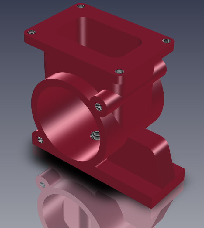
Effective, easy to use part modeling is the basis for all
engineering productivity.
You can see I did the part in a different order so I
would not have to do any direct edit modification. The order of Design in IronCAD
should be Drag and Drop, Sketching, Direct Edit and finally
Surfacing if required.
While creating 3D models from a drawing is the very best
way to learn 3D CAD and maybe some design techniques is does not
expose the designer to the design flexibility necessary in product
design. IronCAD is all top down due to the single model environment.
Creating mating parts is a cruise. But effective modeling is just one aspect of a
well designed productive 3D CAD system.
The drawing is at the
end of this article if you would like to try this lesson. IronCAD vs CATIA
I would do a
video, but I really am not good at it. So I will show you step by
step. I will try and get IronCAD support to create one. They are
very good.
I usually create the part before I watch
the Video, so as to not taint my process, but this time there was no
drawing so I had to suffer through this presentation getting the
dimensions. Of course,
there are a multitude of ways to create a model. There is no right
way, just more productive ways. But from what I have seen from these
very complicated processes done by the CATIA presenter, it is not
just limited by the 3D CAD system.
The modeling technique is
hugely responsible for the level of productivity. Those of you that
are only trained in the constrained sketching world
are truly limited by not using the freedom of Streamlined Sketching
and Feature Based modeling,
that is available in even the most Pro/e-ish of CAD systems. If your
designers are designing in these very unproductive and time
consuming processes it might be time to review your standard design
processes. Don't have any do you?
I have to say this is
incredibly simple. But the CATIA presenter has been
indoctrinated into these designs techniques. It started with Pro/e (Creo)
and has been the way the sketch, constrain and assemble. The
Solidworks clones are costing the industry millions, if not billions,
in lost productivity.
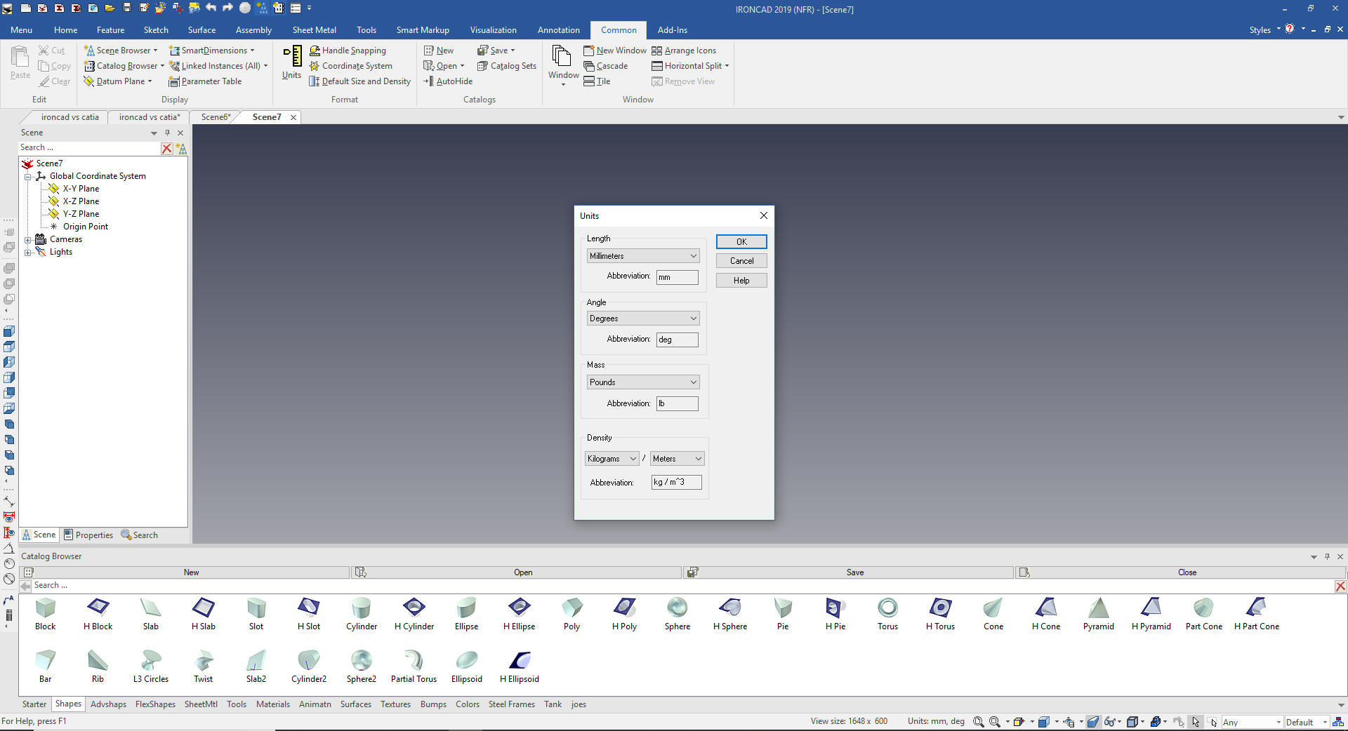
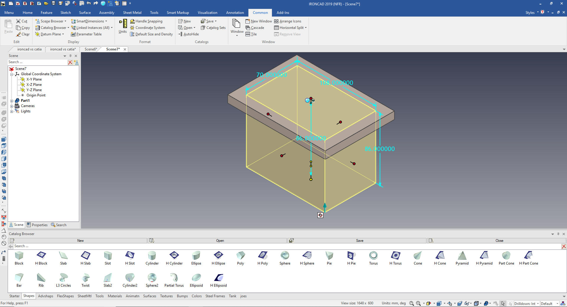
Here is IronCAD. We will set the units
to millimeters.
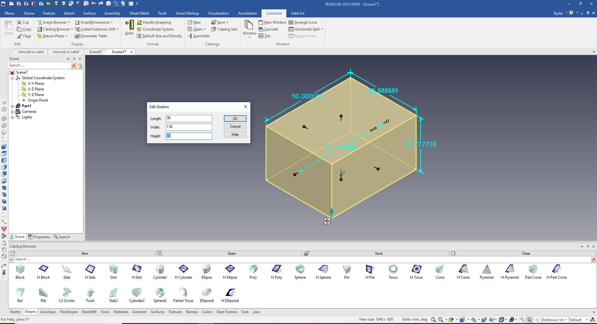
We will start by dragging and dropping a
block from the catalog and sizing it.
What are these shapes? We call them
intellishapes. All are based on sketches that can be edited.
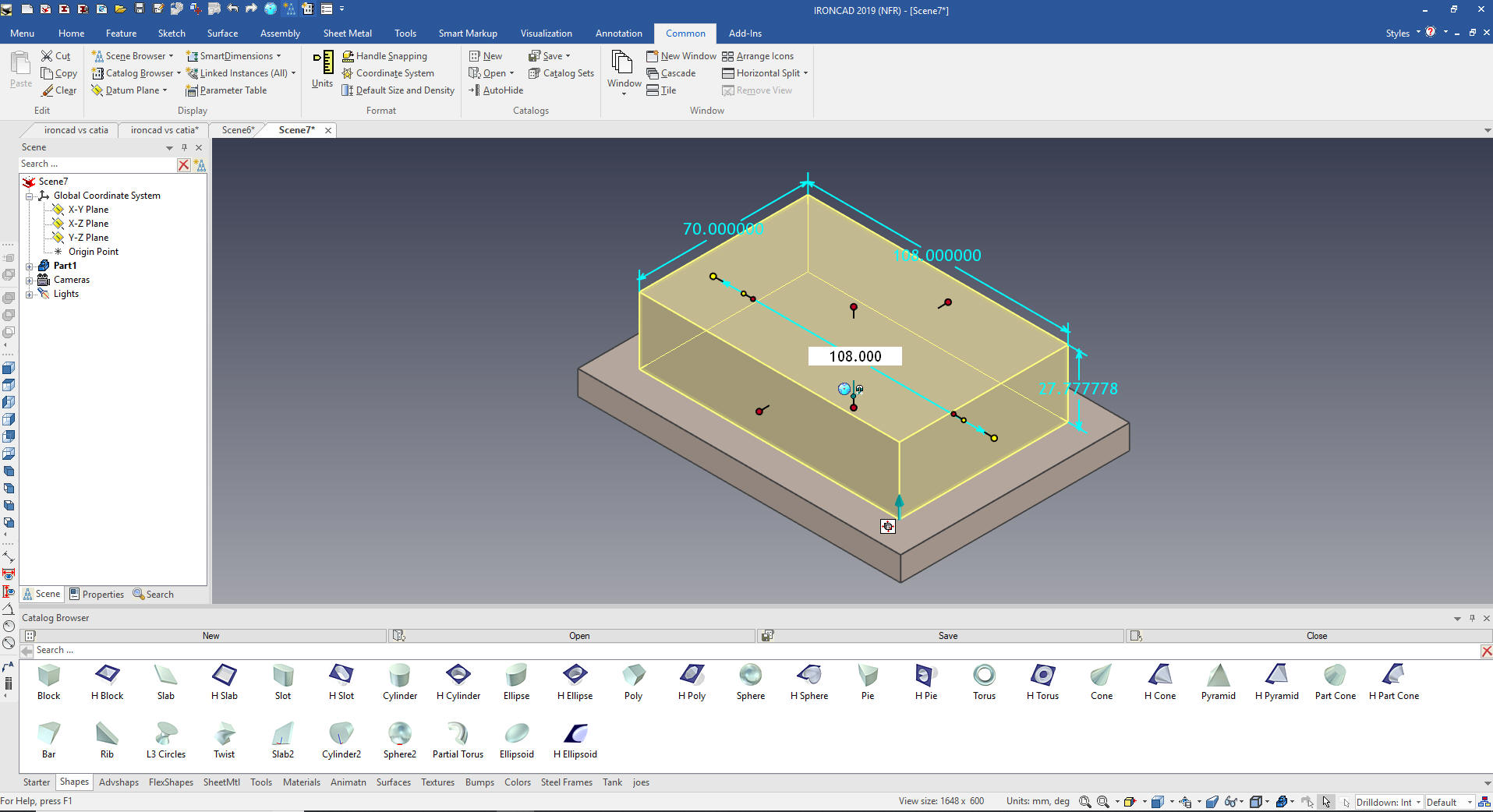
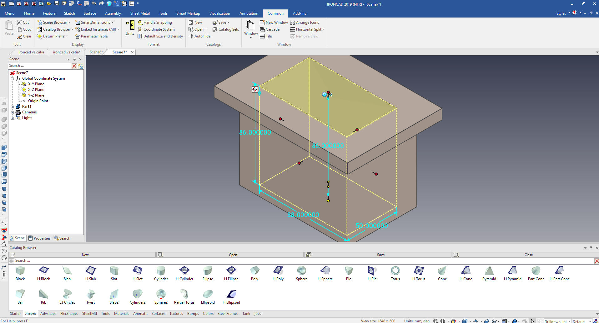
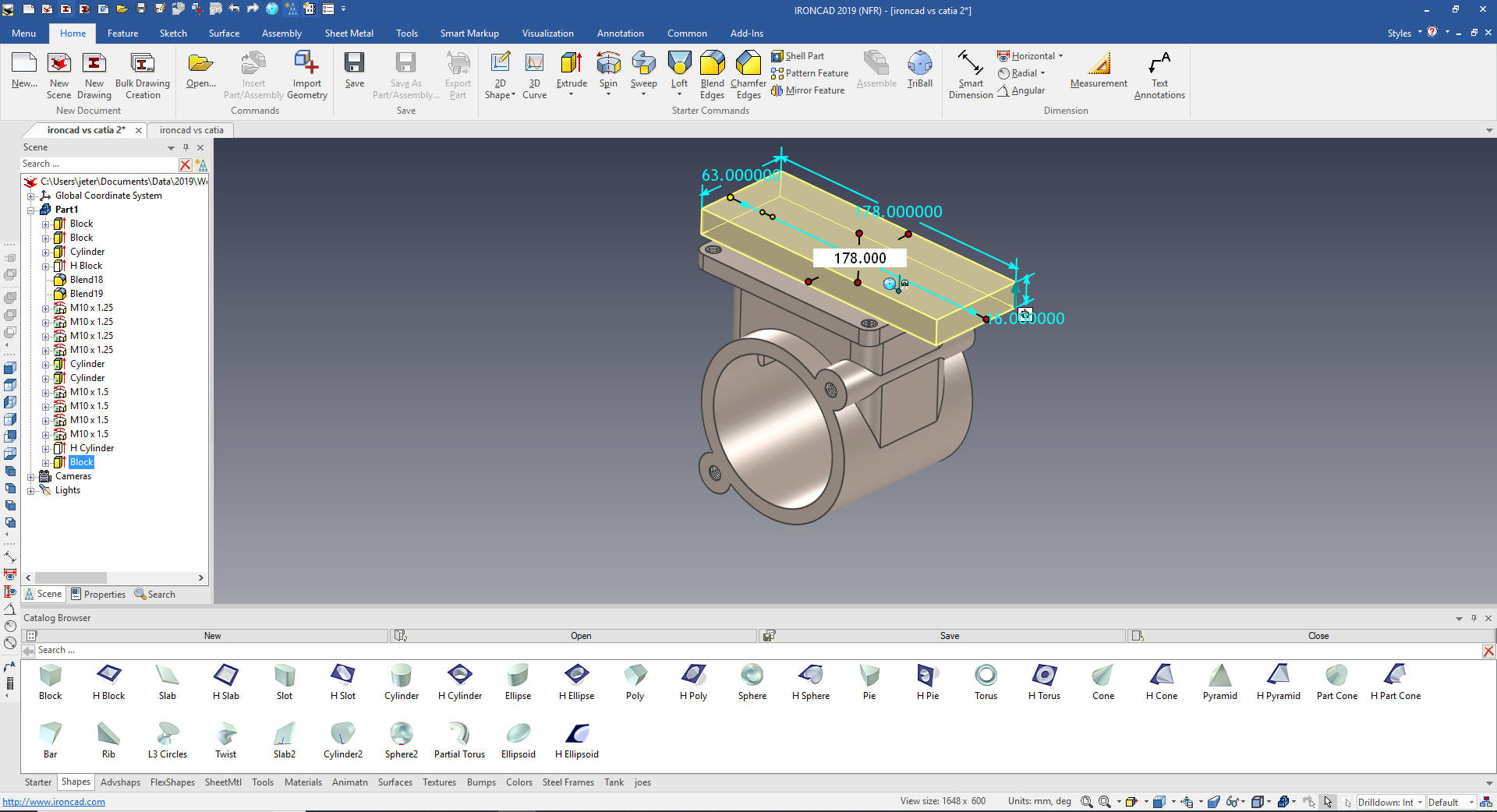
We then drag and drop another block and
position it at mid-point of the top rectangle sizing it as shown.
Location of the Intellishape allows you to size it more efficiently.
Like the length and with are size with symmetry in mind.
We use the handles to pull it into place
and size the depth.
We drag a hole block to the mid-point
and size it.
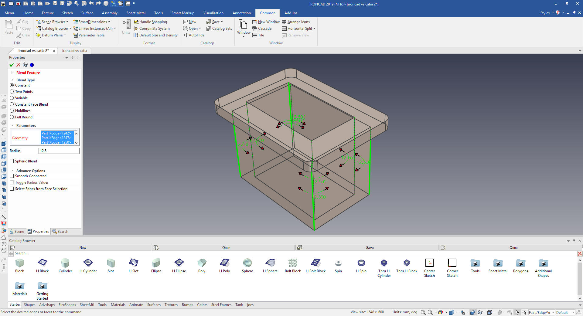
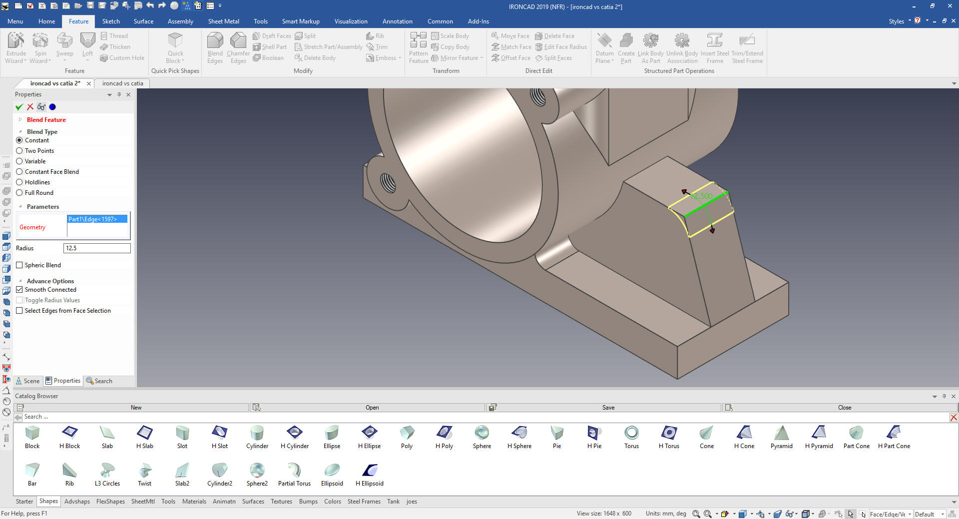
We then add
the blends. I have shown the hidden lines to make it easier to
create the blends. I just wanted to show this feature, I rarely use
it.
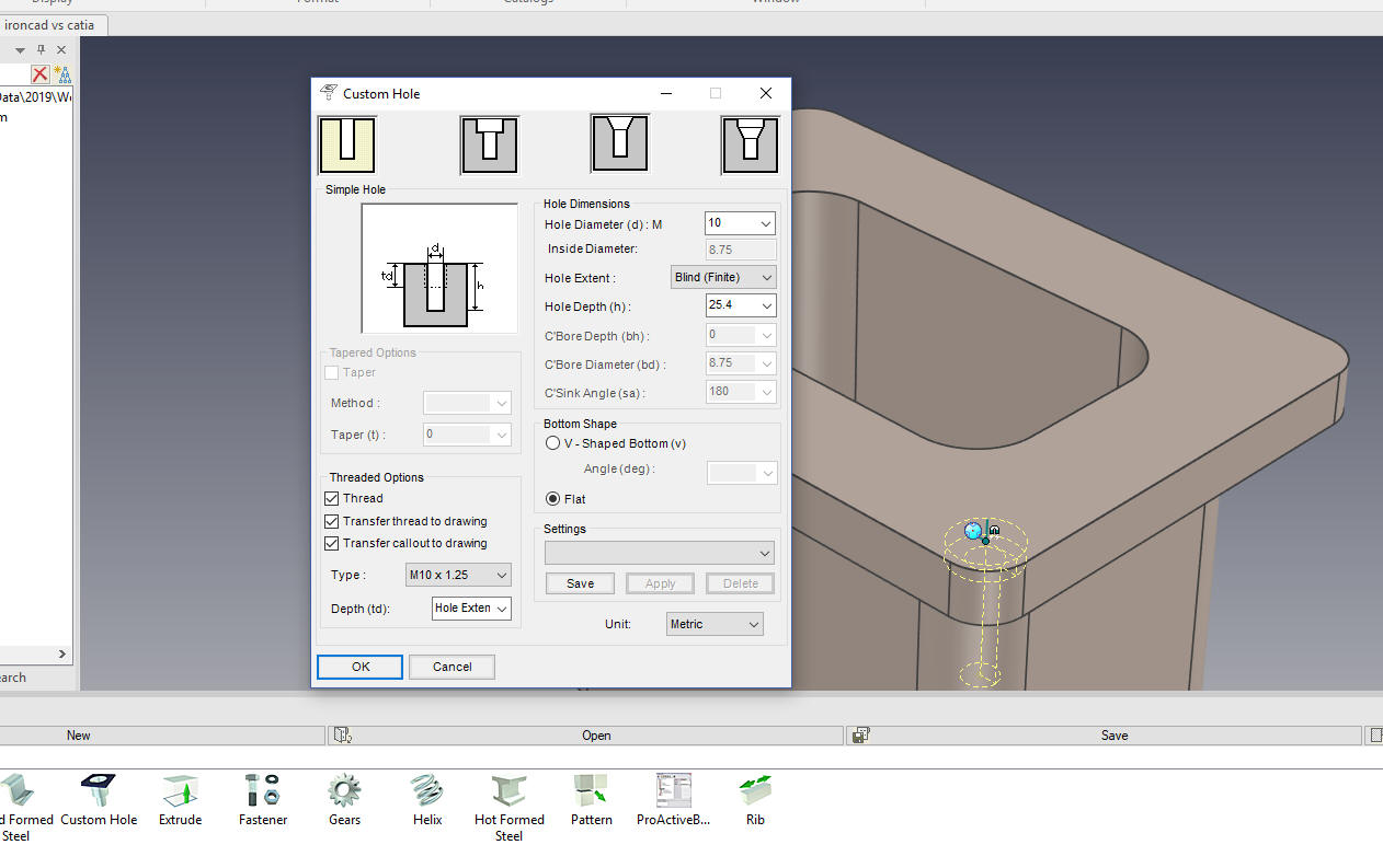
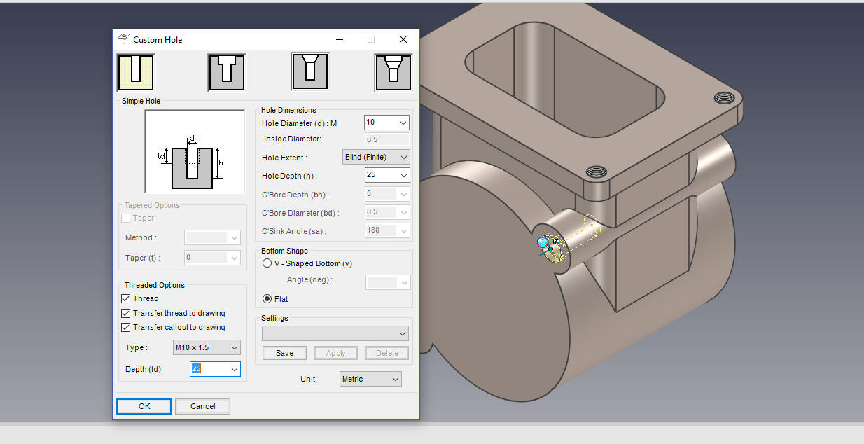
We now add the 10m threaded hole on the
top flange. We drag a hole from the custom hole option in the tool
catalog. We locate the first hole using the center of the blend. The
CATIA presenter has to create a reference point to locate the hole.
We have a couple of options we could use the Triball to link one by
one, we can pattern or we can Triball link two, then Triball link those two, which is
the process I will use.
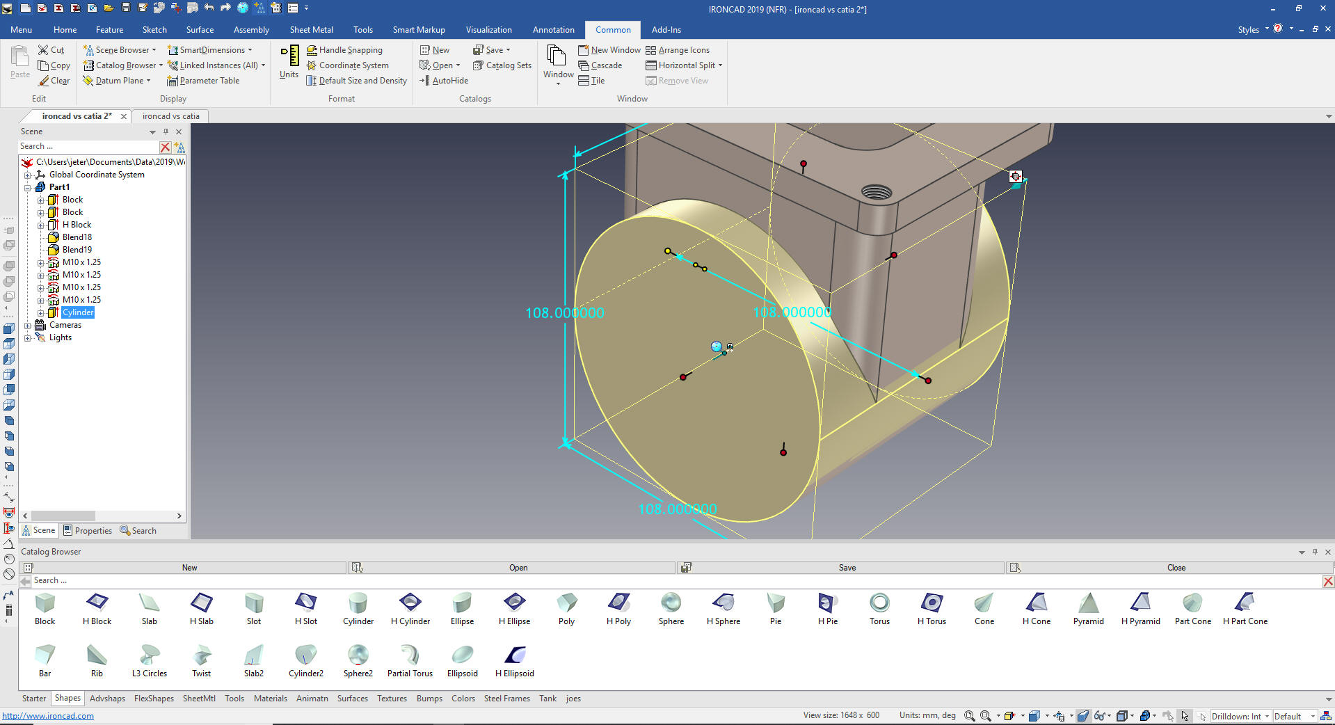
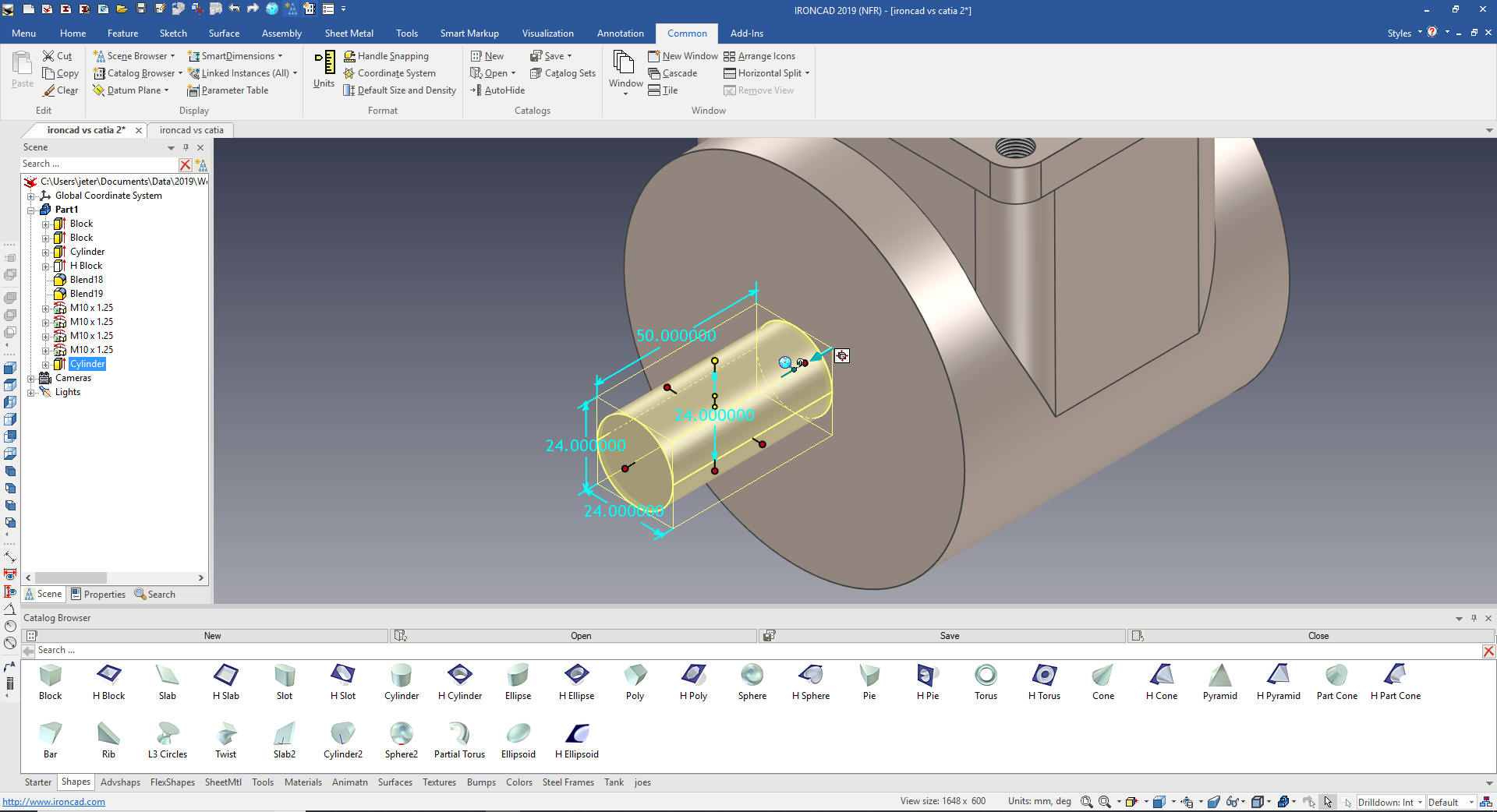
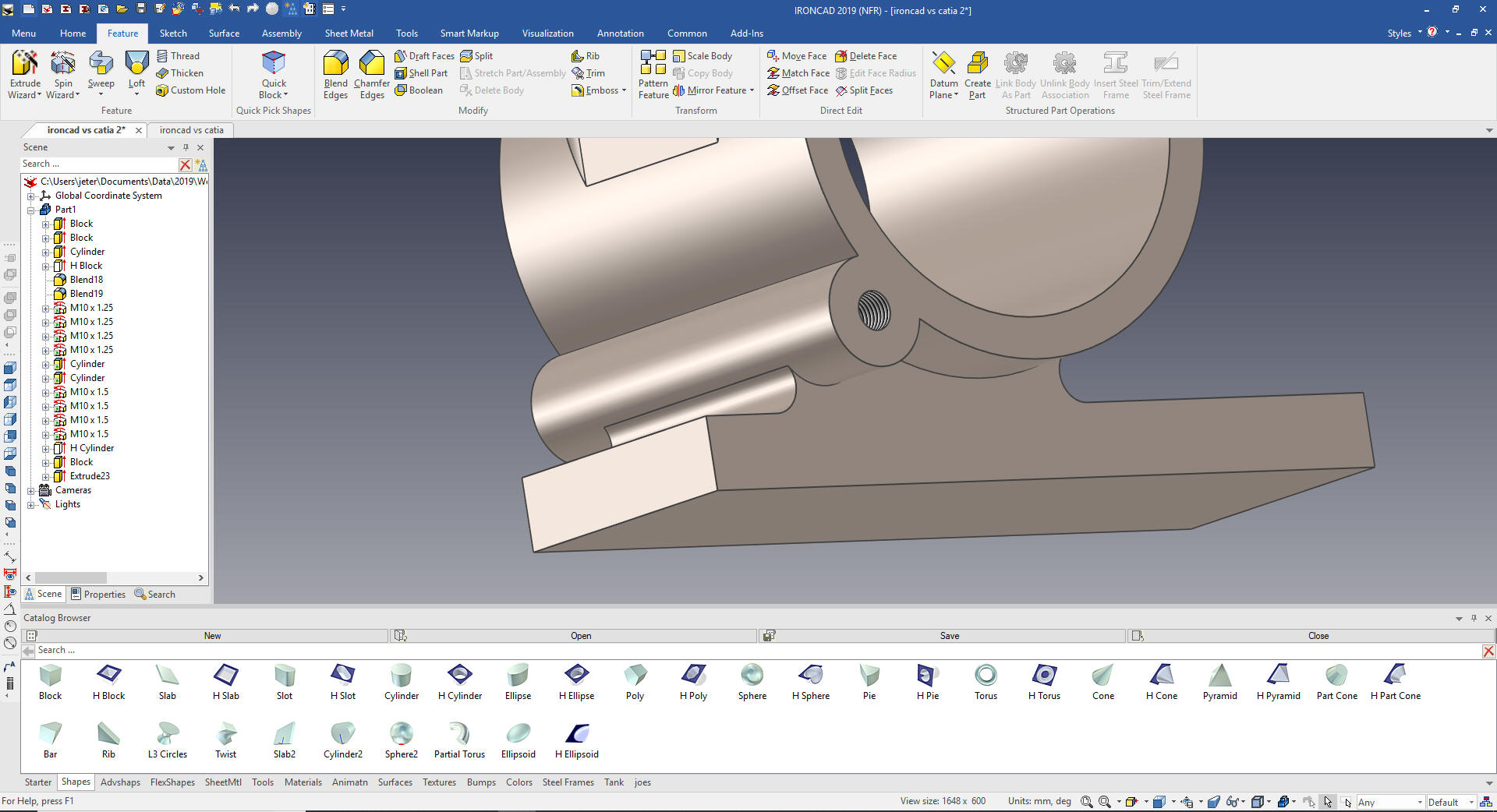
We drag and drop a cylinder on the lower
edge of the front face and size it.
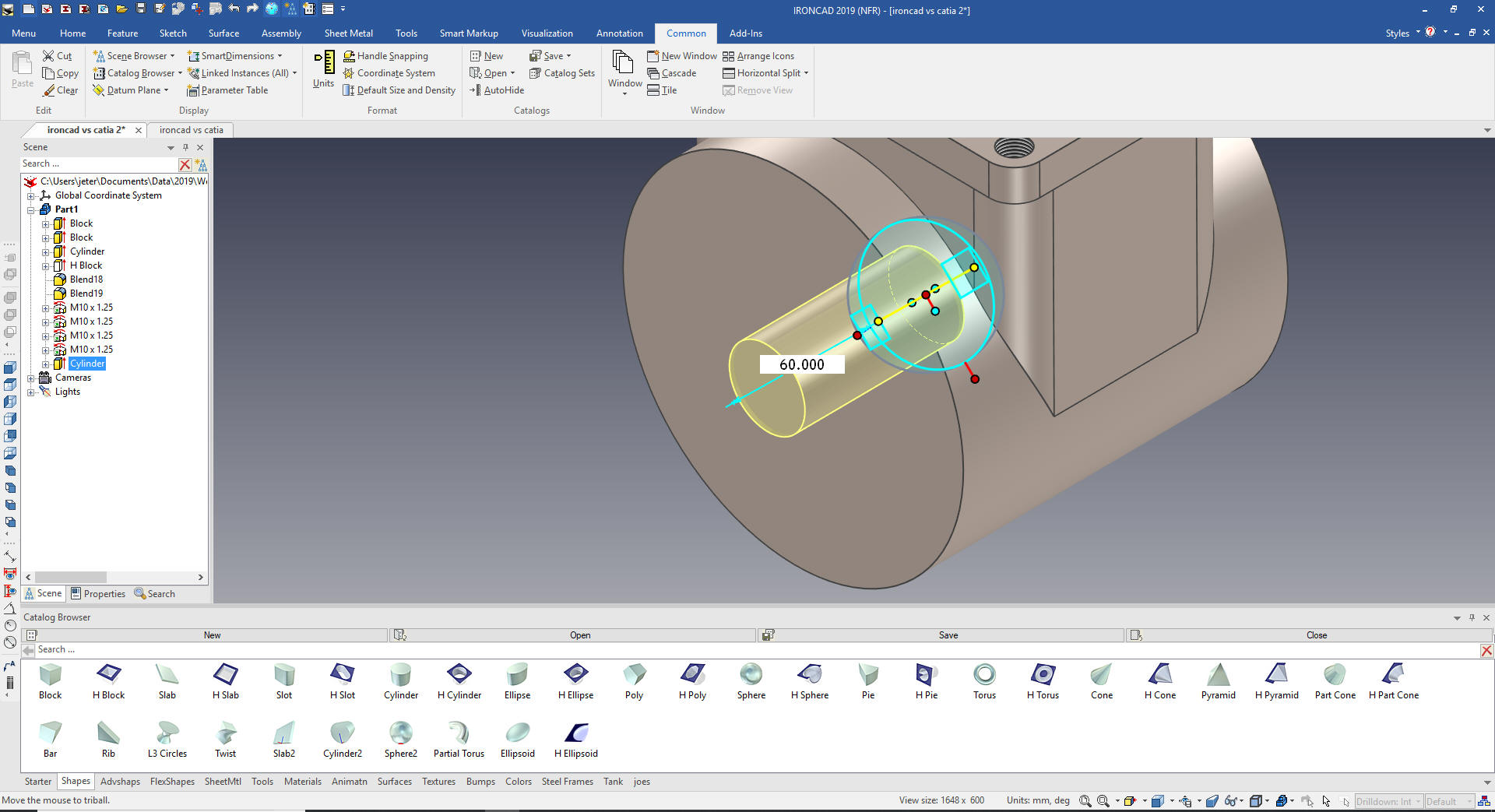
You can see that the hole does not go
through the cylinder. Take a look at the history and notice where
the cylinder is.
We just move the cylinder before the
hole and now the hole goes into the cylinder. This allows much more
flexibility in the design process.
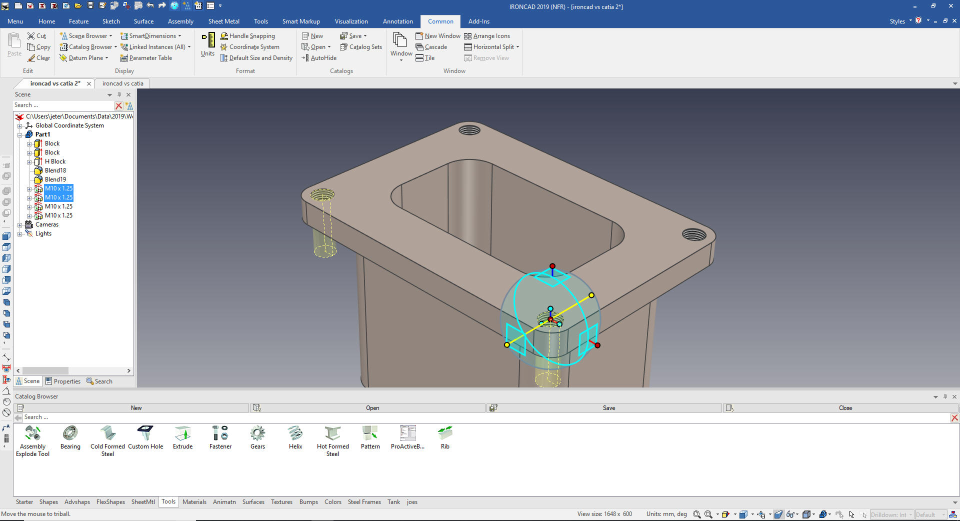
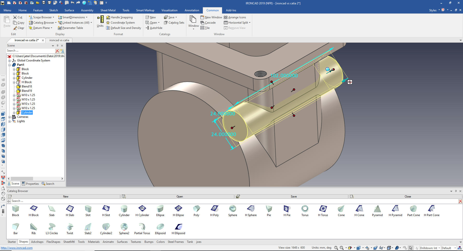
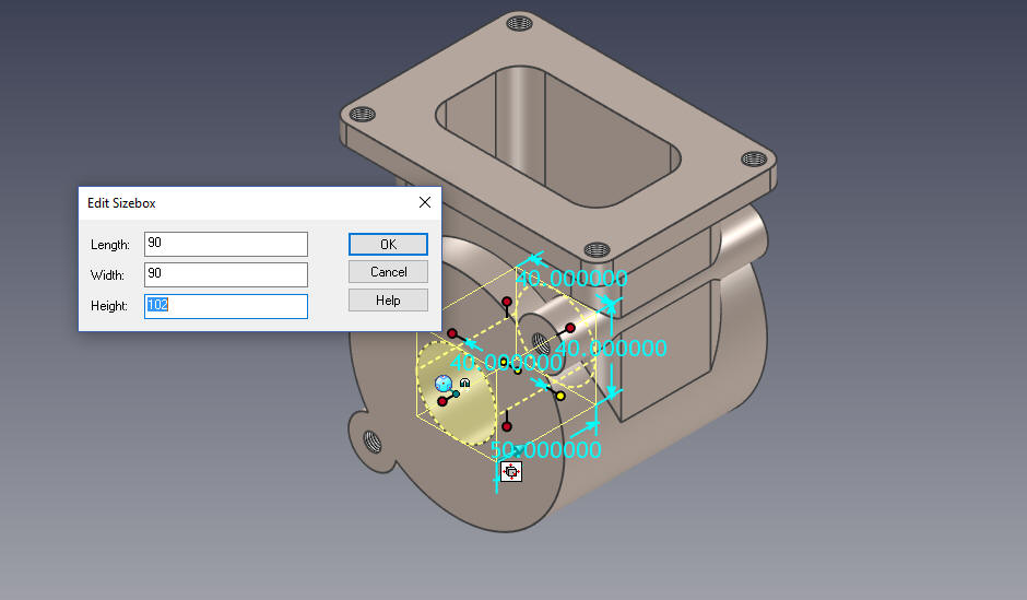
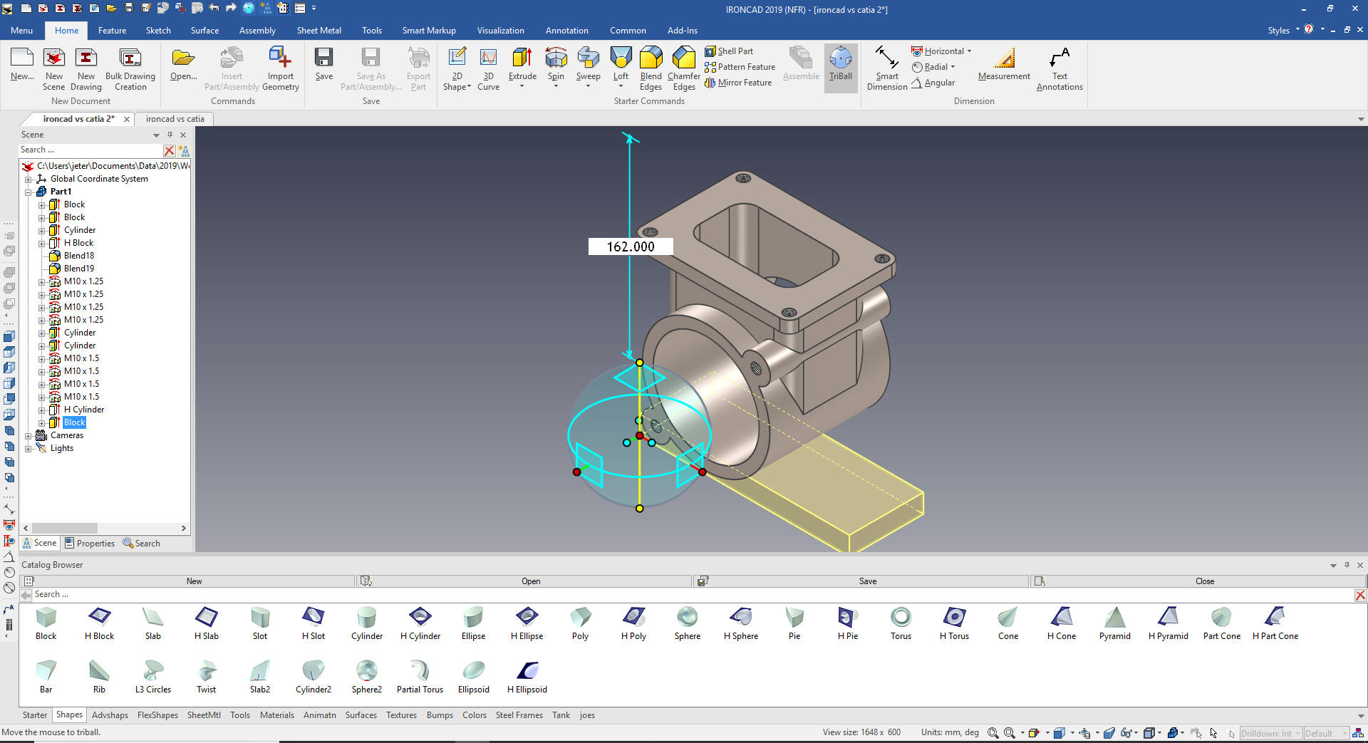
Now we added the first boss by dragging
and dropping a cylinder to the center of the large cylinder and we
size it.
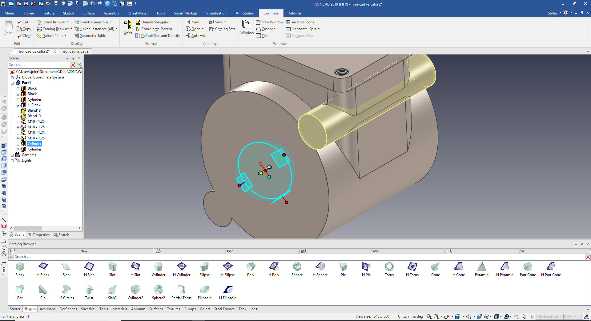
We use the
Triball to rotate the boss and pull to locate it.
We
size the boss by just pulling the handle, holding the shift button
to match the faces of the large cylinder
We
press the spacebar to move the Triball to the center of the large of
the cylinder and mirror link the boss.
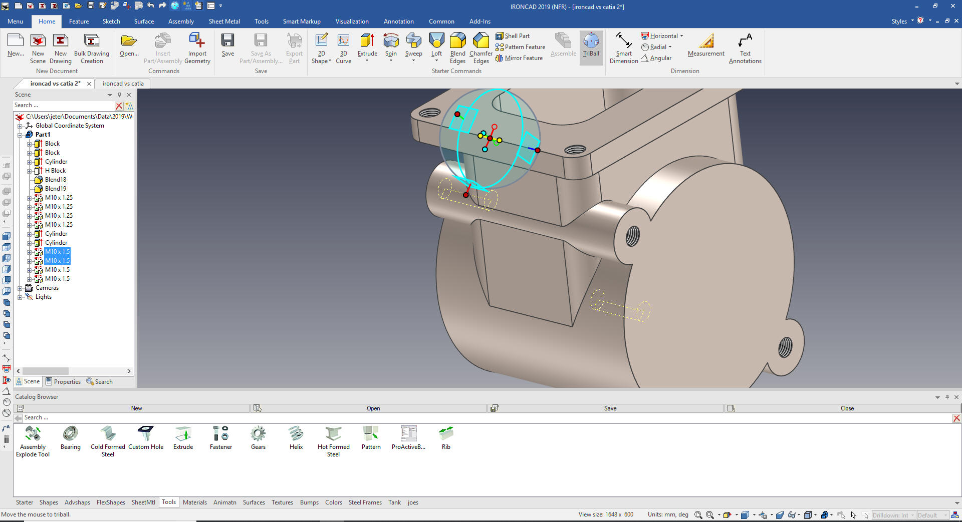
We add
the M10 hole in the boss.
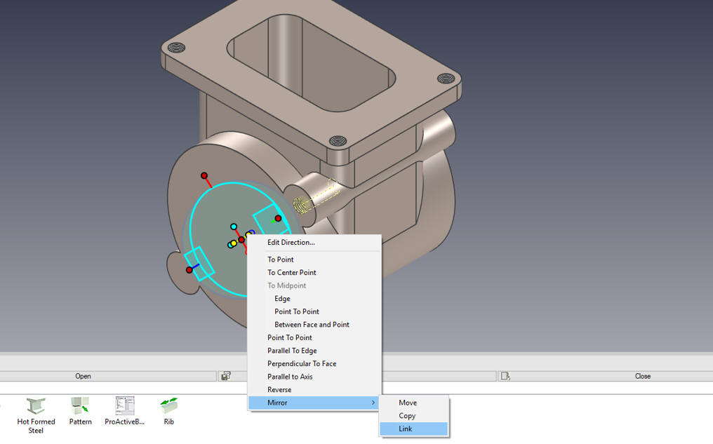
We
active the Triball, press the spacebar and move it to the center of
the large cylinder and select mirror link by right clicking the in
relative inside handle. The Triball is by far the most sophisticate
feature, part and assembly manipulator!
We select
both holes move the Triball to a middle position and mirror link.
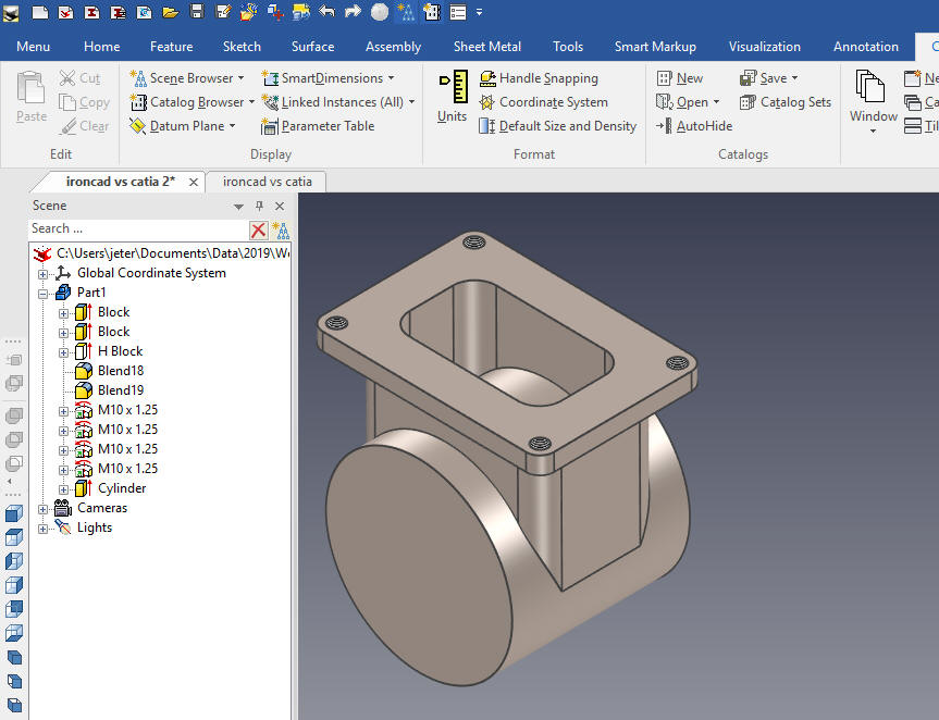
We
add the center hole by dragging and dropping a hole cylinder to the center of
the large cylinder and sized it.
When
you design with shapes a whole new world opens up to you. I drag and
drop a block on to the top flange of the model and size the base.
Now we move it into place with the Triball.
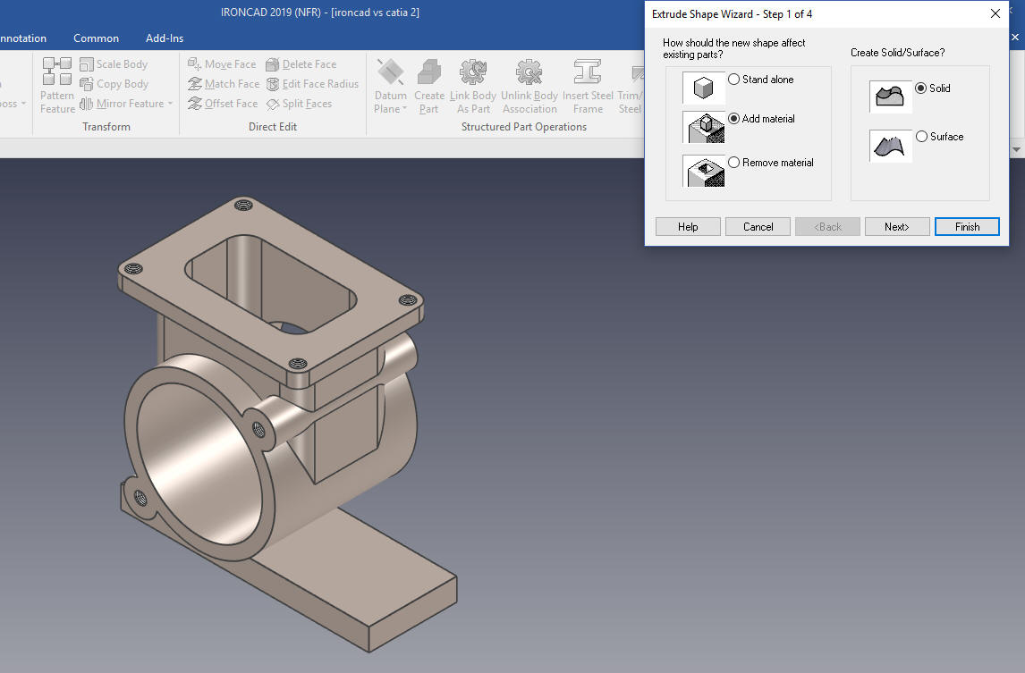
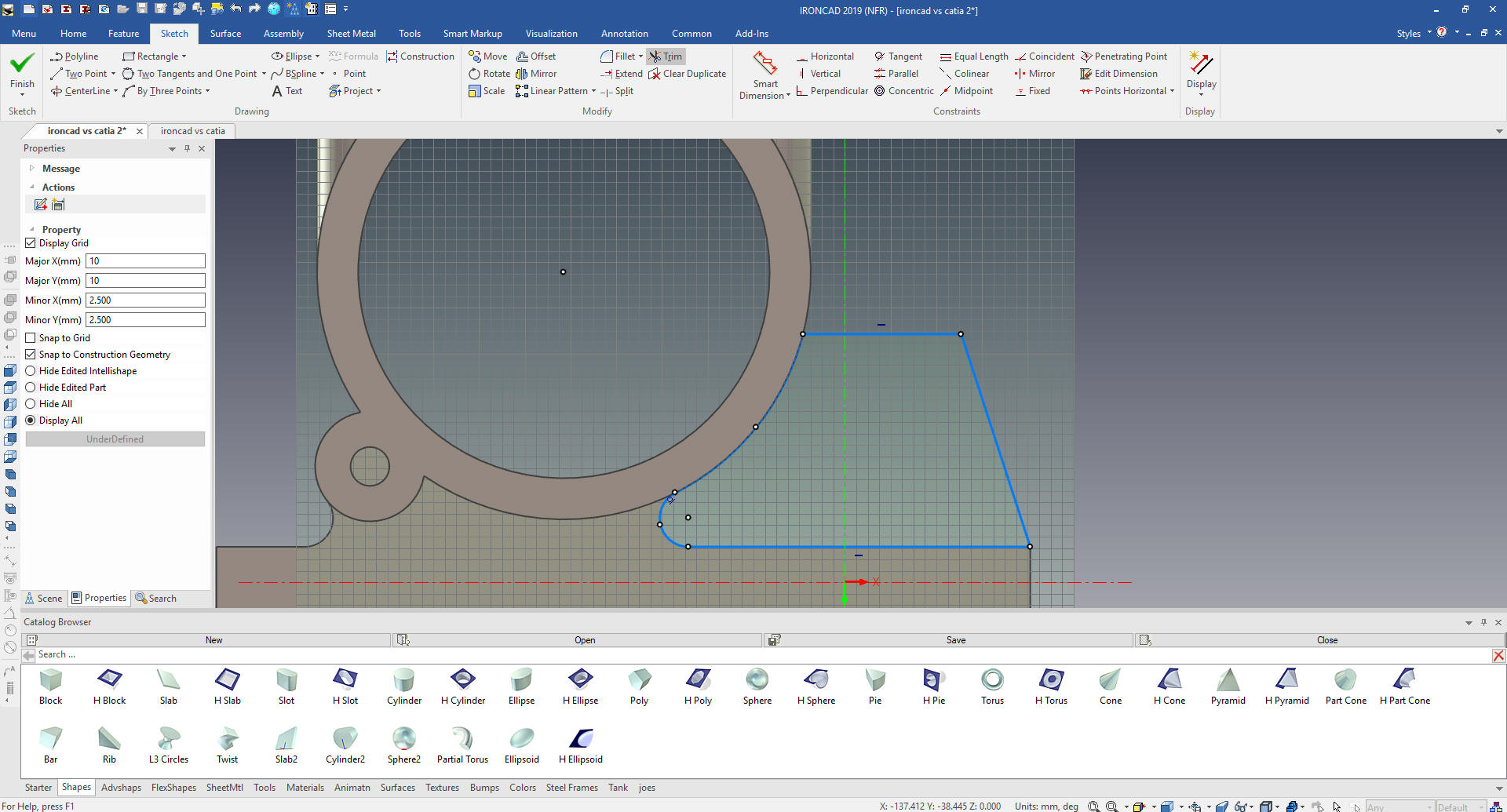
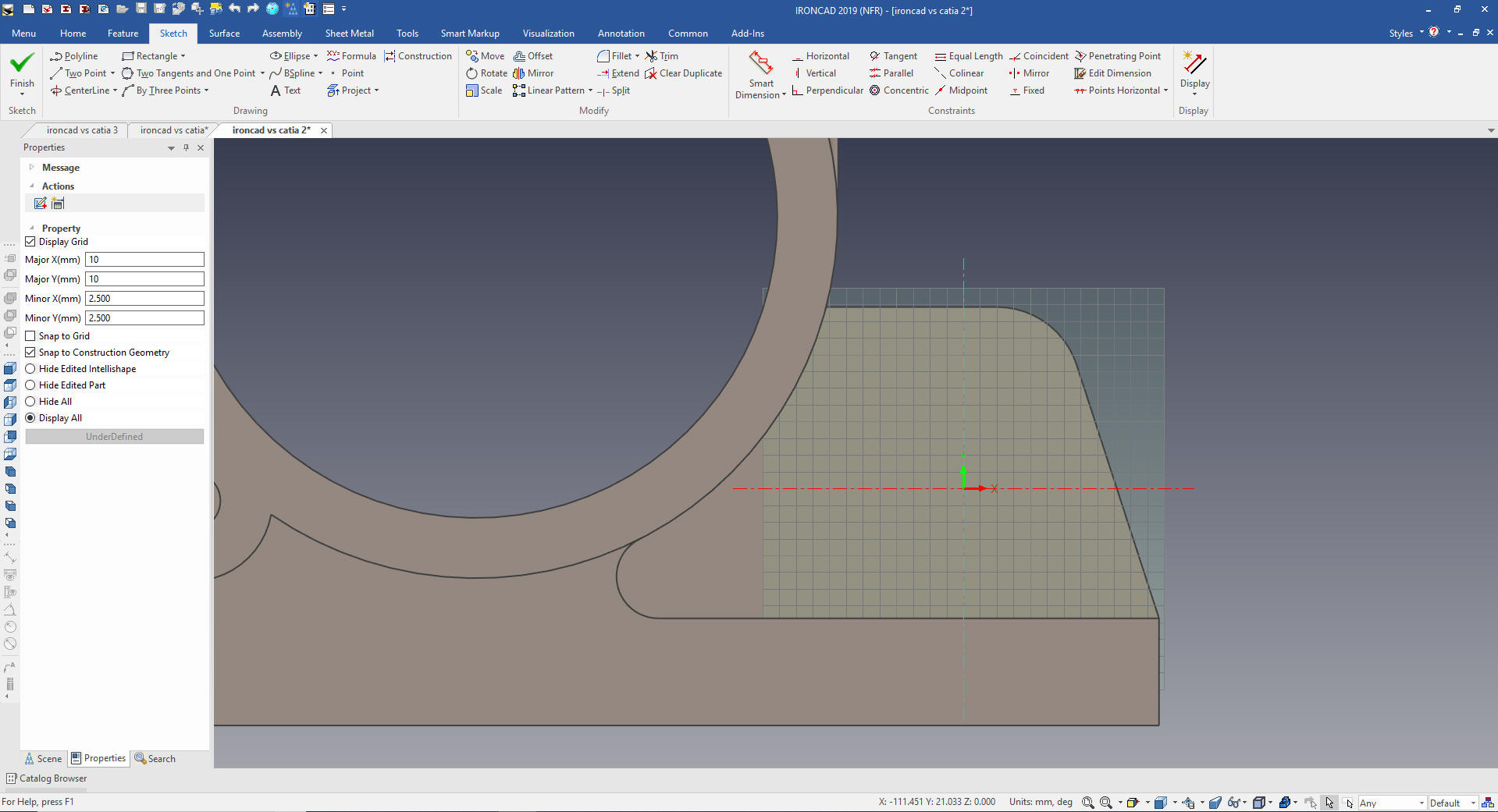
We select the Extrude Wizard and select the front face of the base
feature
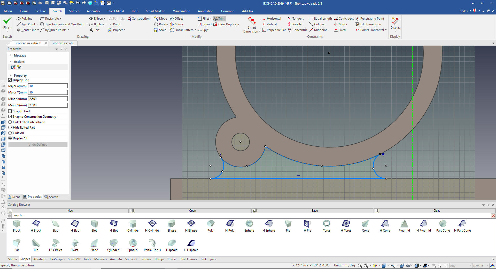
We
create the sketch by projecting the relative edges and putting in 2
tangent and raduis circles and trimming. No constraints.
We
select okay an our extrusion is complete. The Extrude Wizard is used
through out the design process. IronCAD is a single mode design
environment and the Extruded Wizard is indispensible for in context
design creating features for mating parts.
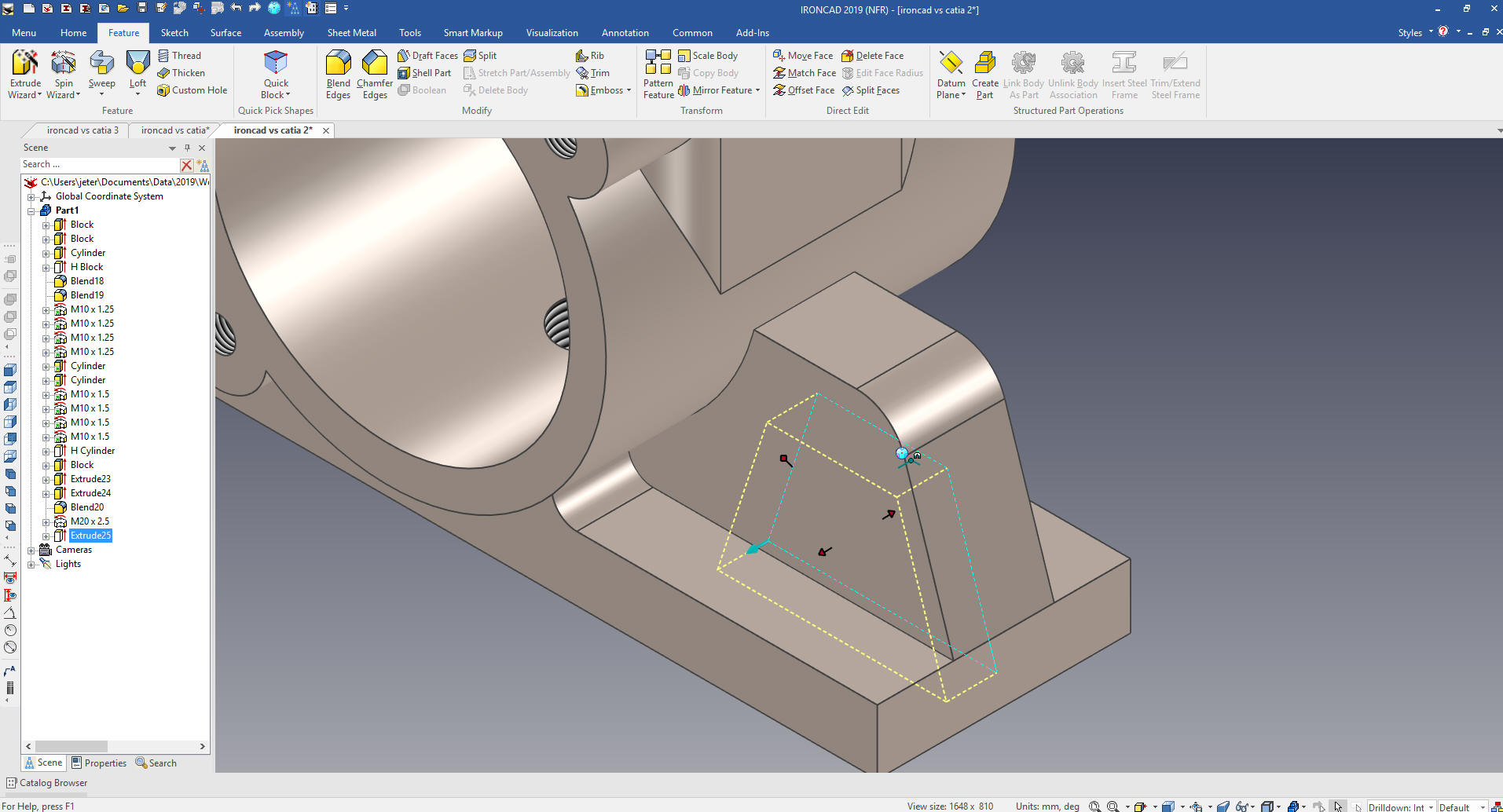
Now
for the rib. Again we use the Extrude Wizard and set to add, we
select the front face of the base feature again and project the
relative edges create the two lines. Notice I do not include the
blend. Again, no constraints.
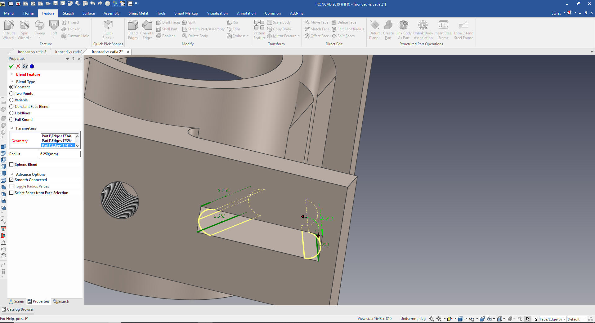
We
now put in the blend.
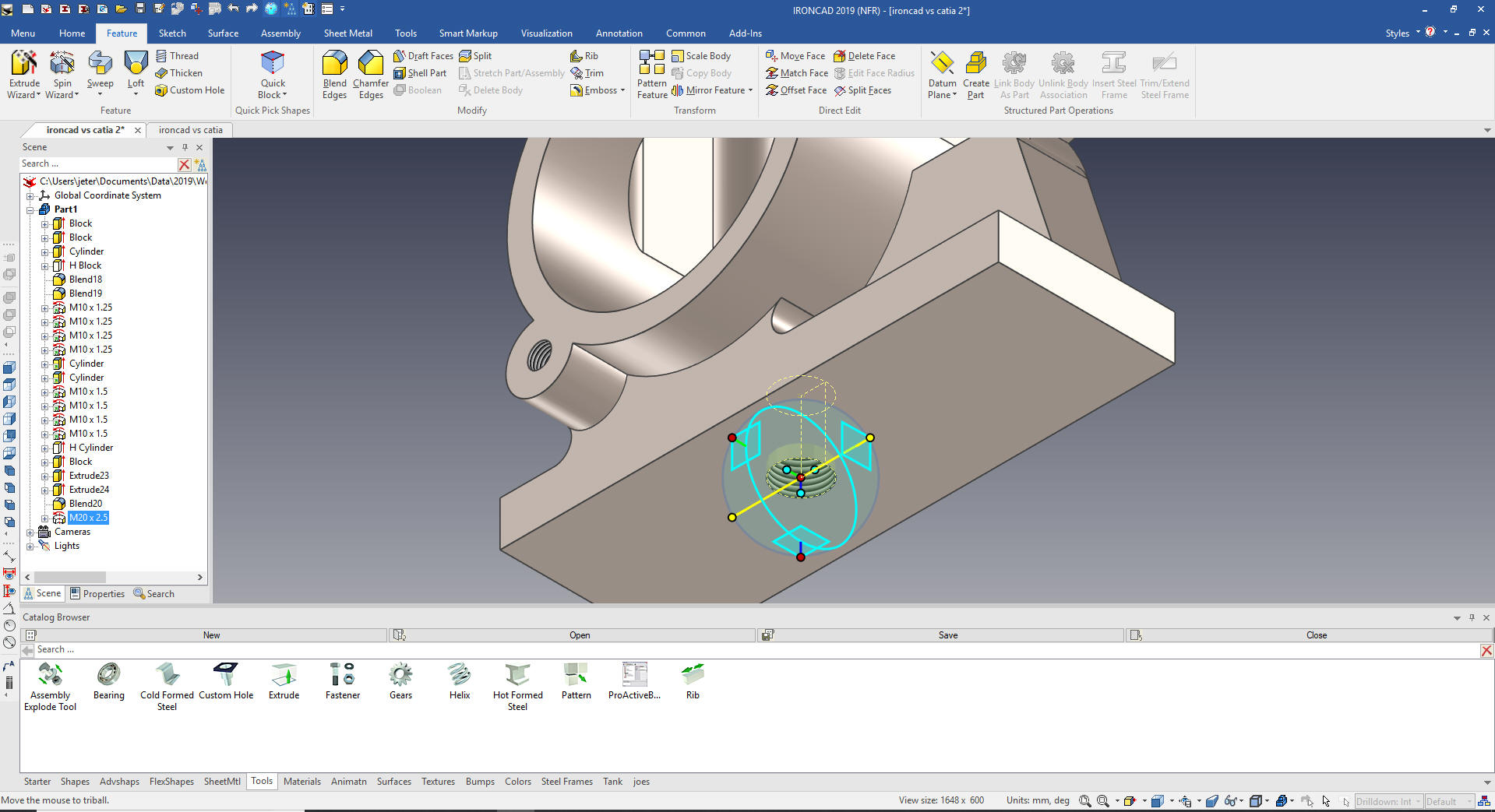
We
drag and drop a Custom Hole from the Tool Catalog to the mid-point
on the base feature and locate it with the Triball.
We
now add the small slot on the bottom. Using the Extrude Wizzard we
create a sketch and set it to remove. We project the relative
features offset, mirror, extend and trim as necessary. Notice for
the 3rd time no constrains.
We
select okay and locate the feature.
Add
the blends.
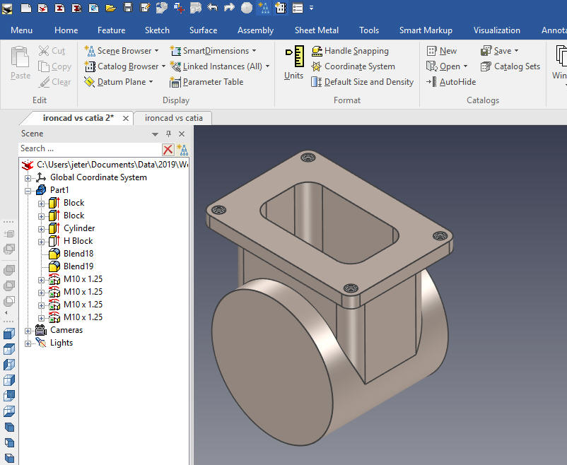
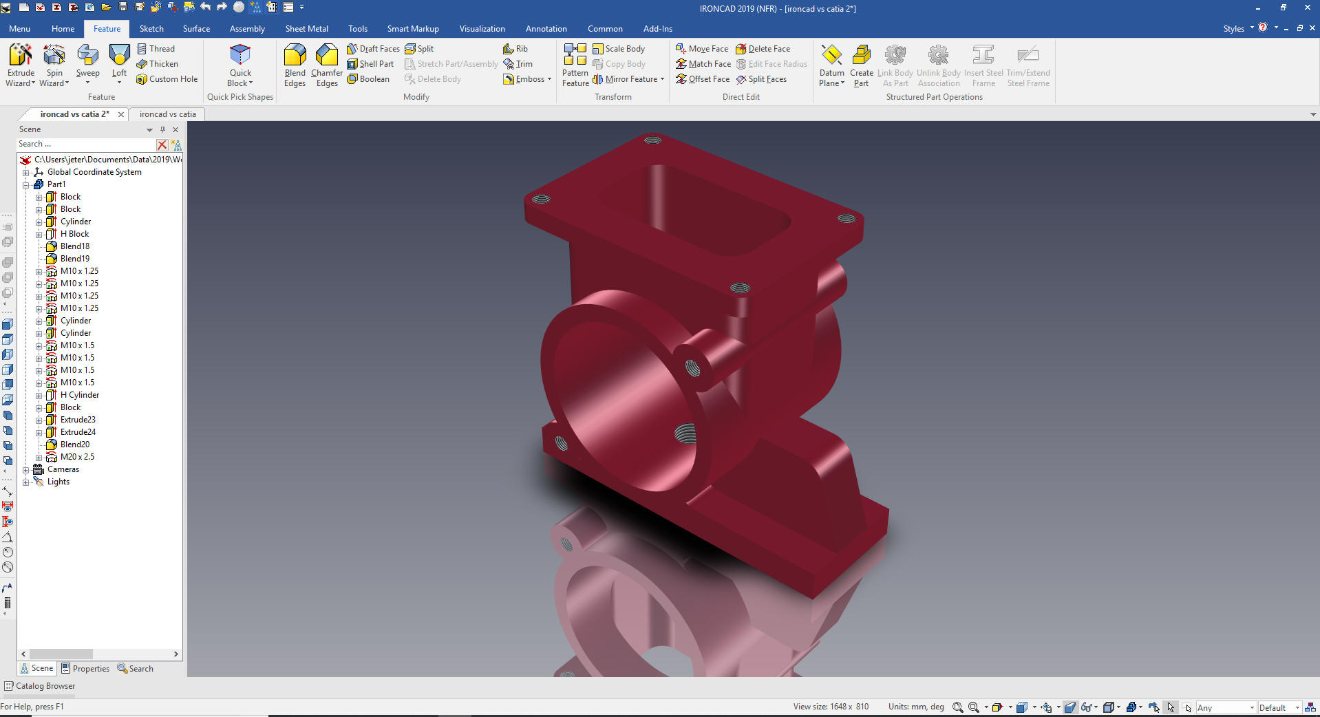
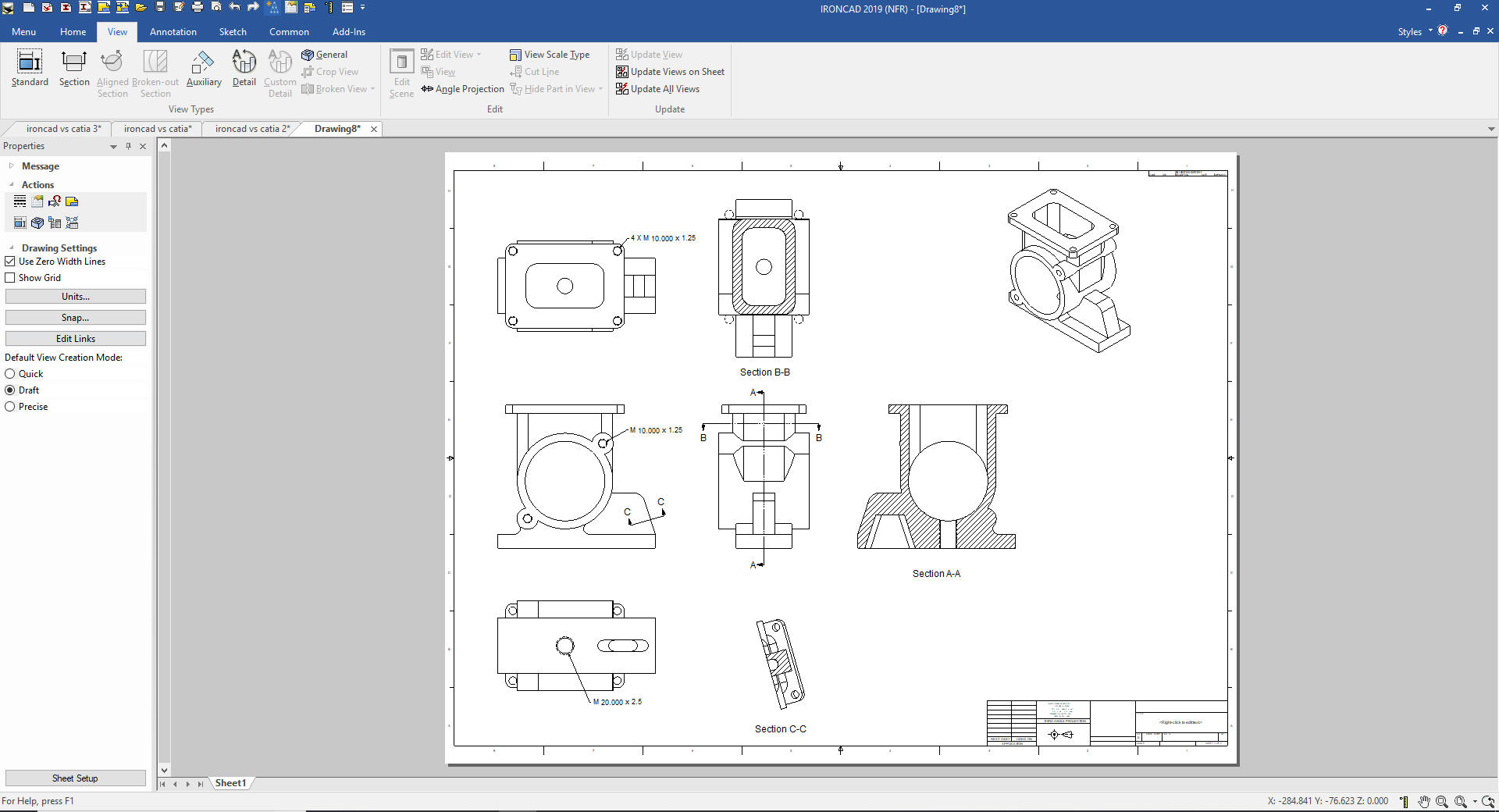
Add a
few effects and we are done with a fun part. I have included the AID
(drawing) so you can practice with your own CAD system.
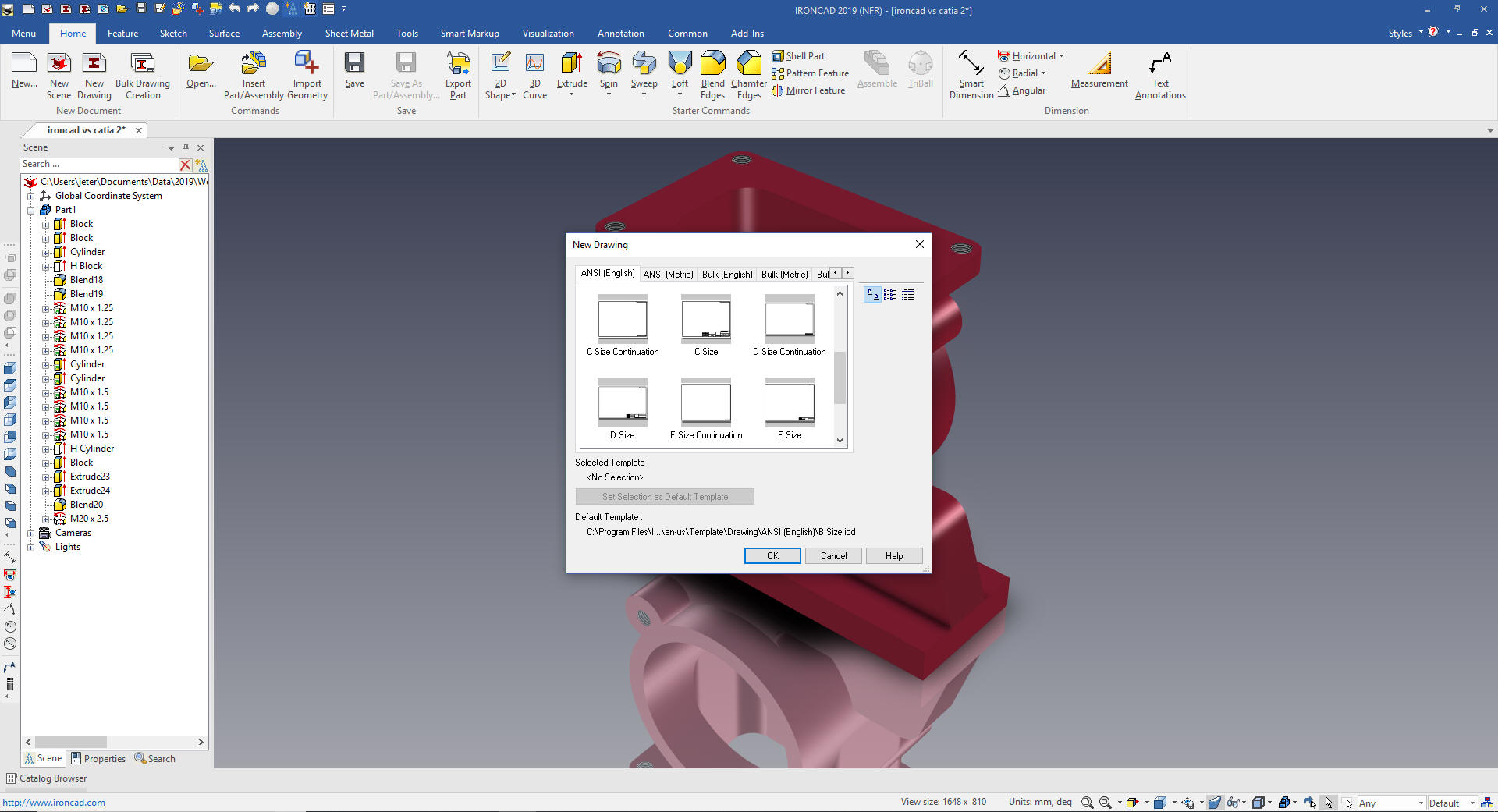
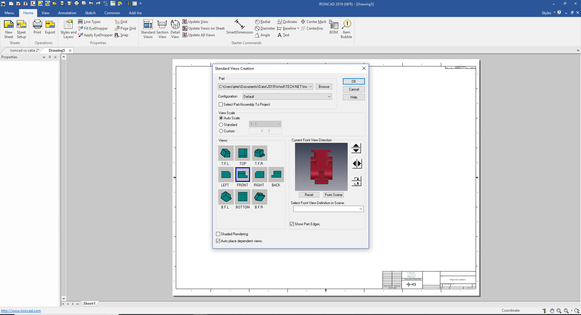
Since
we didn't have a drawing we will now create the AID. IronCAD has a
separate documentation module. Since IronCAD is a Single Model
Design Environment we can have complete projects in two files.
But if you have the job of converting drawings to 3D you have to
create a drawing to check to see it the model is correct.
It is
very important that you look into how you or your engineers are
creating the parts. Streamline Sketching and Feature Based Modeling
is easy to learn and implement. It, alone, will increase
productivity 10X. Now, IronCAD with its unique integrated
history/direct edit functionality can increase your productivity
another 5X or more with changes! Again, time is money in
engineering.
More on Streamline Sketching and Feature
Based Modeling.
To experience this increased level of productivity, please download
IronCAD for a 30 day evaluation. Legacy data is no problem, IronCAD
can read the native files of all of the popular programs. IronCAD is
a great replacement for the subscription only Autodesk and PTC
products.
Give me a call if you have any
questions. I can set up a skype or gotomeeting to show this part
or answer any of your questions on the operation of IronCAD. It
truly is the very best conceptual 3D CAD system.