IRONCAD vs CATIA Lesson 2 3D Modeling Techniques Defined Streamlined Sketching/Feature Based Modeling
The modeling technique is
hugely responsible for the level of productivity. Those of you that
are only trained in the constrained sketching world of the major CAD
systems
are truly limited by not using the freedom of Streamlined Sketching
and Feature Based Design,
that is available in even the most Pro/e-ish of CAD systems. If you
or your
designers are designing in these very unproductive and time
consuming processes it might be time to review your standard design
processes. Don't have any do you?
These
lessons started out as
product comparisons, but quickly turned into a study in 3D modeling
techniques.
When I introduce IronCAD's very
flexible design paradigm I have a hard time to get the Pro/e clone
users, like Solidworks and other programs to understand the drag and
drop design paradigm.
Download
IronCAD/Inovate and take
the one day and 17 lesson course. I get rave reviews from my new
customers. Give it a try, this is a fully functional 30 day
evaluation with all of the native translators so you have access to
your legacy engineering information.
IronCAD Self-Pace Training Course I saw the
following CATIA YouTube tutorial and thought I would give it a
try on IronCAD. I have to tell you it is almost tortuous to watch
the CATIA presenter. CATIA is a constrained sketched based
system as are Fusion 360, NX, Inventor, Solidworks and Creo. This modeling paradigm is used throughout
the industry causing millions of wasted hours.
I have to say the CATIA
presenter struggle with such a simple part. I cannot imagine the
wasted time CATIA is creating for companies like Boeing, Bombardier,
Airbus, Gulfstream, Chrysler and so many more.
While creating 3D models from a drawing is the very best
way to learn 3D CAD and maybe some design techniques is does not
expose the designer to the design flexibility necessary in product
design. IronCAD is all top down due to the single model environment.
Creating mating parts is a cruise. But effective modeling is just one aspect of a
well designed productive 3D CAD system.
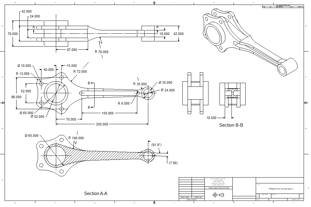
The AID (drawing) is at the
end of this article if you would like to try this lesson. IronCAD vs CATIA
I would do a
video, but I really am not good at it. So I will show you step by
step. I will try and get ZW3D support to create one. They are
very good.
I usually create the part before I watch
the Video, so as to not taint my process, but this time there was no
drawing so I had to suffer through this presentation getting the
dimensions. Of course,
there are a multitude of ways to create a model. There is no right
way, just more productive ways. But from what I have seen from these
very complicated processes done by the CATIA presenter, it is not
just limited by the 3D CAD system.
I have to say this is
incredibly simple. But the CATIA presenter has been
indoctrinated into these designs techniques. It started with Pro/e (Creo)
and has been the way the sketch, constrain and assemble. The
Solidworks clones are costing the industry millions, if not billions,
in lost productivity.
I actually created this part by
studying the CATIA presenters video since there was no drawing. It
was a bit torturous. But I finally got it modeled and then created a
fully detailed
AID (drawing) and did it again to optimize the modeling process. I had to refined it to a bit better designed
model. You can see by the AID it is a very simple part as compared
to the poor CATIA user. Sadly, we can model anything. But I believe
all CAD engineers should understand basic machining to be a good
designer and modeler to provide inspectable documentation.
Here is IronCAD. We will set the units
to millimeters.
IronCAD has two sketching features
The Standalone that allows you to sketch and save the sketch at
any level of completion, this is used when creating a complex sketch
or when importing .dxf or .dwg to
use to make 2D into 3D.
The sketch wizards instantly
turn extrusions and spins into a solid model so the sketch has to be
correct. You use this when
creating new features or part by projecting mating edges.
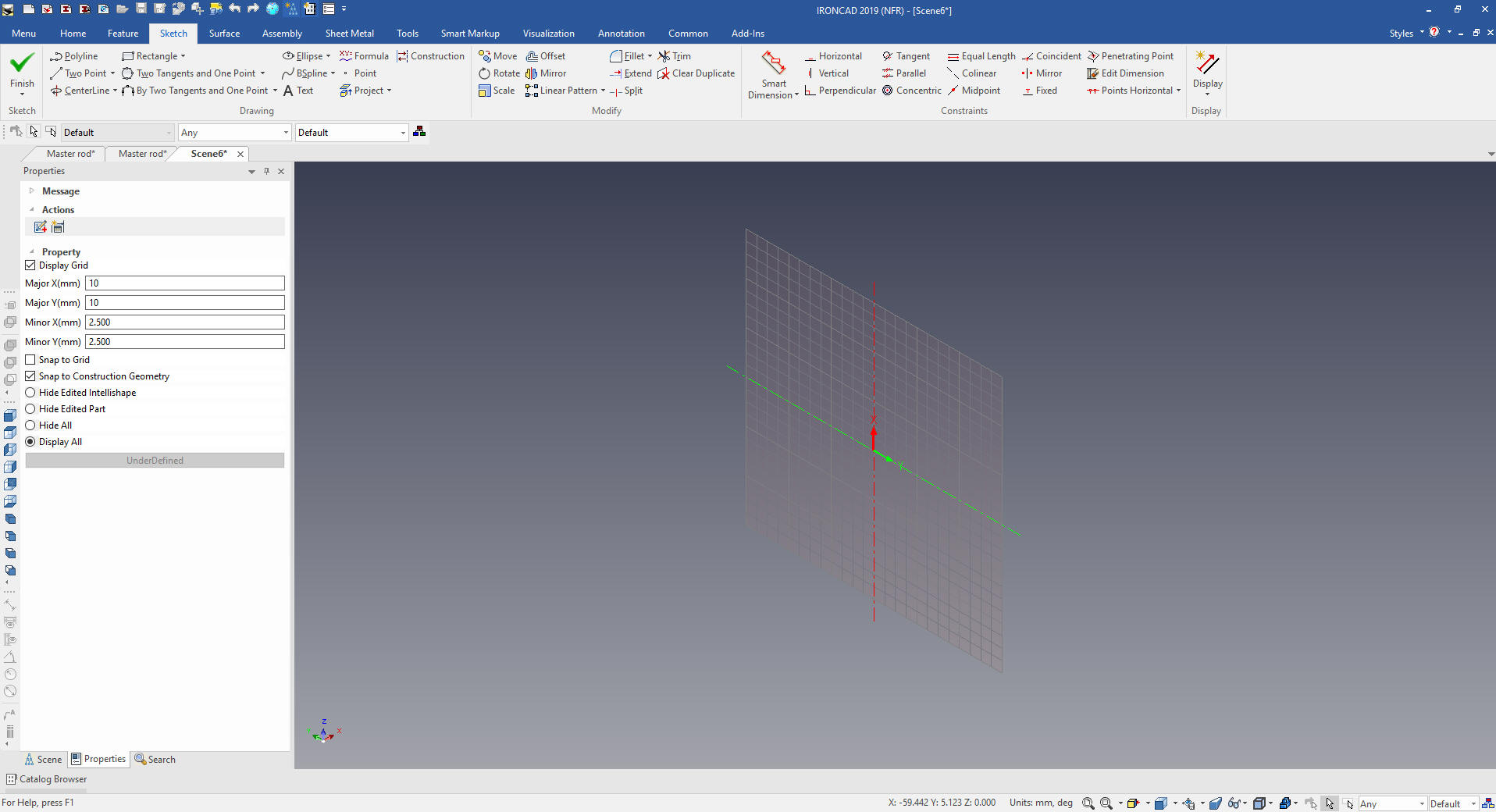
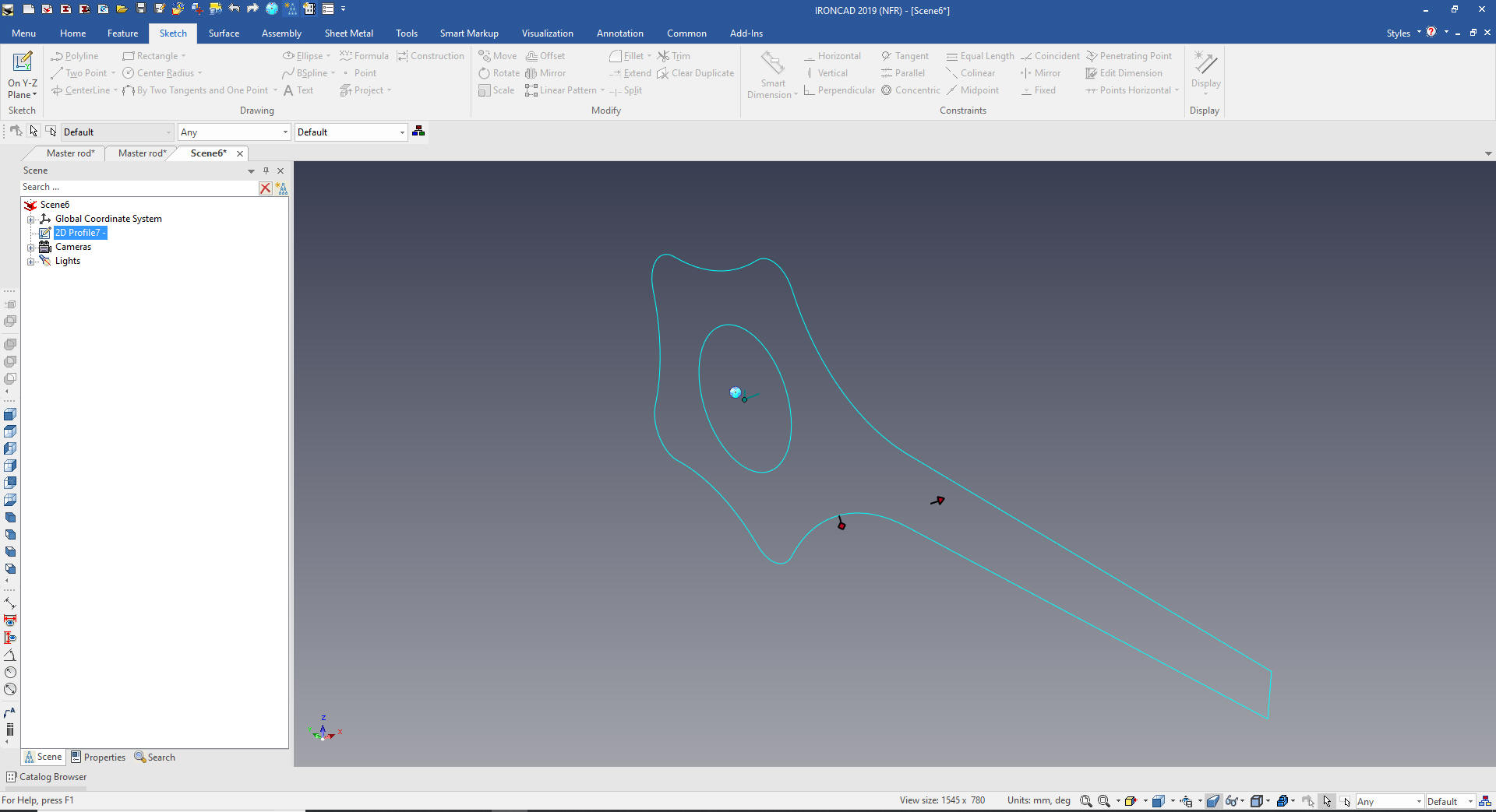
We will start by creating a standalone sketch on the YZ plane.
We will look into the plane and put in a few lines to use for
reference.
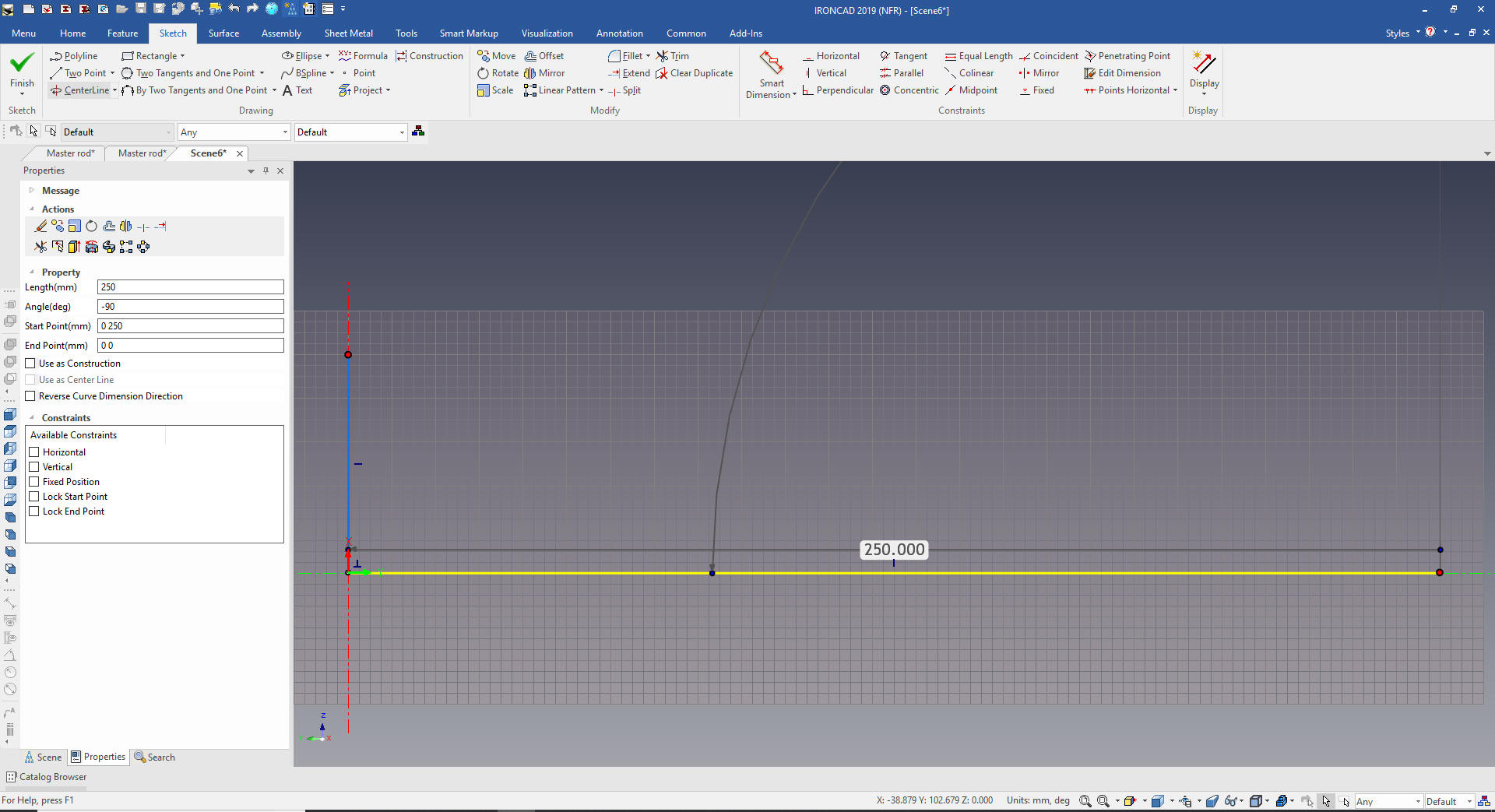
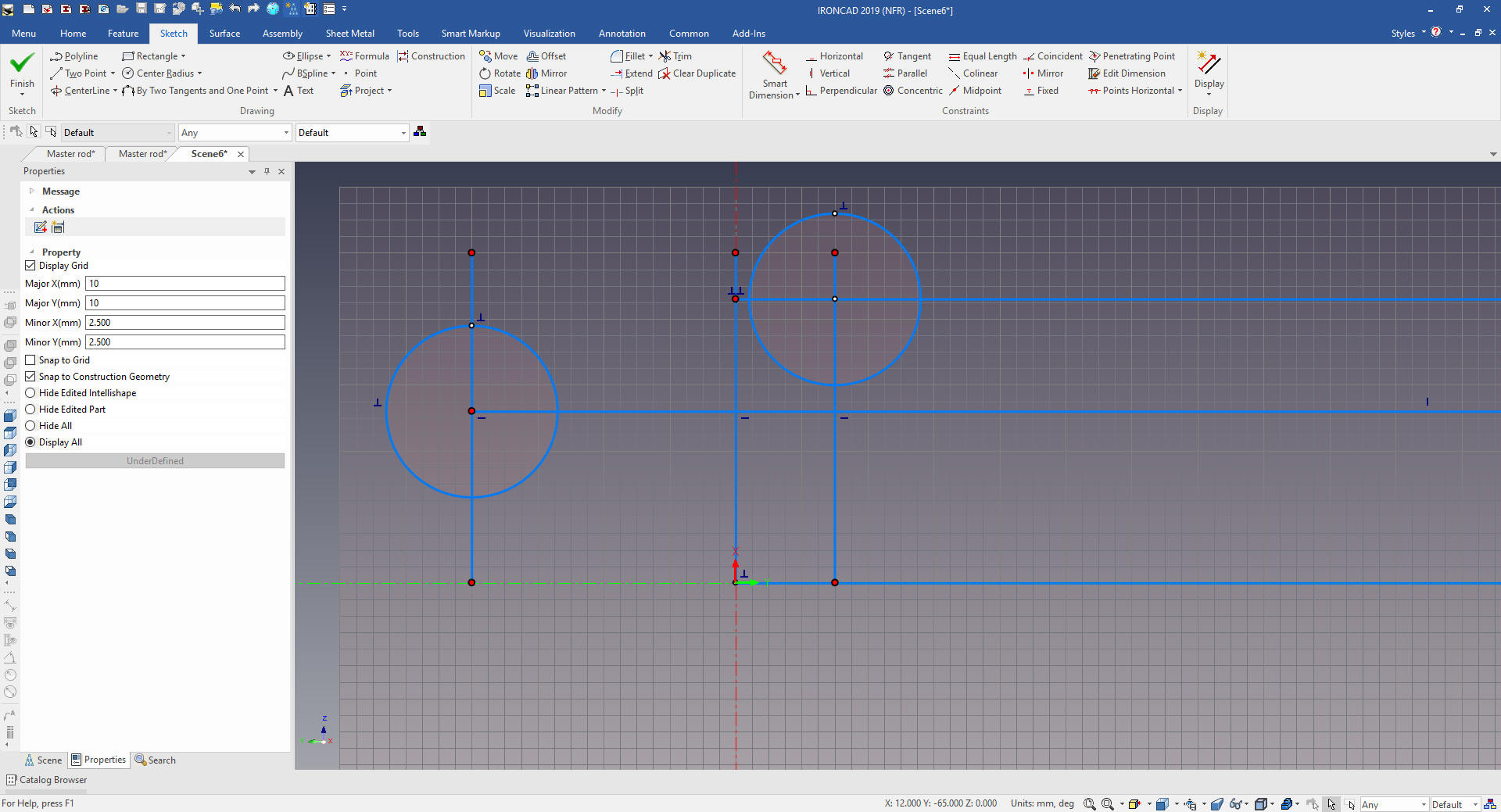
We
offset copy some lines to locate our first circles.
I
delete the reference graphics.
The Catia fellow locks an arc
to locate the angled edges. Now this is fine for a CAD jockey I have
to think about how this part is going to be documented.
Do I
will defined this edge by offsetting two lines and set their length.
We connect the ends and extend the line. We create two arc with two
tangent and a point.
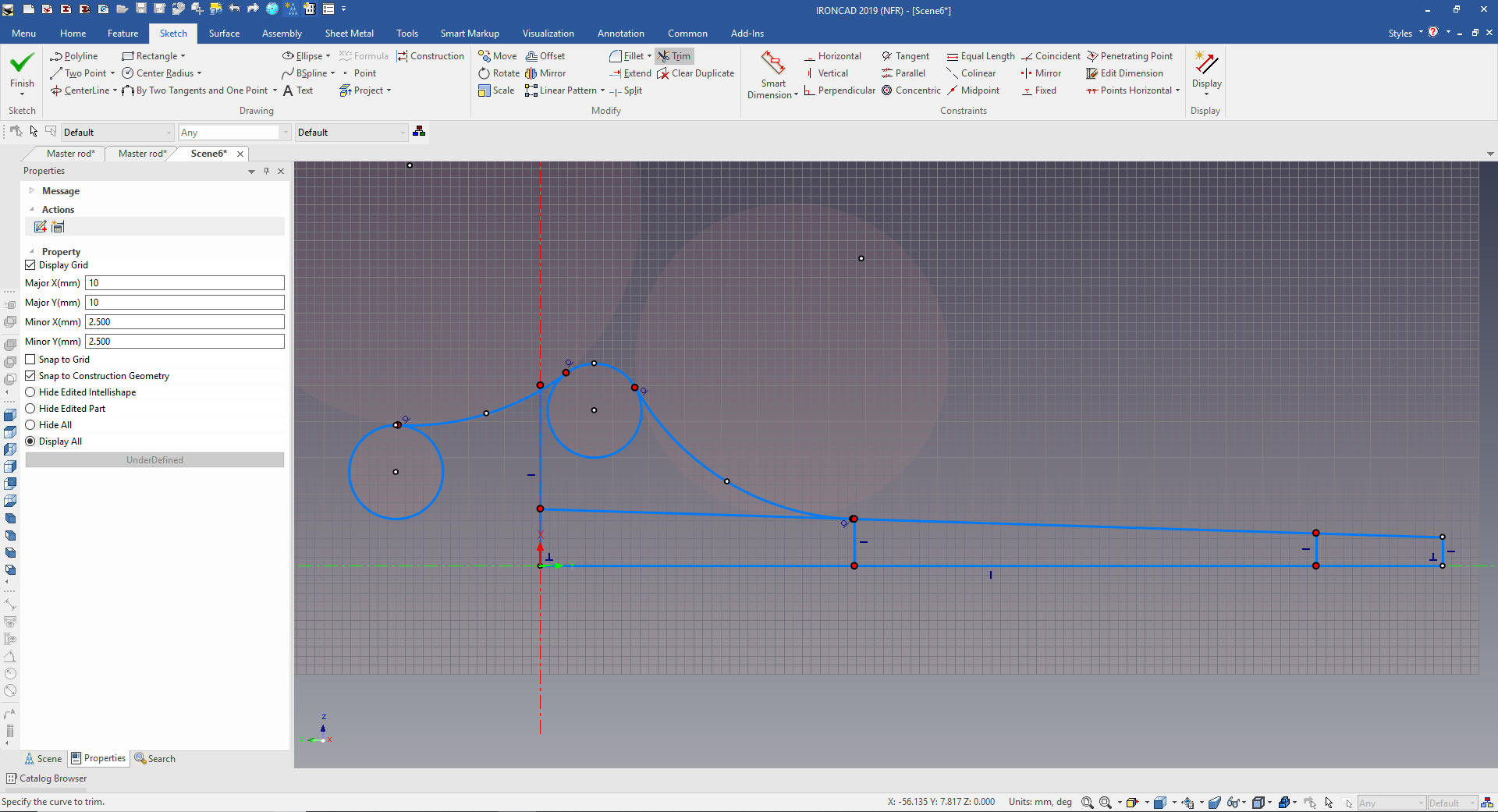
We
clean up the extraneous graphic by deleting or trim/extend. We
select the graphics to mirror. I don't understand why the Catia
fellow only created half and then mirrored the solid. I feel in this
case it was easier to create the complete sketch there are so few
entities.
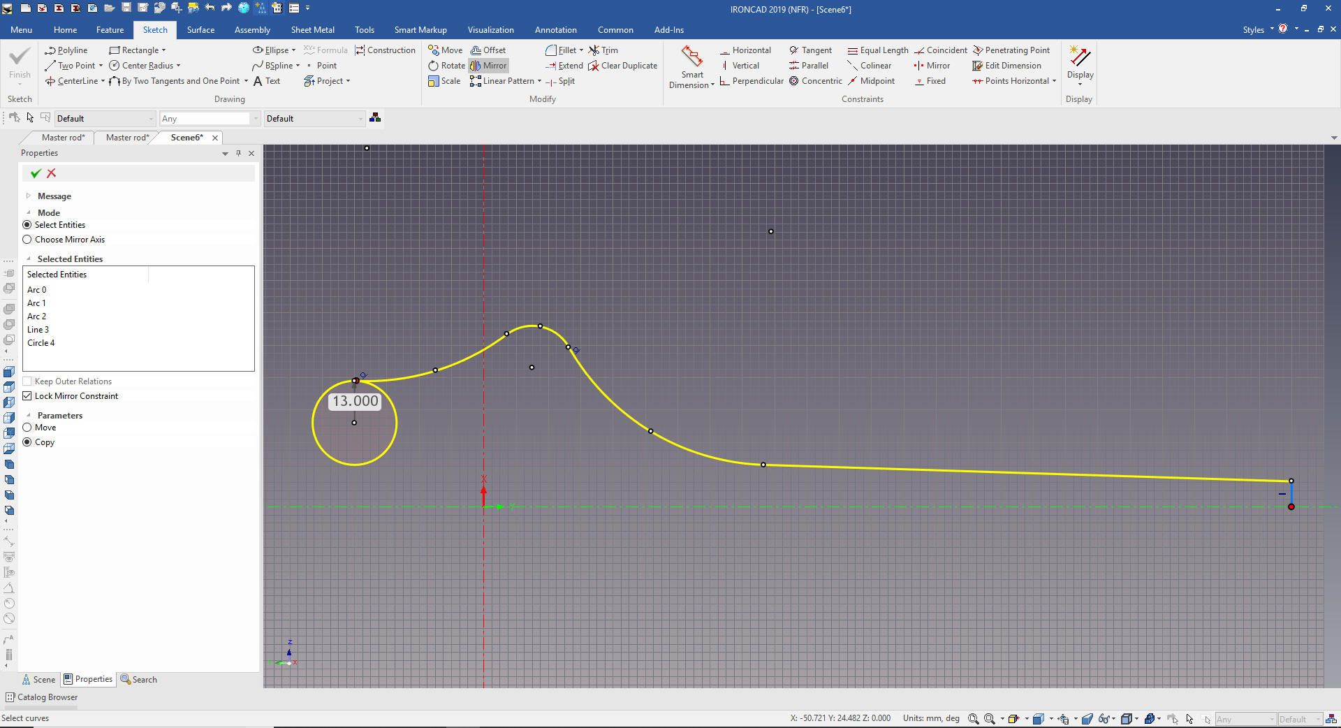
We
mirror and add the last arc, trim and extend. If you look at the
CATIA presenters end arc it was not tangent. Even when we are doing
examples we should focus on correct part design.
I add the hole in the
middle for reference later. The difference between a CAD jockey and a designer is the
consideration of the documentation.
We
are done with the sketch.
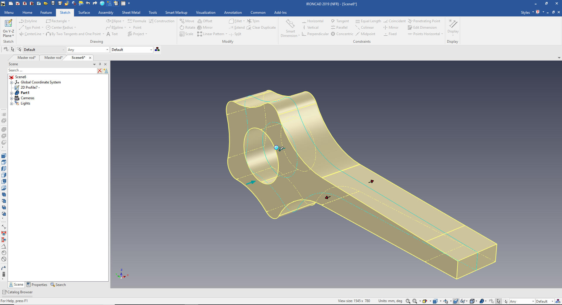
We
now select the sketch and create extrude to the 42m.
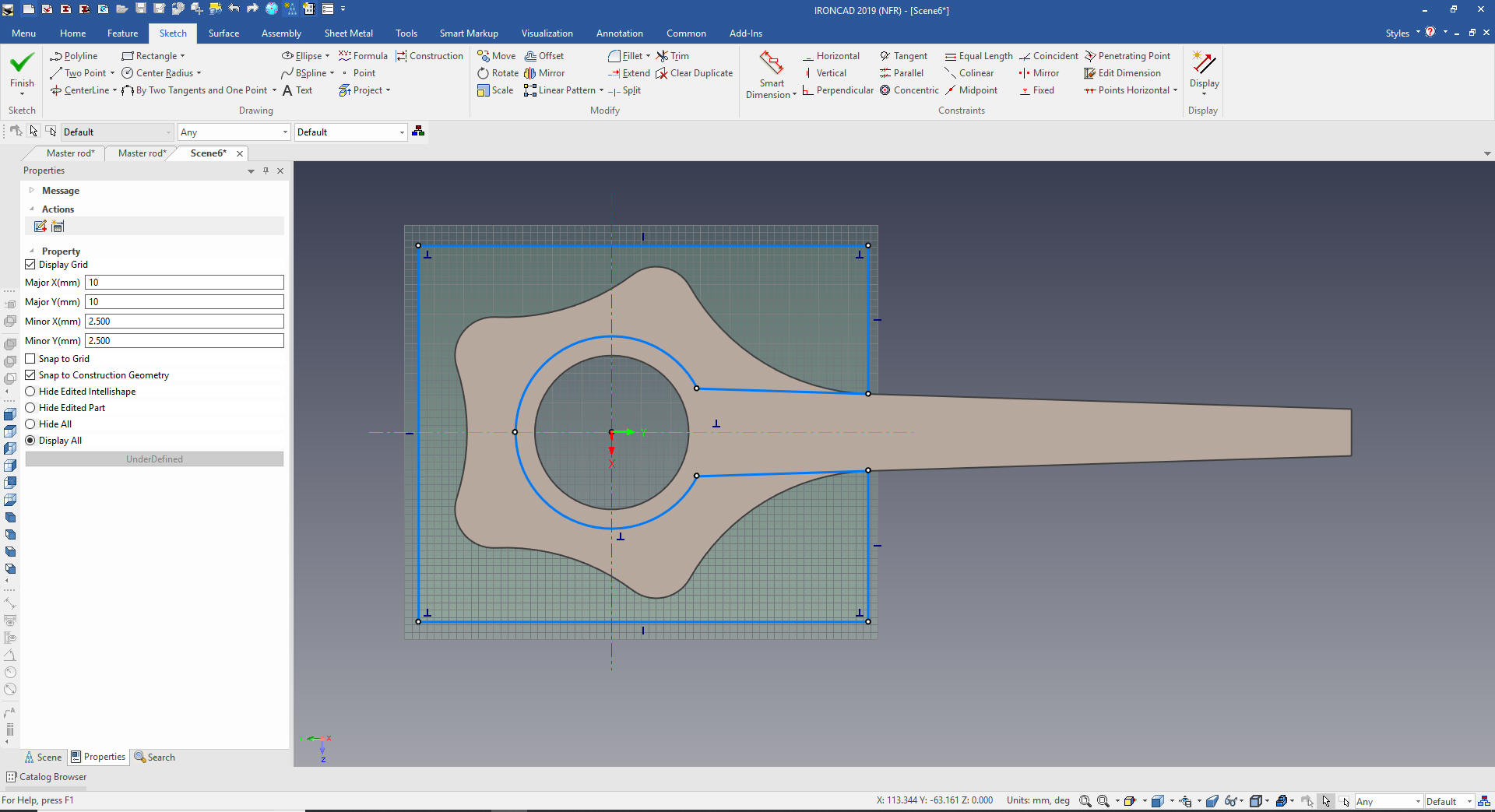
Now
for the center cut we create a standalone sketch on the YZ plane.
Project the lines and offset the circle and create a rectangle to
create the cut out sketch.
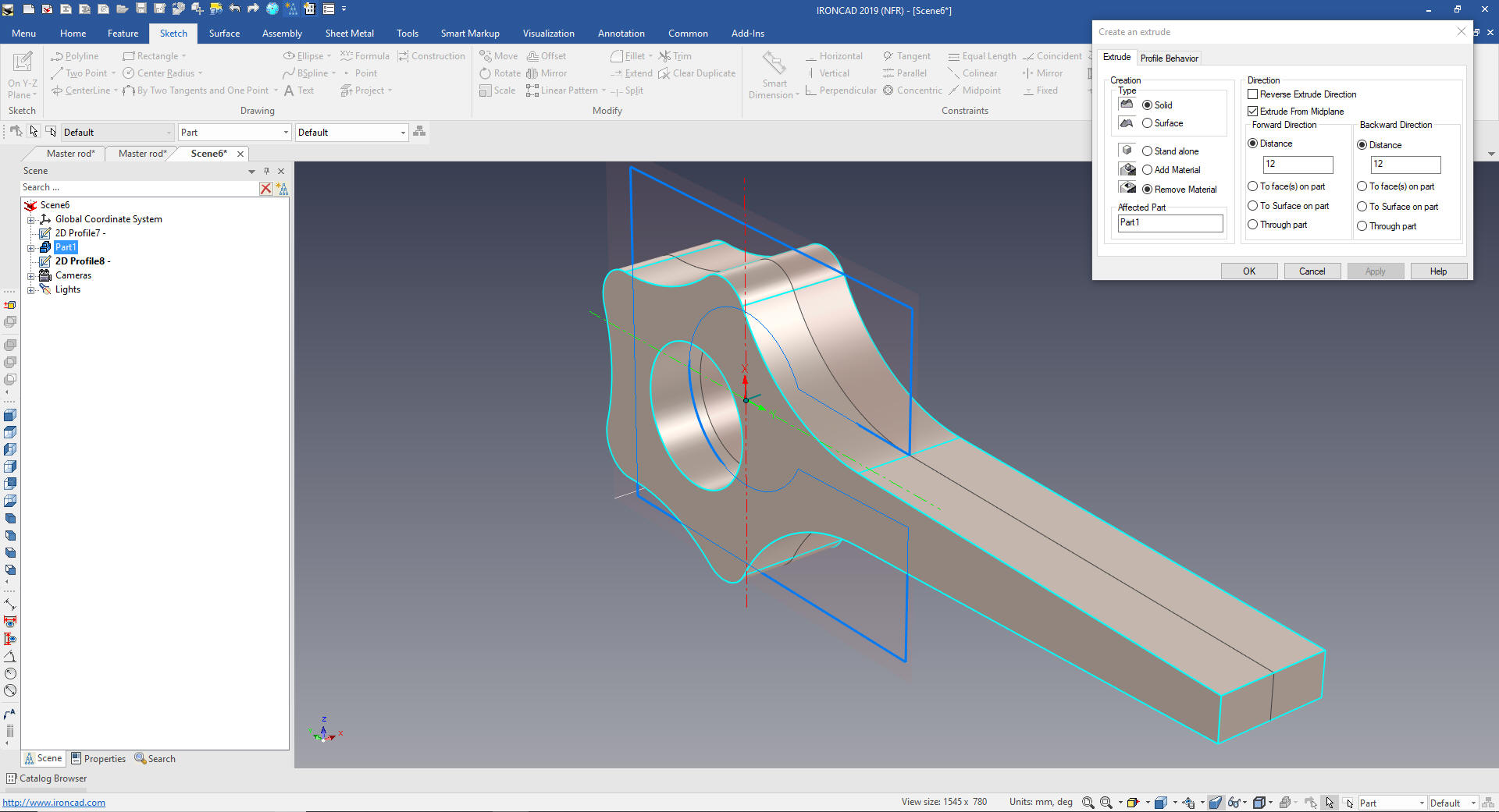
We will extrude and set to remove from the existing solid.
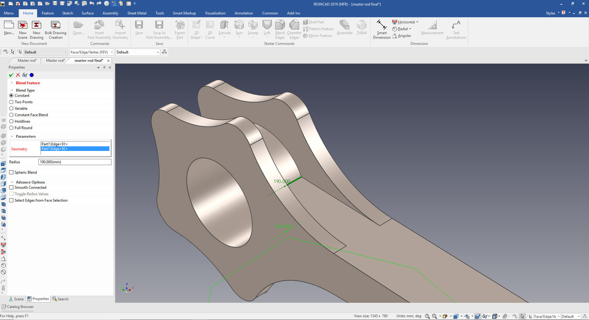
We
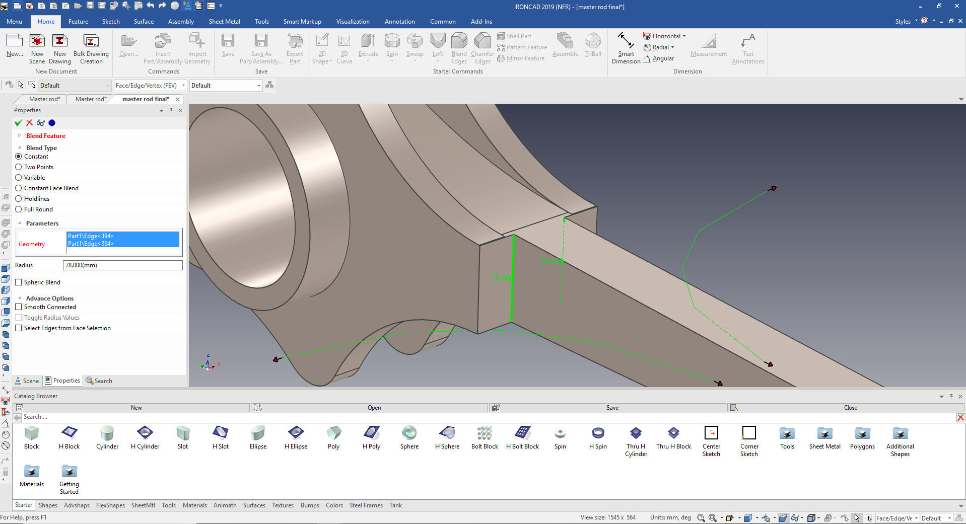
now need to add the 190m blends.
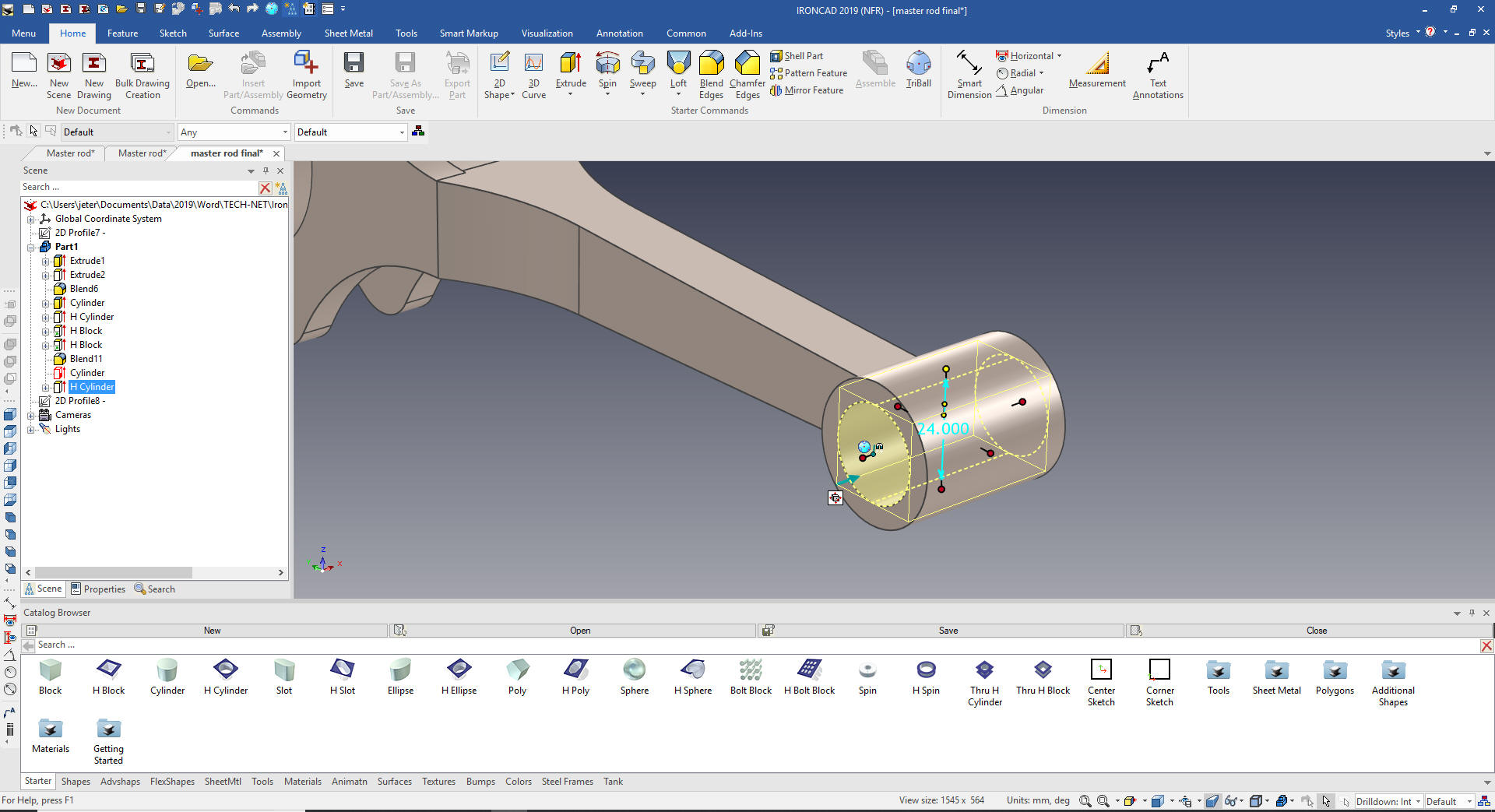
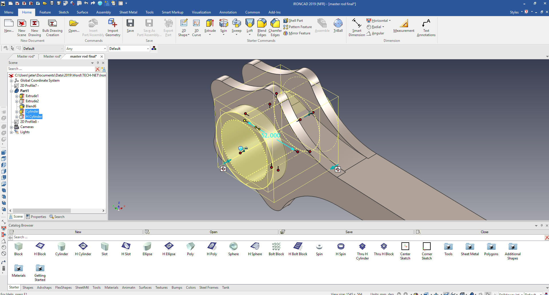
We
now add the center boss and hole by dragging and dropping a
cylinder then a hole cylinder from the catalog and size them. You
can see I have enabled the catalog so you can see it. Usually it is
hidden for more scene landscape.
What are these shapes? We call them
intellishapes. All are based on sketches that can be edited.
IronCAD was first released as Trispectives a graphic design package
and they called the workspace the scene.
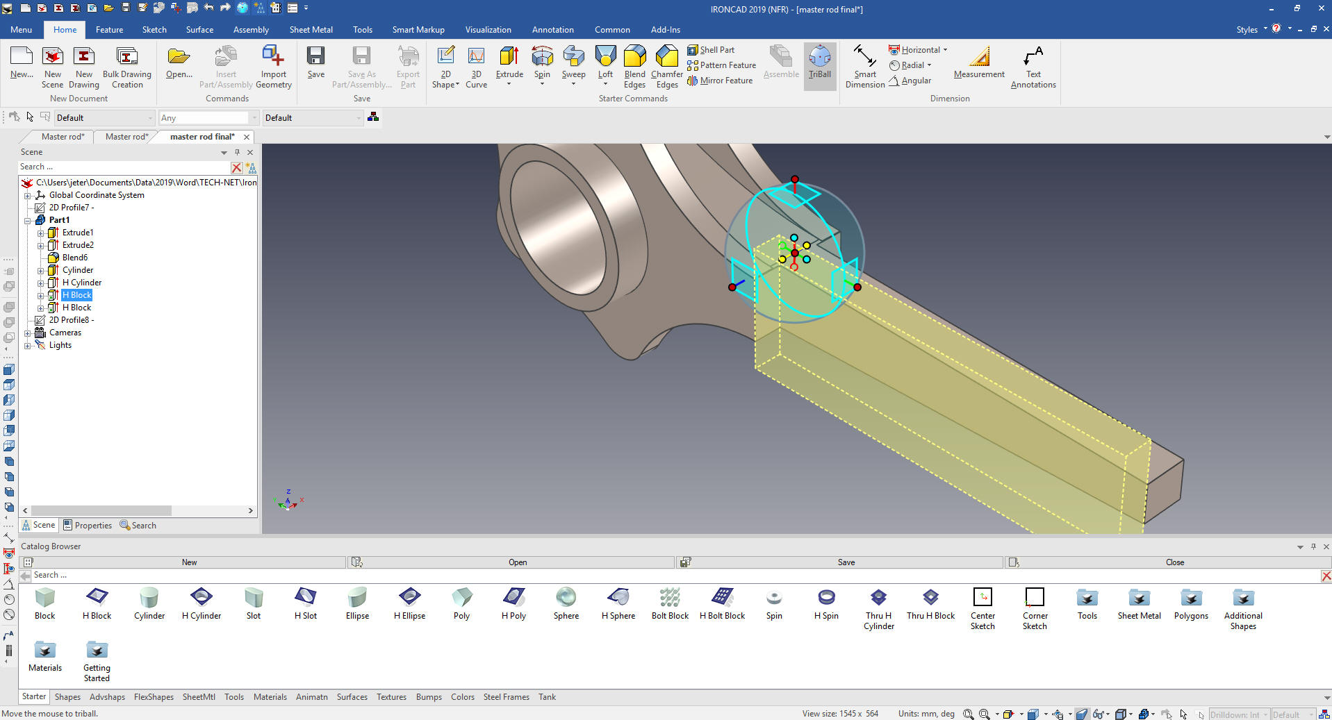
We
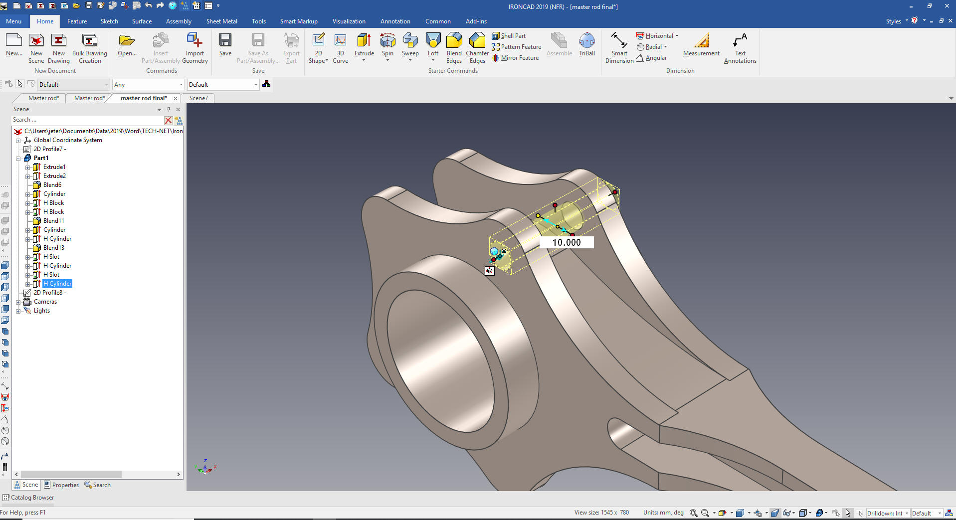
now add the side cuts by dragging a hole block locating and size it. We
mirror using the Triball and link it.
W
We
add the fillet in the cut and on the end boss and were are ready our
end boss and hole.
We
drag and drop and cylinder on end and size it. Then drag and hole
cylinder to the center of the boss and size it.
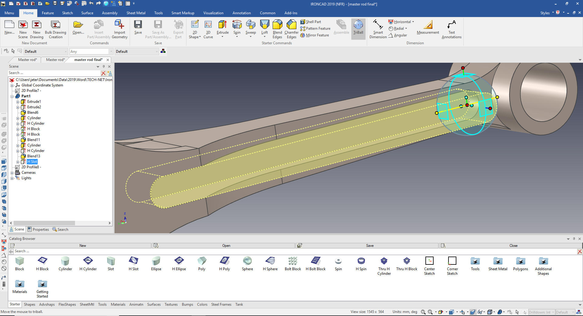
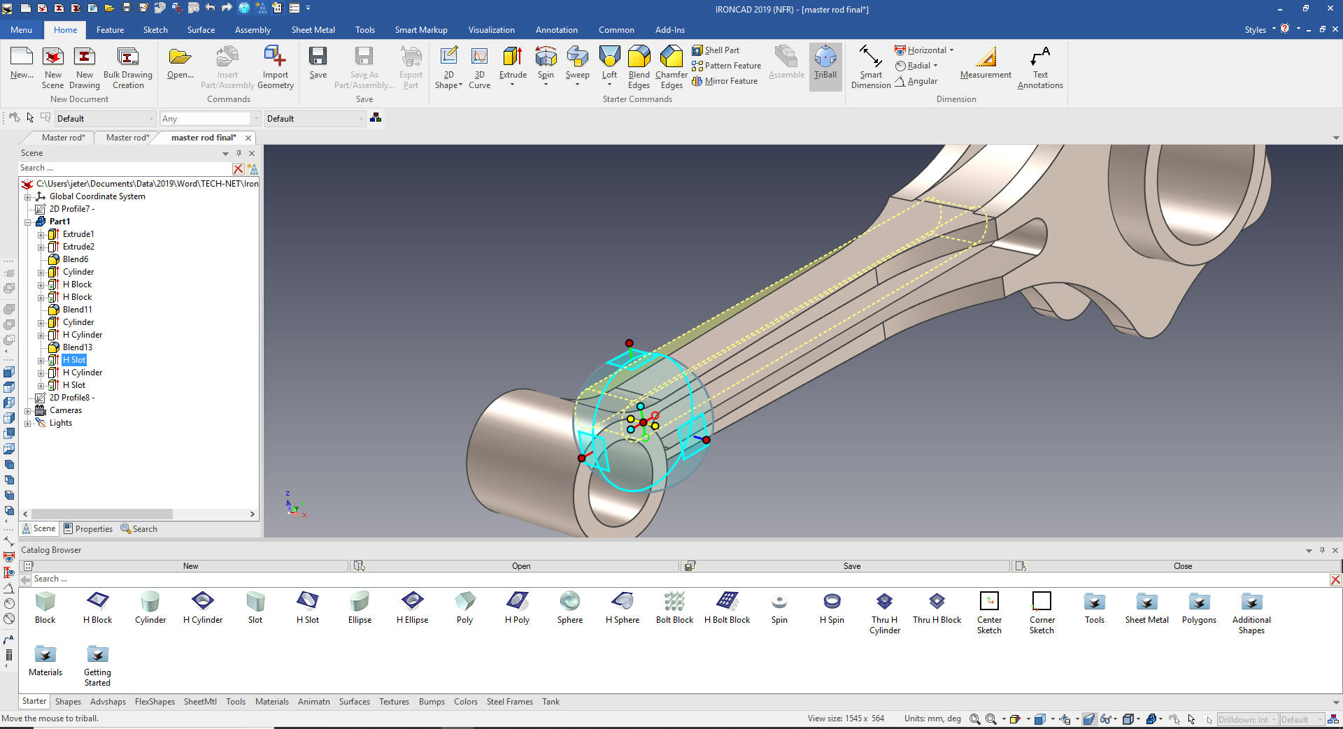
We
add the blend and drag and drop a slot on a center point and size
it.
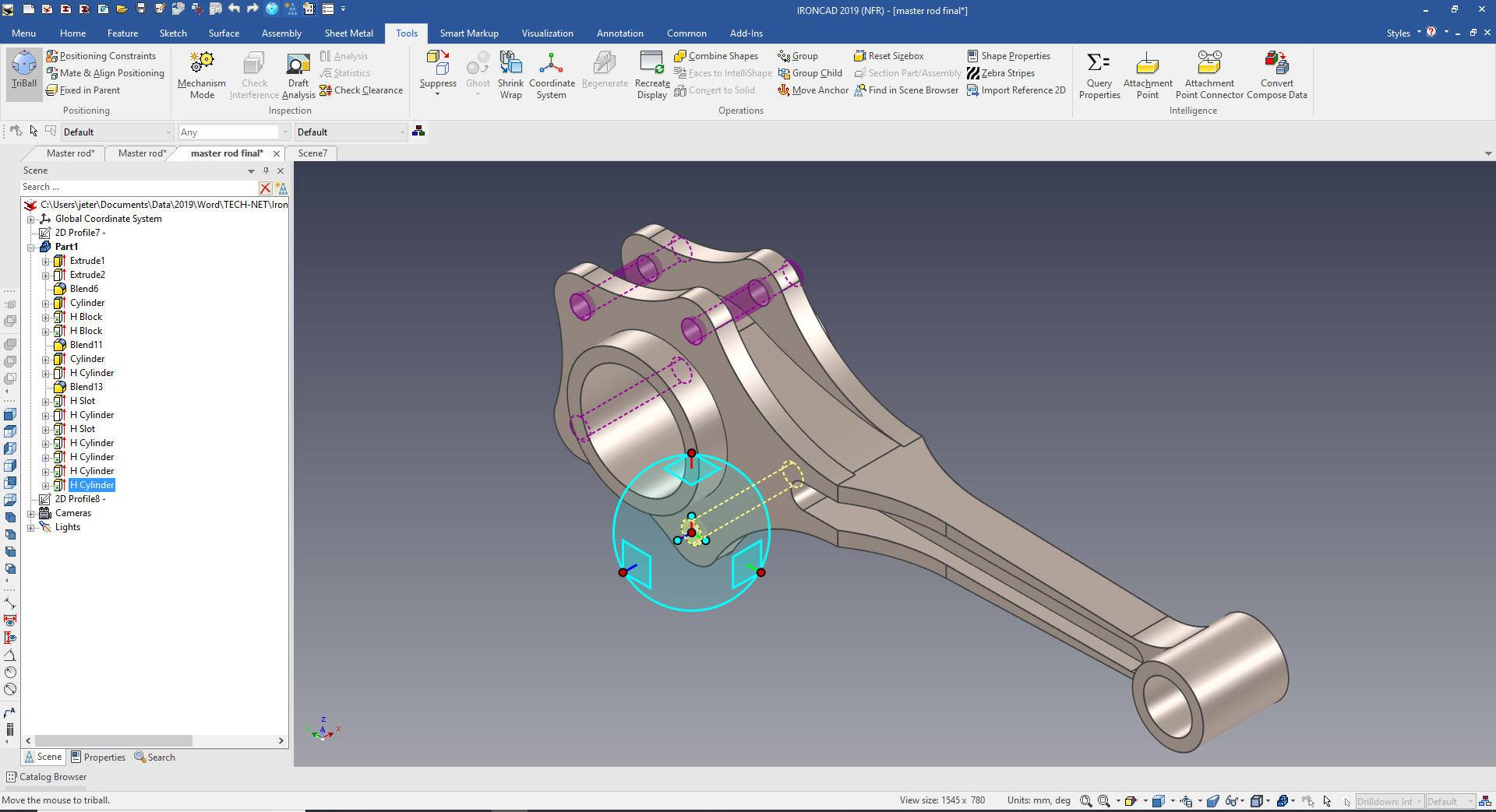
We mirror link the slot with the Triball.
We
add the 10m holes by dragging and dropping a hole cylinder on the
center of one of the tabs.
We
use the Triball to link the hole to the center of the other tabs and
we are done.
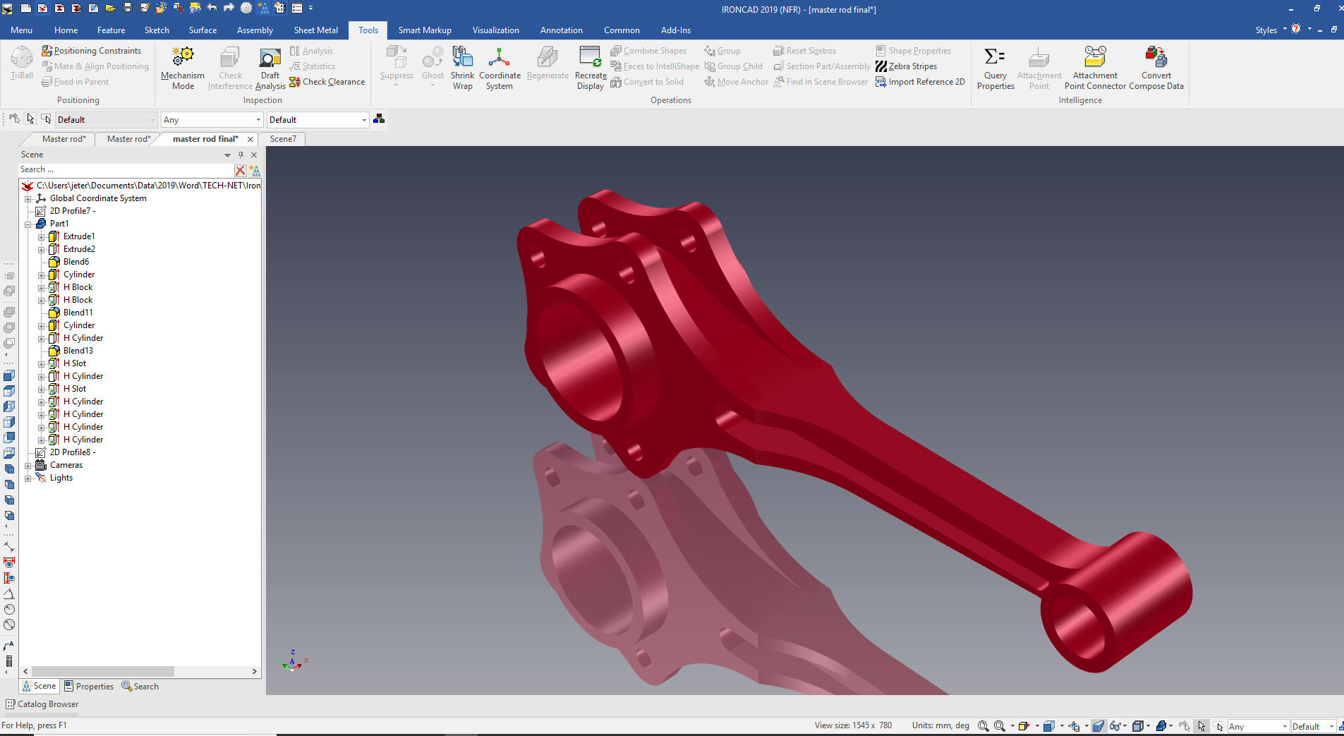
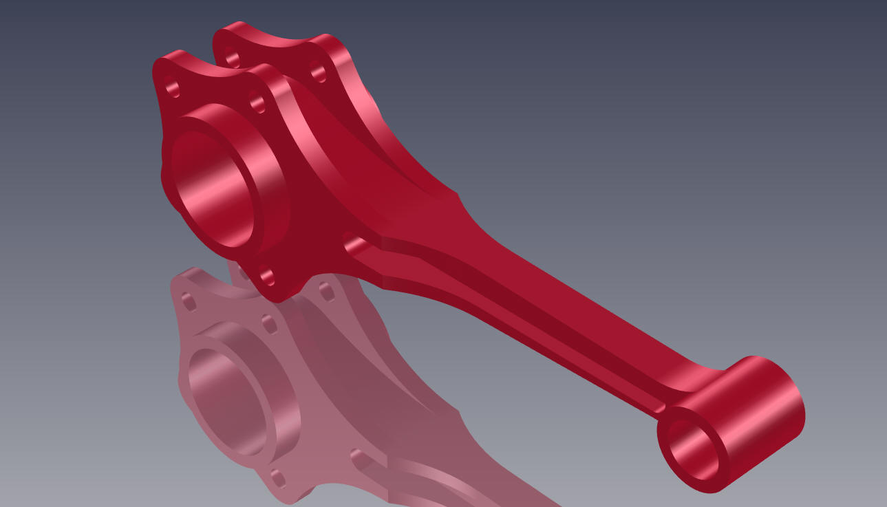
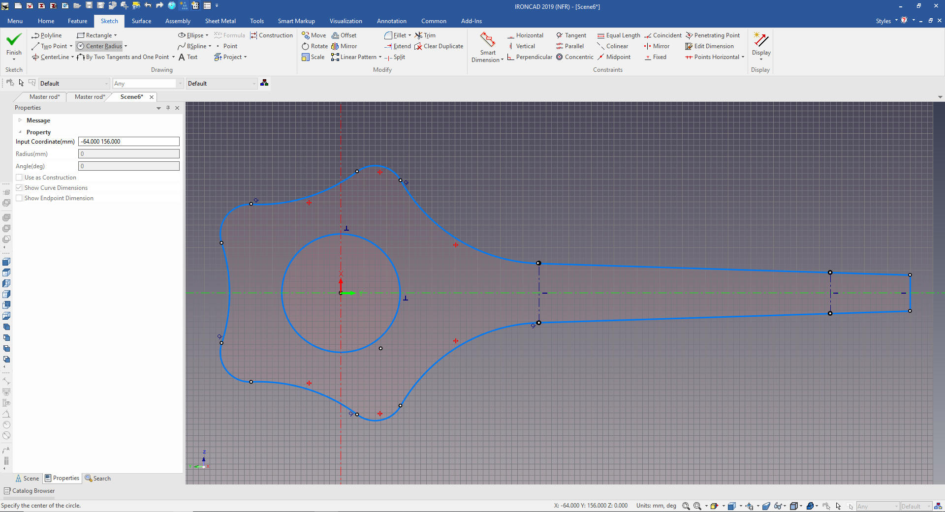
Here
is the final part. We did two sketches, the poor Catia presenter
made this part so much more complicated.
I can't imagine hundreds of Boeing, Airbus, Gulfstream and
Bombardier designers struggling with CATIA and constrained sketching
only.
Since
we didn't have a drawing we will now create the AID. IronCAD has a
separate documentation module. Since IronCAD is a Single Model
Design Environment we can have complete projects in two files.
But if you have the job of converting drawings to 3D you have to
create a drawing to check to see it the model is correct.
It is
very important that you look into how you or your engineers are
creating the parts. Streamline Sketching and Feature Based Modeling
is easy to learn and implement. It, alone, will increase
productivity 10X. Now, IronCAD with its unique integrated
history/direct edit functionality can increase your productivity
another 5X or more with changes! Again, time is money in
engineering.
More on Streamline Sketching and Feature
Based Modeling.
To experience this increased level of productivity, please download
IronCAD for a 30 day evaluation. Legacy data is no problem, IronCAD
can read the native files of all of the popular programs. IronCAD is
a great replacement for the subscription only Autodesk and PTC
products.
Give me a call if you have any
questions. I can set up a skype or gotomeeting to show this part
or answer any of your questions on the operation of IronCAD. It
truly is the very best conceptual 3D CAD system.
 W
W