IRONCAD vs Fusion 360 Lesson 6 3D Modeling Techniques Defined Streamlined Sketching/Feature Based Modeling
When I introduce IronCAD's very
flexible design paradigm I have a hard time to get the Pro/e clone
users, like Solidworks and other programs to understand the drag and
drop design paradigm.
Download
IronCAD/Inovate and take
the one day and 17 lesson course. I get rave reviews from my new
customers. Give it a try, this is a fully functional 30 day
evaluation with all of the native translators so you have access to
your legacy engineering information.
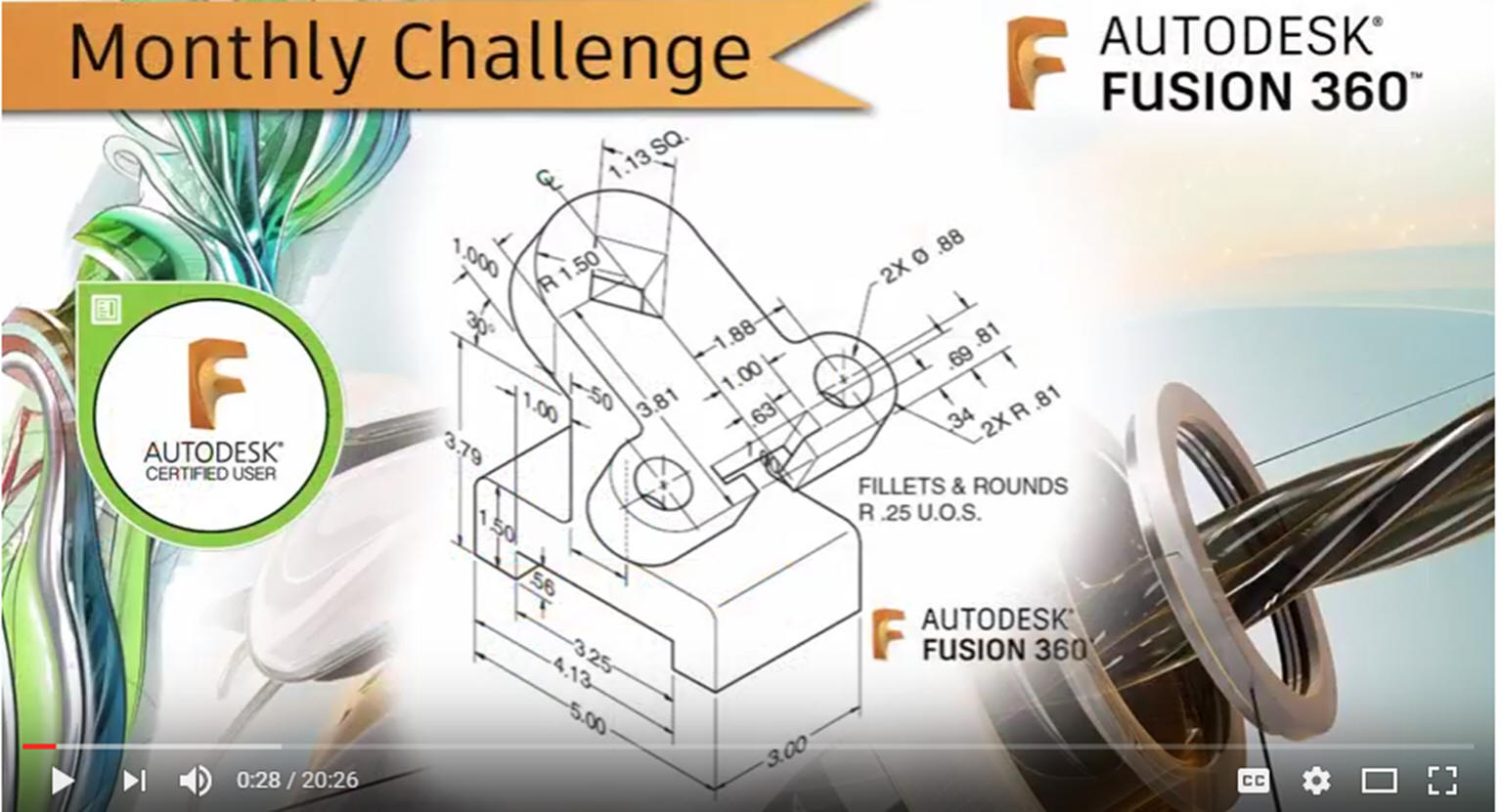
IronCAD Self-Pace Training Course I saw the
following video challenge on linkedin and thought I would give it a
try on IronCAD. I actually did it before I watched the video, so I
did it a bit differently. This will give you an idea how different
and flexible IronCAD is compared to the conventional Pro/e clone and
to the not so conventional Fusion 360.
I would do a
video, but I really am not good at it. So I will show you step by
step. I will try and get IronCAD support to create one. They are
very good.
I always create the part before I watch
the Fusion 360 Video, so as to not taint my process. Of course,
there are a multitude of ways to create a model. There is no right
way, just more productive ways. From what I have seen from these
very complicated processes done by the Fusion 360 fellow, it is not
just limited by the 3D CAD system.
The modeling technique is
hugely responsible for the level of productivity. Those of you that
are only trained in the sketch, sketch, constrain, constrain world
are truly limited by not using the freedom of feature based design,
that is available in even the most Pro/e-ish of CAD systems. If your
designers are designing in these very unproductive and time
consuming processes it might be time to review your standard design
processes. Don't have any do you?
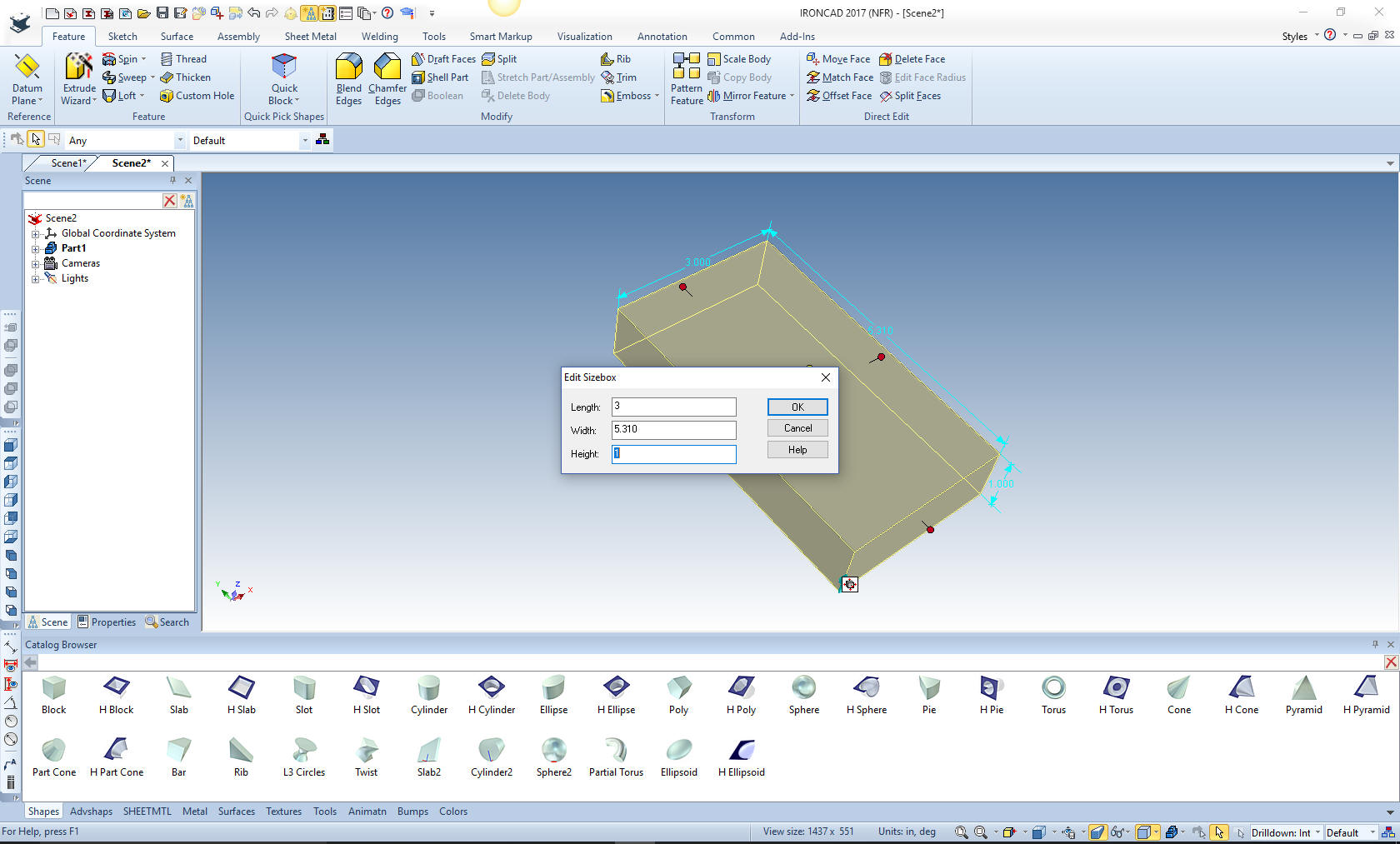
Here is IronCAD. My default is inches so lets get started. I will
drag a block from the standard shapes catalog and size it.
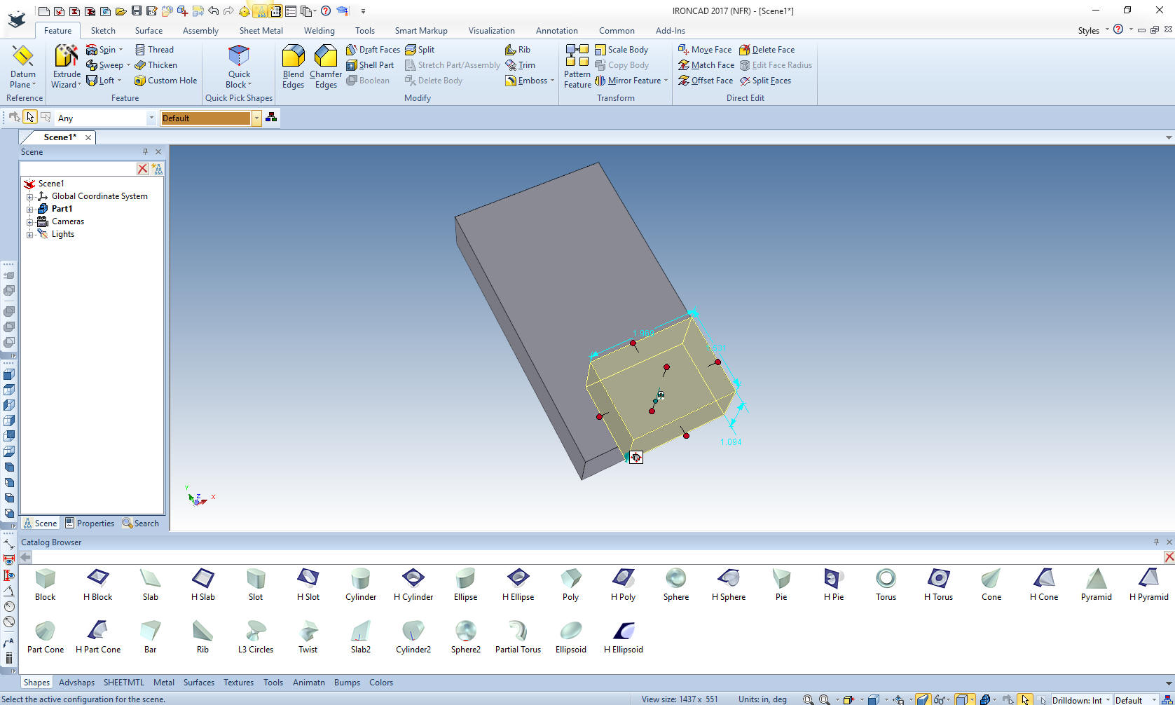
We drag another
block on to the first block from the standard shape catalog. You can
create custom catalogs with common features, parts and assemblies.
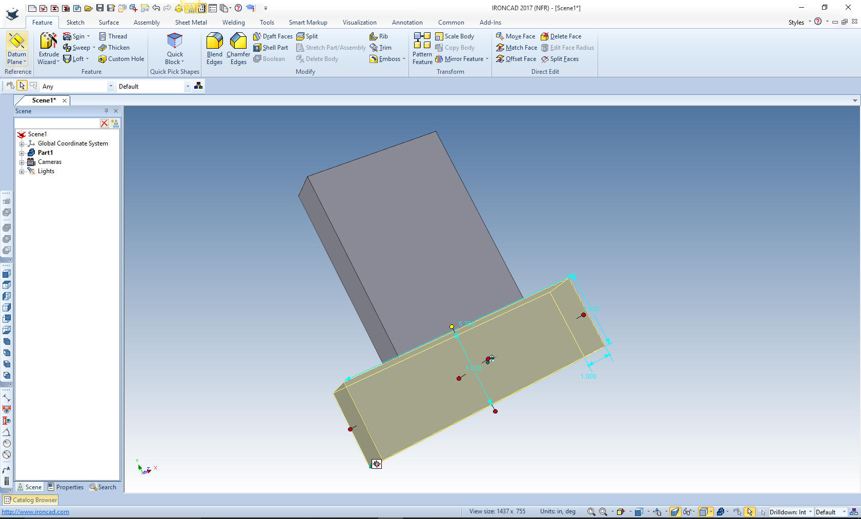
We size the lower
block, by pushing and pulling to points and faces, modifying a
dimension or two. In this case I aligned the block to the middle and
bottom of the existing block and added the two dimensions (1.88+.81)
in the input then doubled it and set the height to 1.62.
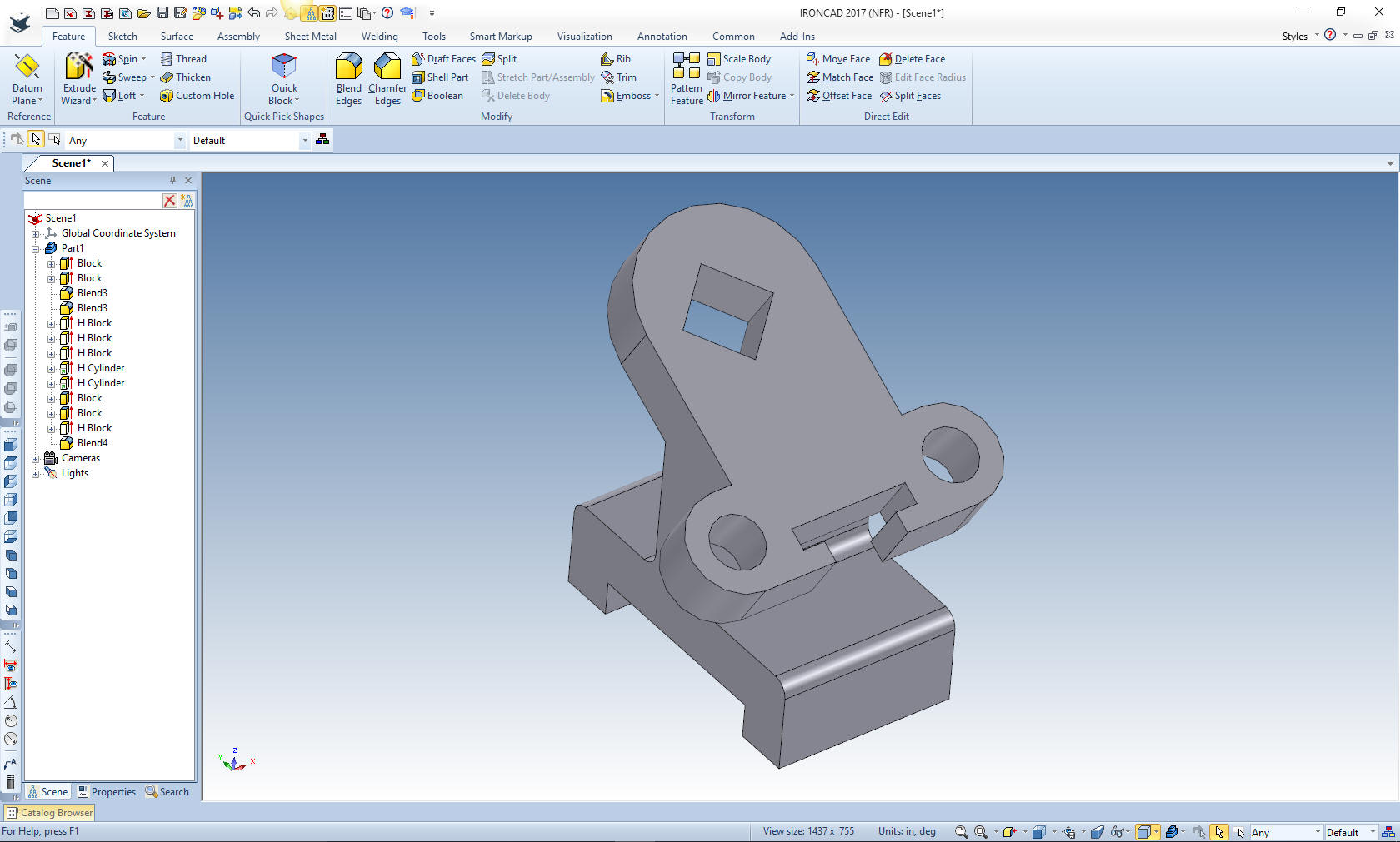
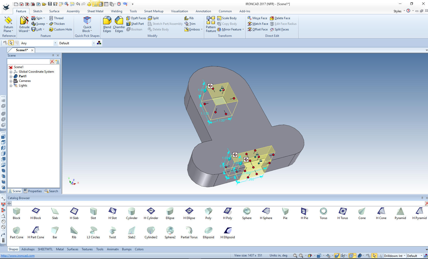
We add the 1.50 and .81 blends and create the cutouts with hole
blocks and size them
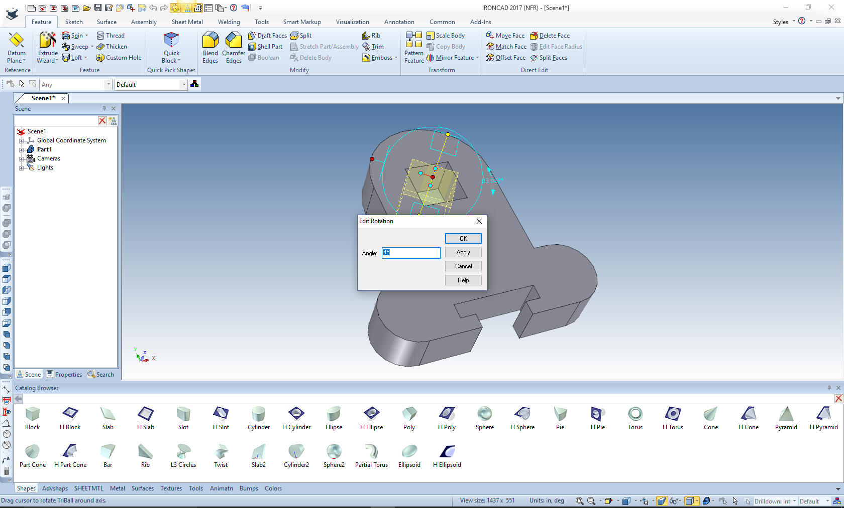
We now
select the top hole block, turn on the triball and rotate 45
degrees.
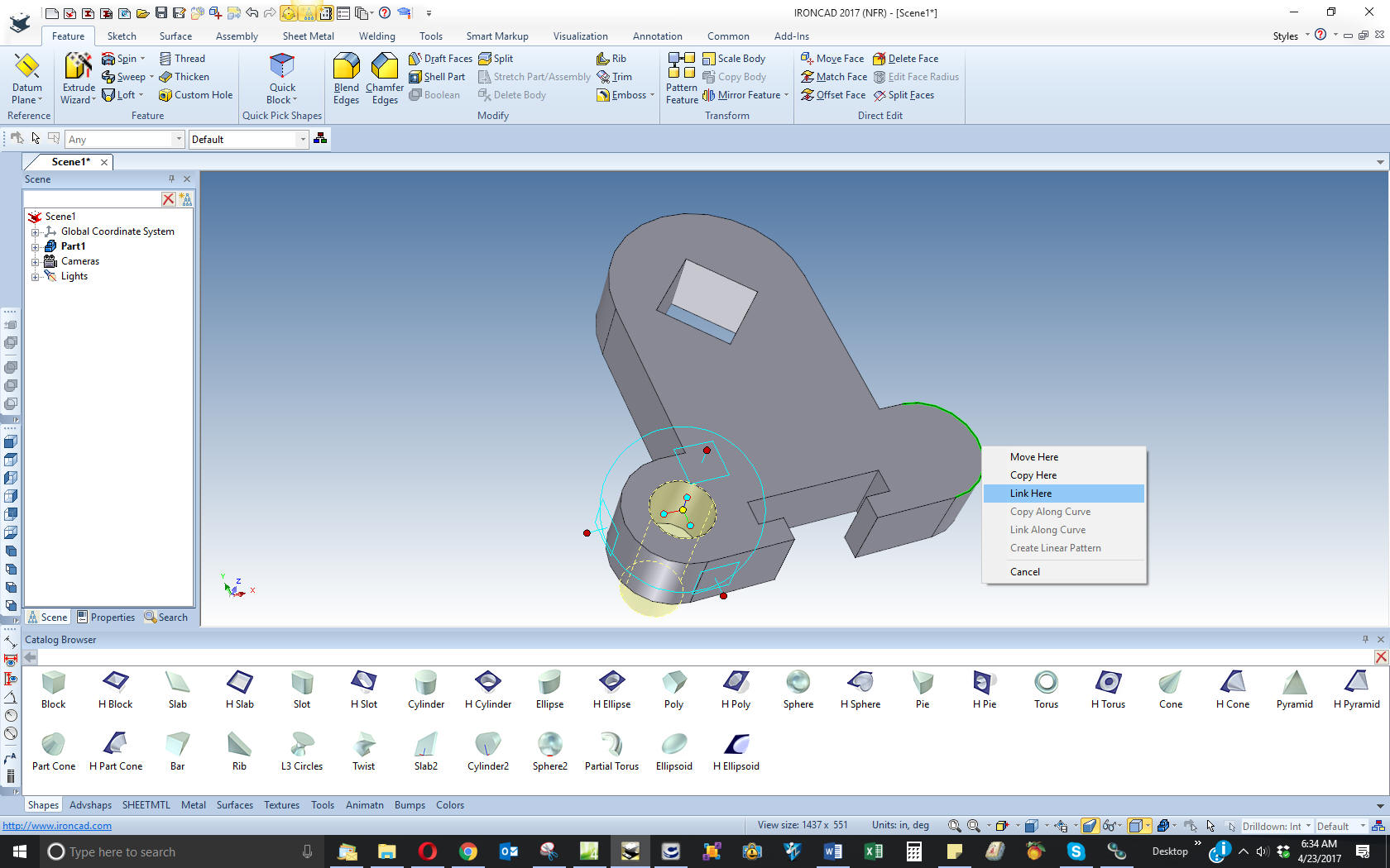
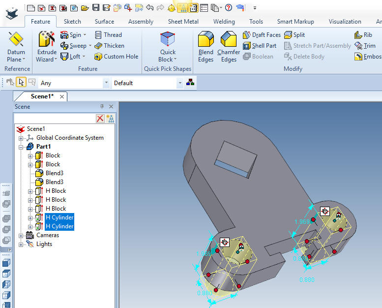
I drag a hole
cylinder to the center of the lower tab. I then use the triball to
"link" it to the center of the other tab. That way I have an
associative relationship with the two holes. When just duplicating a
drawing this may not be important, but it can become incredibly
important when doing conceptual design. Again, remember, duplicating
parts from drawings does not show the full design flexibility of the
CAD system.
Notice in the
scene browsers these two hole are linked. You can see the small
arrows denoting this. We can link features, parts and assemblies,
including mirroring.
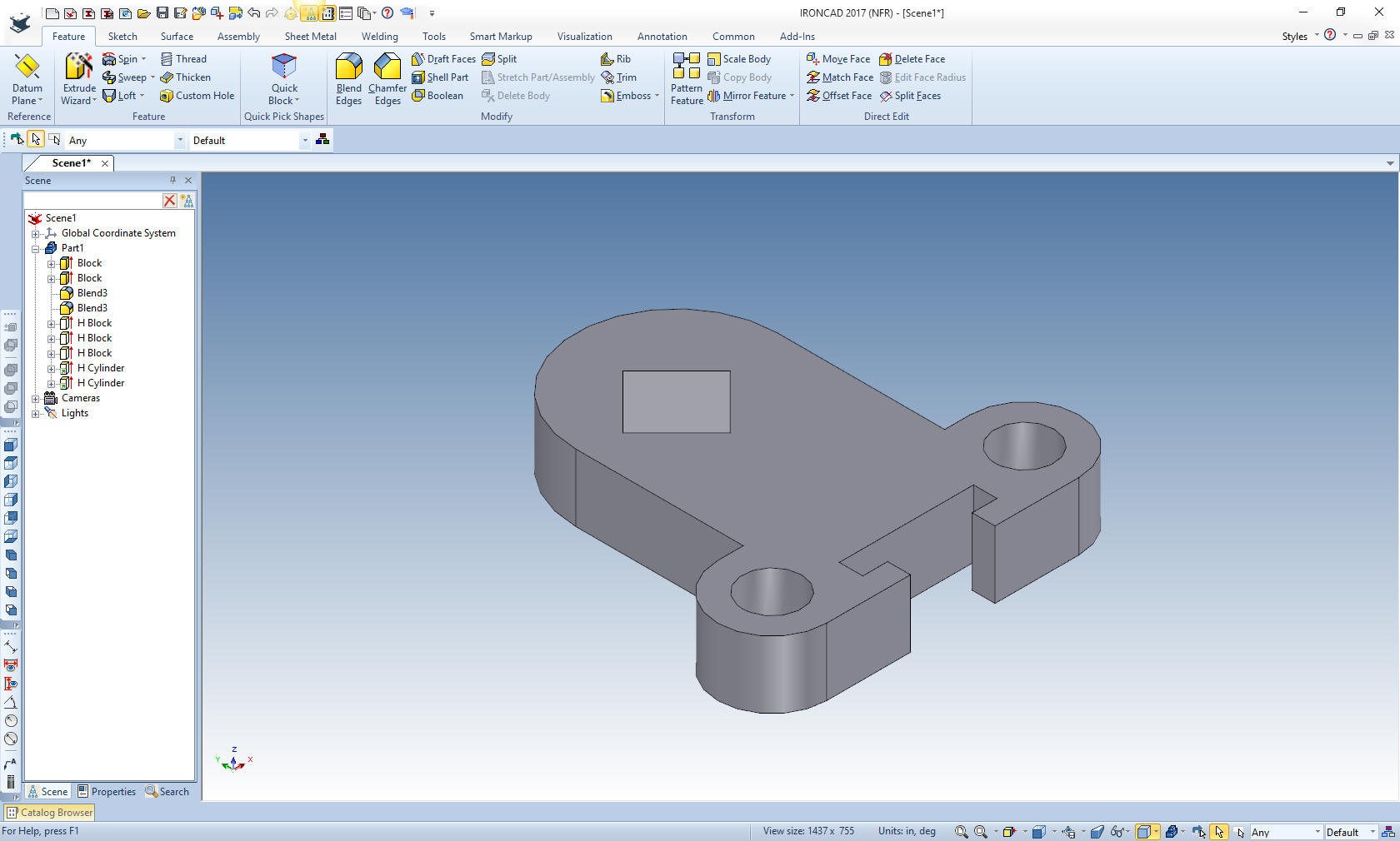
We are done with
the top portion of the part. The Fusion 360 fellow probably thinks
he is clever by half by sketching half of the part. He could have
easily sketched the complete part faster. When you are teaching
techniques you only use the ones that have to be used to increase
productivity in that situation not to create extra steps.
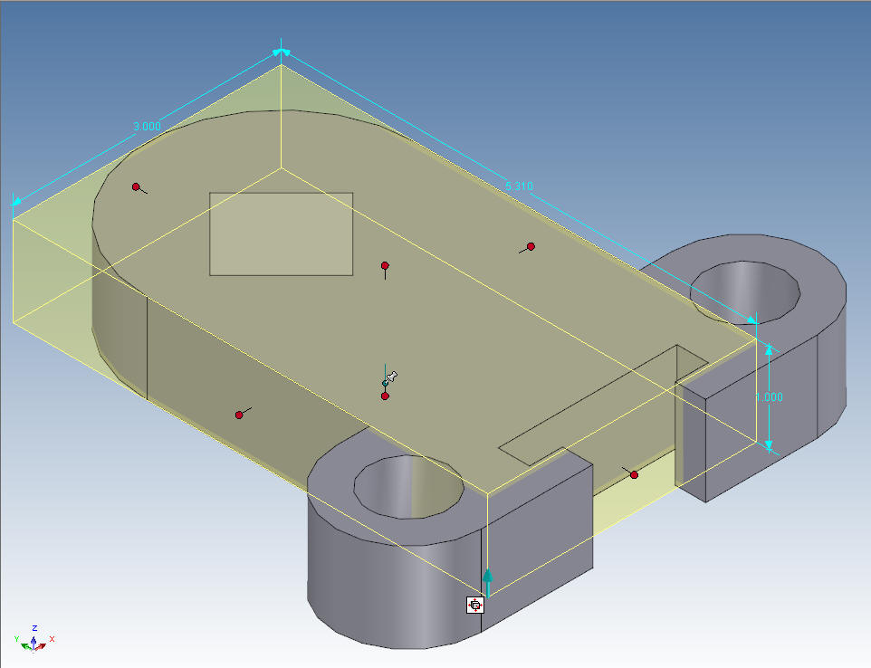
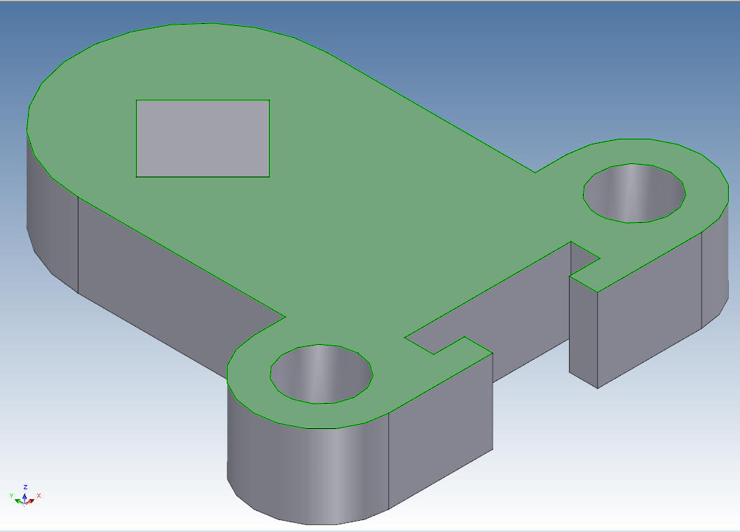
Ironcad has levels of the process. The top level is the assembly and
it is yellow, the part level is blue, the feature is again yellow
with all of the construction information shown and then the face,
which is green. You can edit your design at any of these levels. You
get to the different levels by clicking on the assembly, part,
feature or face.
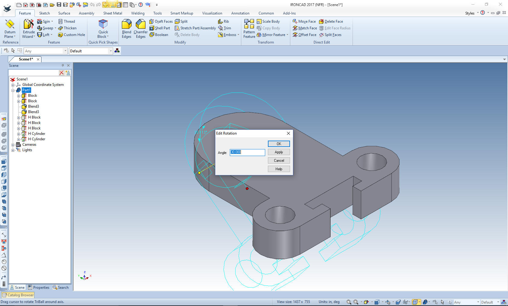
I created this portion in the global coordinate system just for
ease of construction. So I have to rotate it the 30 degrees to get
it oriented correctly. I will explain why later.
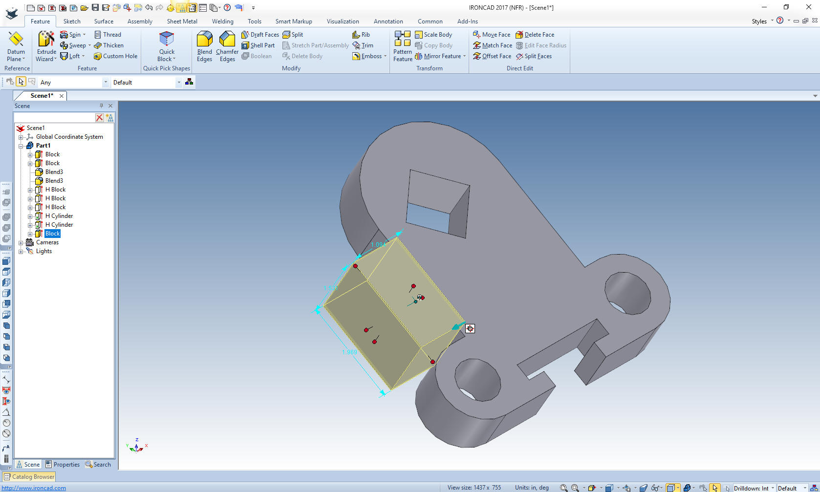
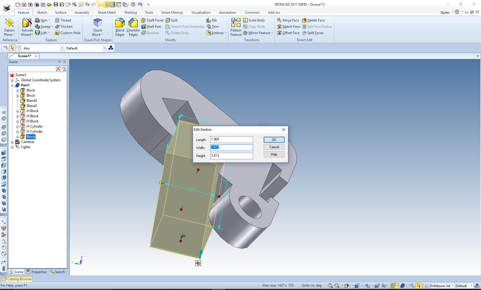
I am now dropping
a block on the side face, notice it comes in related or in the
orientation of this portion of the part.
We
need to get the block back in the global coordinate system to
continue with the part. Yes, I could have sketched it, or even
dropped a block in space and Boolean joined them later. But you must
see the cleverness of the powerful triball. The triball is one of
the most incredible tools in all of 3D CAD. Many 3D CAD systems have
manipulators but they are very limited. In this application I just
select "Orient triball to global" and the part is oriented
correctly.
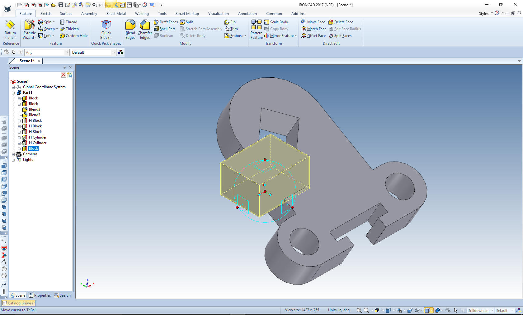
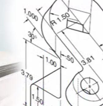
Yes,
there is a rhyme and reason for this step. Notice in the original
drawing there is a .50 dimension. It seems like the Fusion 360
fellow ignored this dimension.
With push and pull design
you can use the features as construction and size them accordingly.
We will align this block with the center of the square hole on the
top face of the upper portion then subtract the .50 to establish the
location of the face. Even though these steps are fast and easy they
have to be shown.
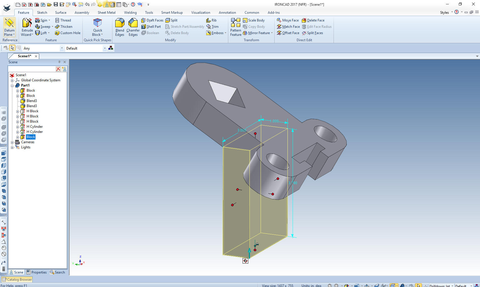
We now
pull the top of the block to the intersection of the block and lower
face of the upper portion and proceed to size the block. Now there
is no thickness for this block on the drawing but it looks
approximately 1 inch.
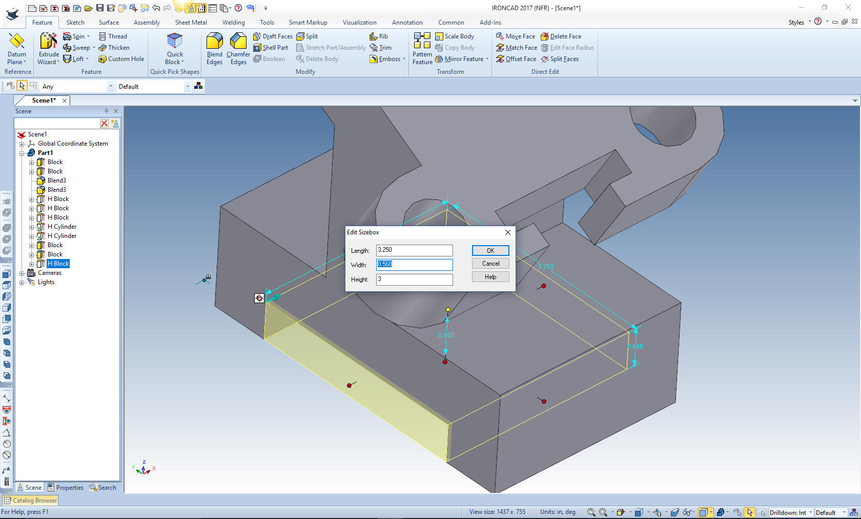
We
drag another block on the the last block and size it enough to
create the bottom hole block. Since the bottom hole block seems to
be a driving factor we had to jump through a couple extra pulls and
pushes to size the bottom block.
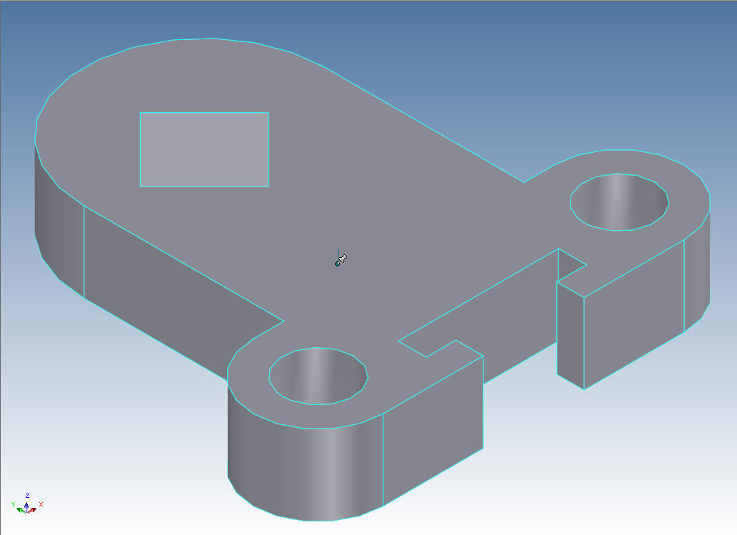
We add the blends and we are done. I had to show a couple of extra
images to clarify the complete process since most were incorporated
in the same step.
It is more than just technique that makes
this part so easy it is IronCAD's incredible drag and drop design
functionality. Not one sketch or constraint was used in this model.
Please realize how incredible and more productive that is. You can
easily realize productivity increases of 5X on conceptual design and
10X on changes. But it is not just modeling that allows this level
of increased productivity
Take a look at this video showing this
design process compared to Solidworks and any other Pro/e Clone
world of sketch, sketch, constrain, constrain.
It is
very important that you look into how you or your engineers are
creating the parts. Streamline Sketching and Feature Based Modeling
is easy to learn and implement. It, alone, will increase
productivity 10X. Now, IronCAD with its unique integrated
history/direct edit functionality can increase your productivity
another 5X or more with changes! Again, time is money in
engineering.
More on Streamline Sketching and Feature
Based Modeling.
I have created some Learning IronCAD
Lessons. They are more than just showing you how
to use IronCAD they go into the design philosophy of this highly
productive product as compared the the conventional Solidworks
clones.
To experience this increased level of productivity, please download
IronCAD for a 30 day evaluation. Legacy data is no problem, IronCAD
can read the native files of all of the popular programs. IronCAD is
a great replacement for the subscription only Autodesk and PTC
products.
Give me a call if you have any
questions. I can set up a skype or gotomeeting to show this part
or answer any of your questions on the operation of IronCAD. It
truly is the very best conceptual 3D CAD system.