3D Modeling Techniques IRONCAD vs Solidworks Lesson
Eleven Streamlined Sketching/Feature
Based Modeling Two Similar Parts and AIDs:
Two Files Bonus: Direct Edit Defined!
When I introduce IronCAD's very
flexible design paradigm I have a hard time to get the Pro/e clone
users, like Solidworks and other programs, to understand the drag and
drop design paradigm.
Download IronCAD/Inovate and
take the one day and 17 lesson course. I get rave reviews from my
new customers. Give it a try, this is a fully functional 30 day
evaluation with all of the native translators so you have access to
your legacy engineering information.
I saw some Fusion 360 exercises online and I decided to compare
IronCAD. It quickly turned into a study in modeling techniques. I have created
many comparisons to Fusion 360, Onshape, Solid Edge, NX, Creo,
Catia and Inventor
lessons to show the difference between
IronCAD and my modeling techniques. I found the presenters working
identically wasting massive amounts of time
with overly complex constrained sketching procedures. I was so unimpressed that
I decided to model the parts or assemblies showing my modeling techniques plus IronCAD's superb design system.
3D Modeling Techniques Defined
Many of these modeling techniques can easily be implemented even
within their existing system. I call it Streamlined Sketching and
Feature Based Modeling. Please review a few of the above IronCAD
comparison lessons, there are some very stark differences.
While creating 3D models from drawing is the very best
way to learn 3D CAD and maybe some design techniques it does not
expose the designer to the design flexibility necessary in design. IronCAD is all top down due to the single model environment.
Creating mating parts is a cruise. But modeling is just one aspect of a
well designed productive 3D CAD system.
Solidworks
is a marginal 3D CAD system based on the dated Pro/e (Creo) history
based modeling system. I have sold this product years ago and found
it, like all of the other Solidworks clones, not productive enough
for our engineering department. We use what we sell. That gives us
the experience to effectively support our user base.
I would do a
video, but I really am not good at it. So I will show you step by
step. I will try and get IronCAD support to create one. They are
very good.
As with my Ironcad vs Fusion 360 exercises
I have found the same problems with Solidworks. The modeling
technique is hugely responsible for the level of productivity. Those
of you that are only trained in the complex and time consuming
constrained sketching world are truly limited by not using the freedom of
Streamlined Sketching and Feature Based Modeling, that is available in even the most
Solidworks-ish of CAD systems. If your
designers are designing in these very unproductive and time
consuming processes it might be time to review your standard design
processes. Don't have any do you?
Let's get started!
You will see
with Streamlined Sketching and Feature Based modeling is much more
productive and flexible. It gives you a more real world feel to
your design process and is a much more pleasurable and productive experience.
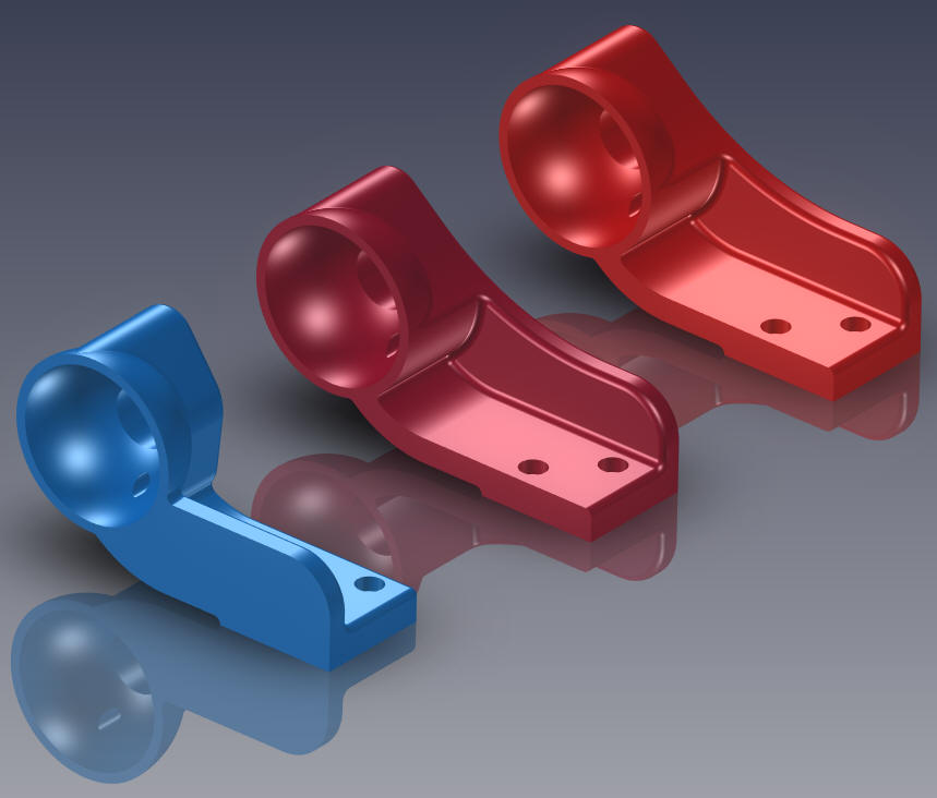
We will start with -1 Mount
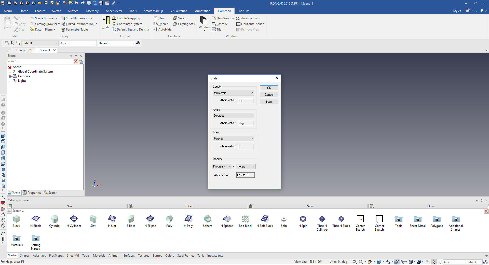
We set the units to mm
Most of the time you start in IronCAD by dragging and dropping from
the catalog but we will start with a sketch on this part.
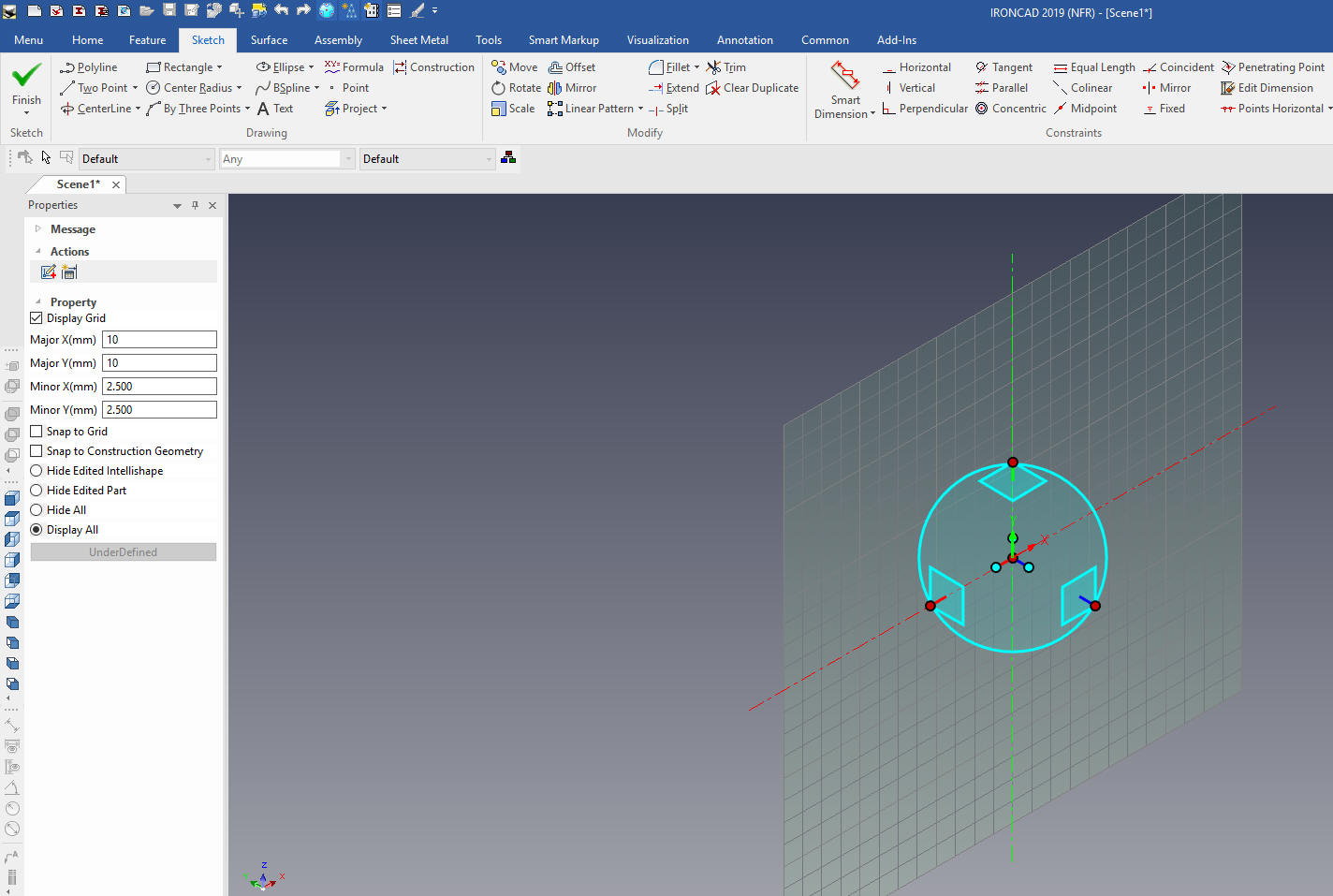
IronCAD's sketching planes are an integrated
part of the feature. So we do not have starting planes. It does have
a basic coordinate system with planes but they get more in the way
then help.
Using the Extrude Wizard we insert a sketch
plane into the scene. It is automatically put at X0Y0Z0. We use the
Triball to move it to the correct orientation.
Note: Why does IronCAD
call it a scene instead of a workspace? IronCAD was first released
as a graphic design program called Trispectives. It still has much
of the graphic design functionality. It truly is a wonderful mixture
of professional 3D CAD and graphic design, which puts it in a much
more flexible category as compared to the very mechanical
engineering focused Solidworks clones.
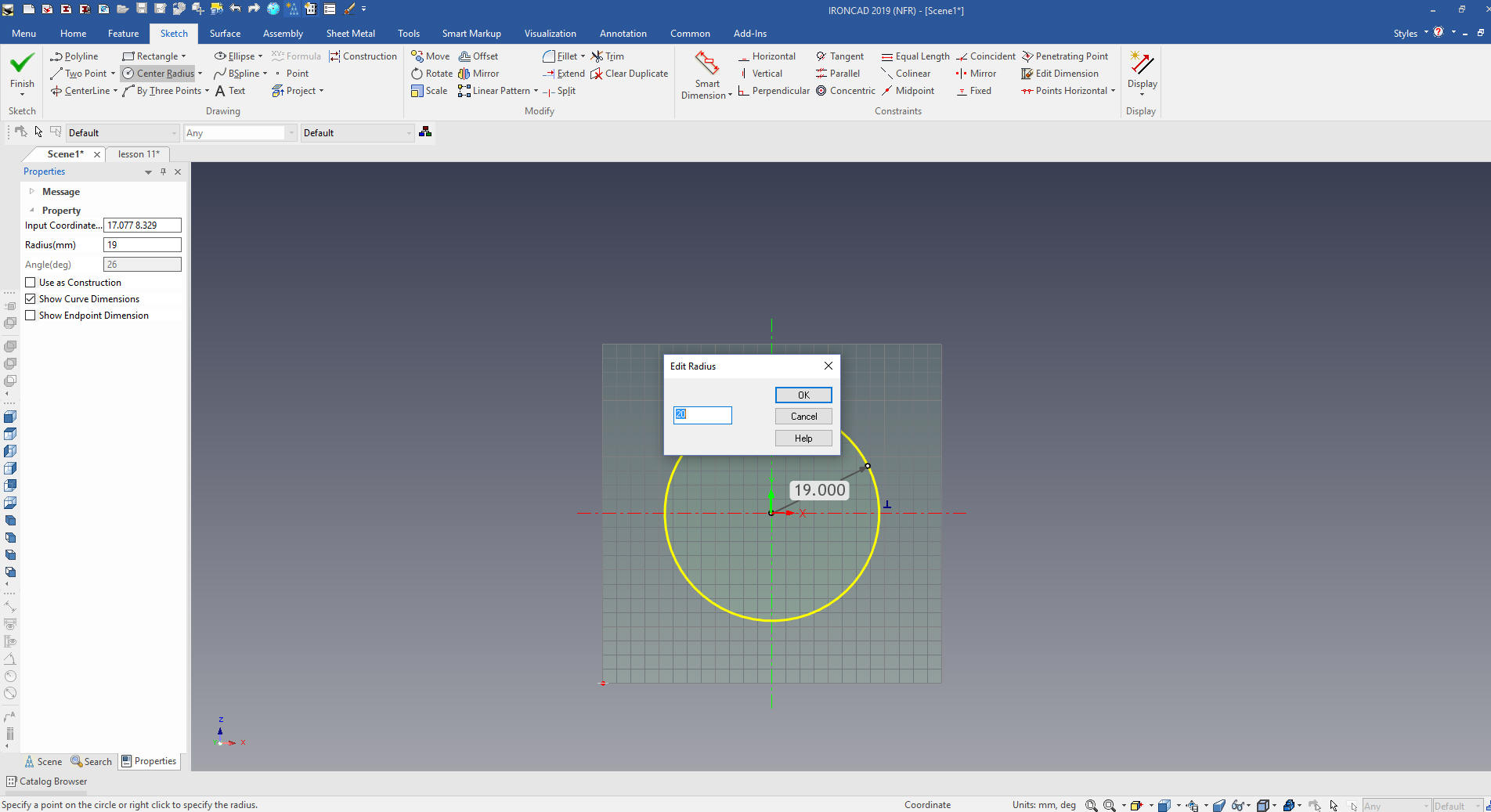
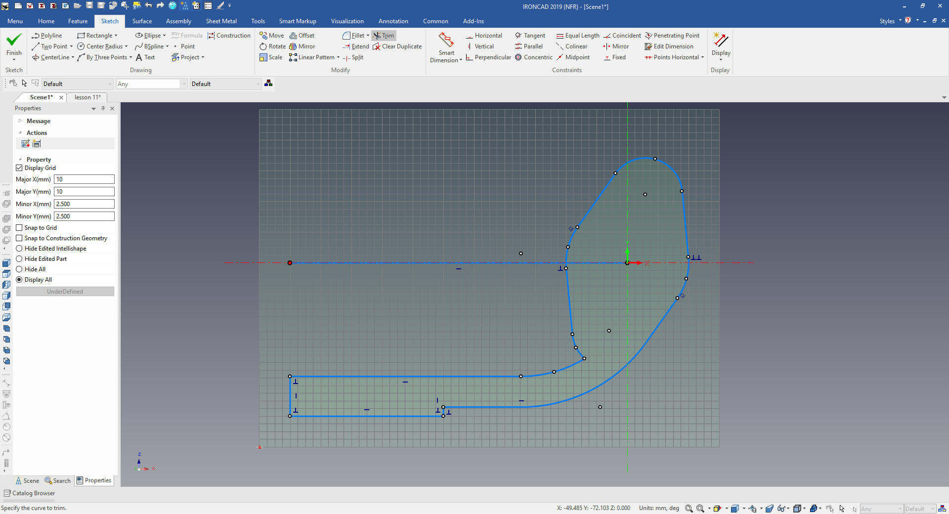
We look directly
at the sketch and start defining our profile. We select circle with
radius and using the right mouse button to define the circle and a
dialog box will come up an let you size the circle.
The left button is explicit and the
right button give you the option to set the size of most entities.
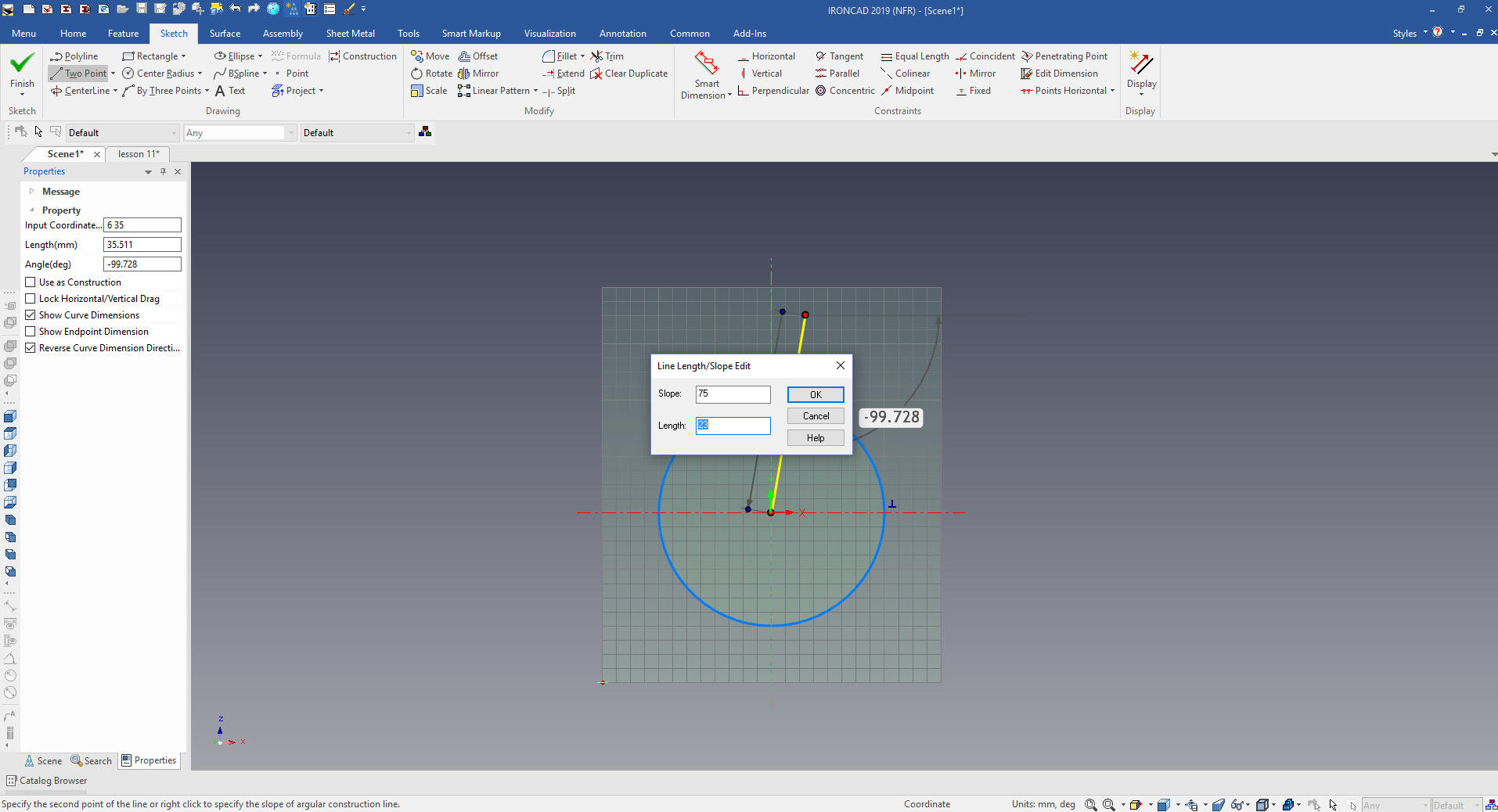
I
will create a line a set the angle and length to establish the
center for then 12mm circle. I show these steps because I do
not sketch like the Solidworks clone users.
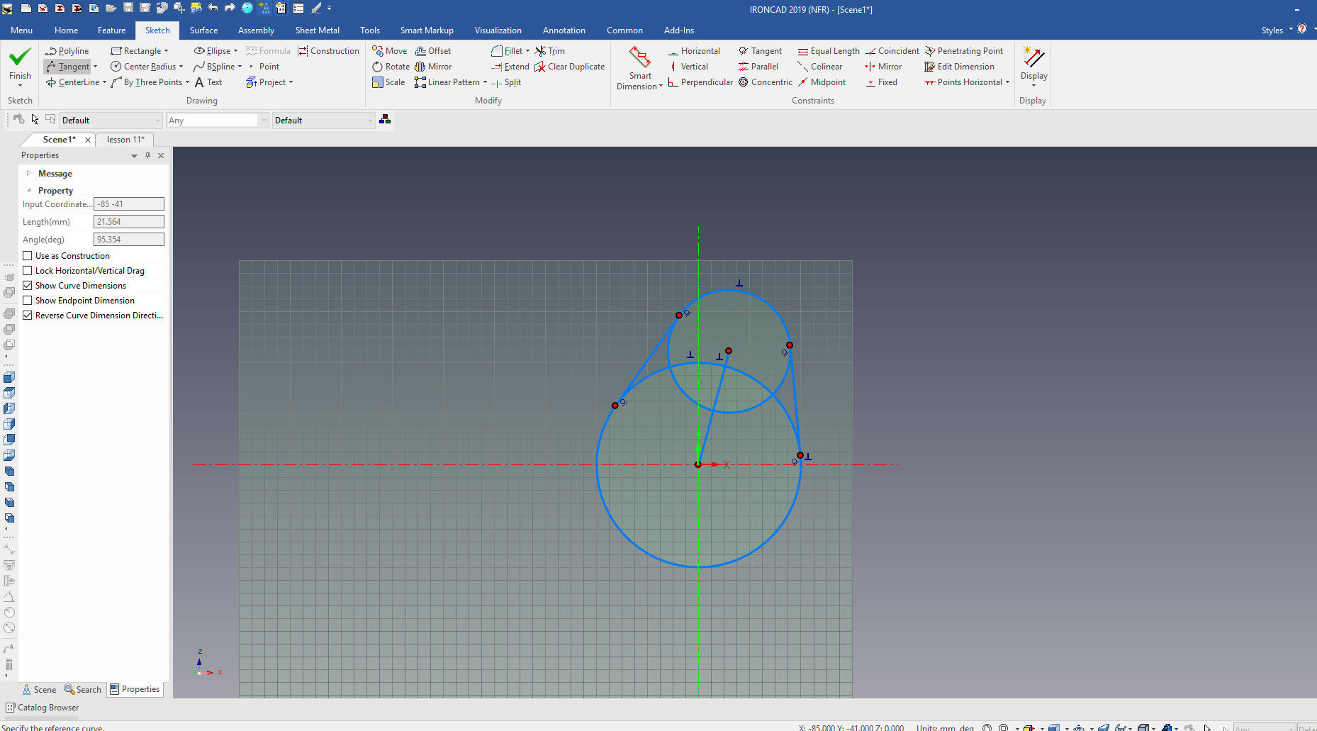
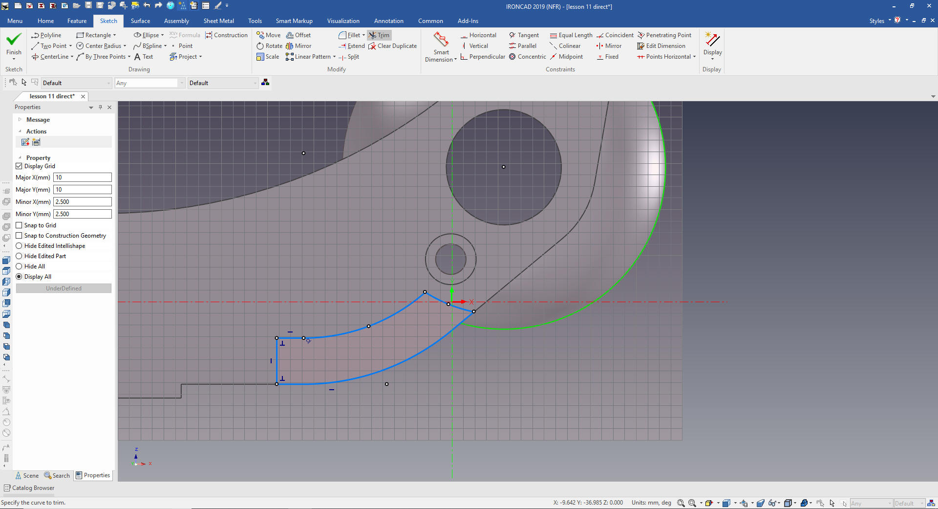
I will
now create the 12mm circle, put in the tangent lines.
I will trim the lines and rotate copy the entities.
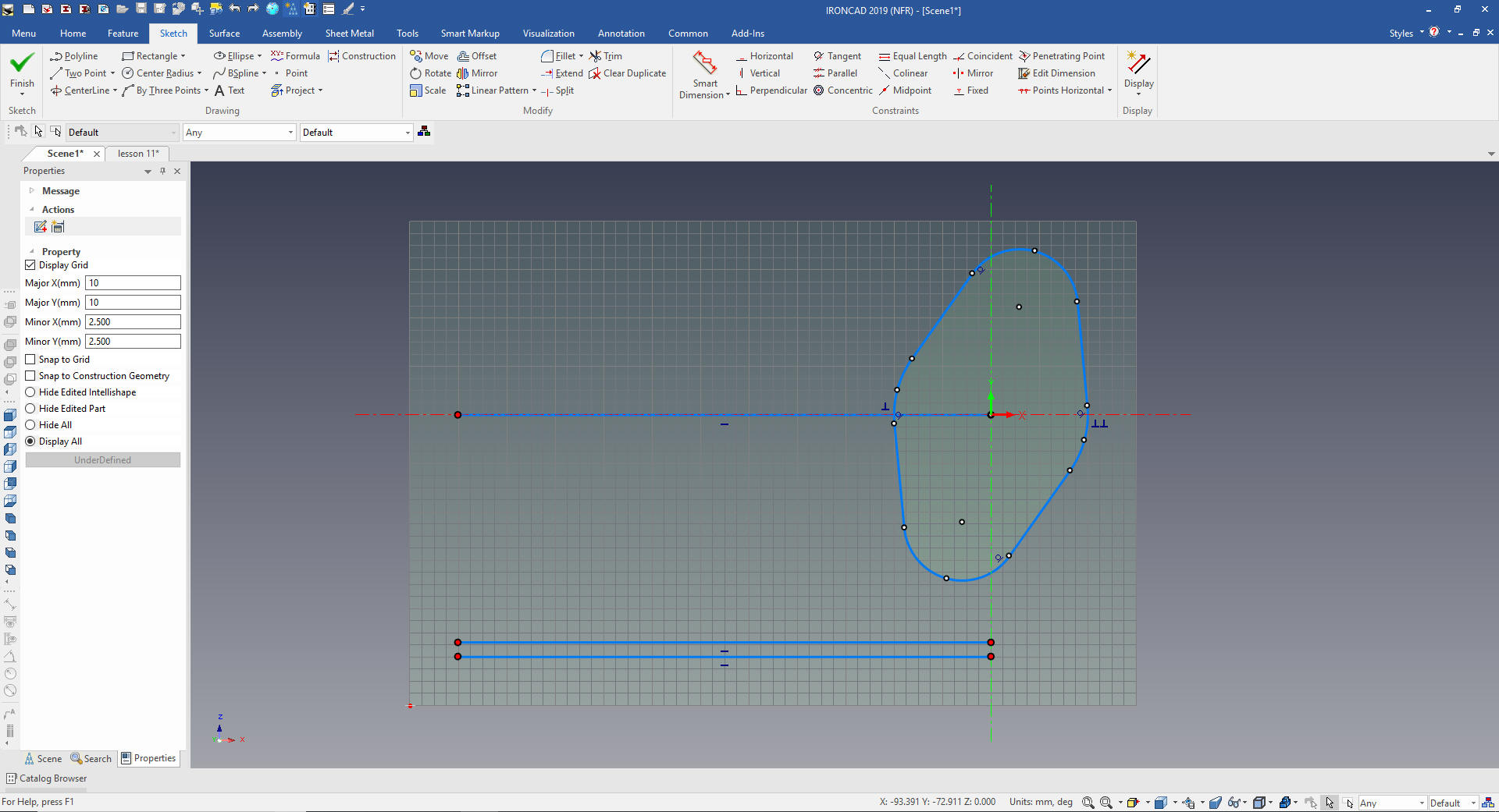
We create a reference 110mm horizontal line from the center and
create some offsets for the rest of the graphics.
We extend the diagonal line to the mating line.
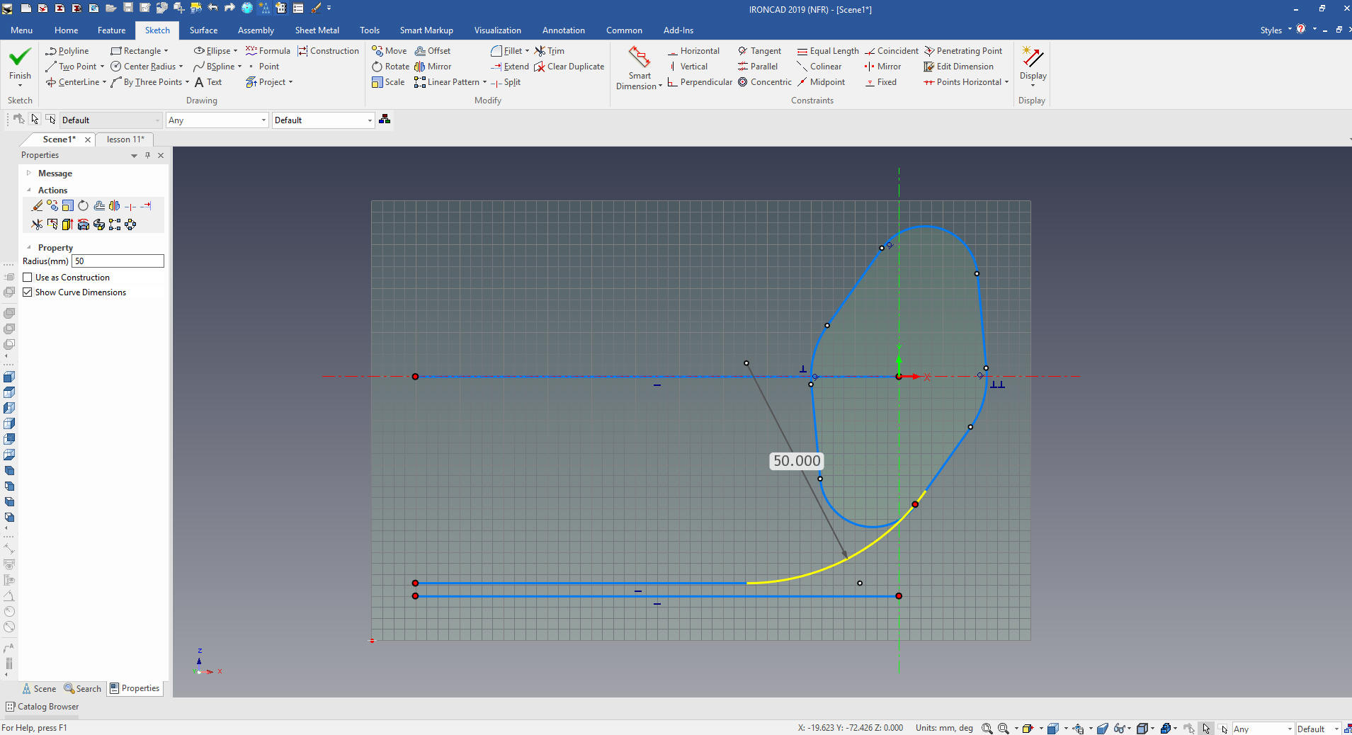
We are going to put in a 50mm radii
since it is not a mating face and will not matter.
I have seen three other Solidworks
clone users define a radius using tangent to an arc, it results in a
arc that goes out 3 places and looks like the designer didn't think
it through, LOL. Tangents do not exist in the real world, once this
is done there is no way to inspect it.
Sadly with CNC and non-contact inspection
standard drafting standards have been thrown out the window. We now
have a bunch of CAD jockeys that have no idea of what parts should
be based. All the draftsman are gone so we are entering a new
world.
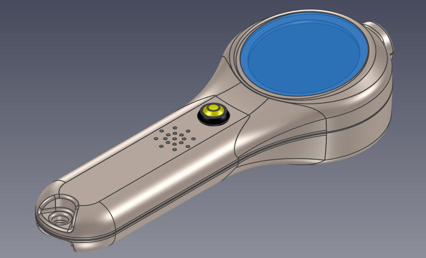
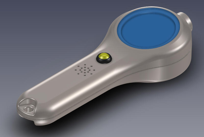
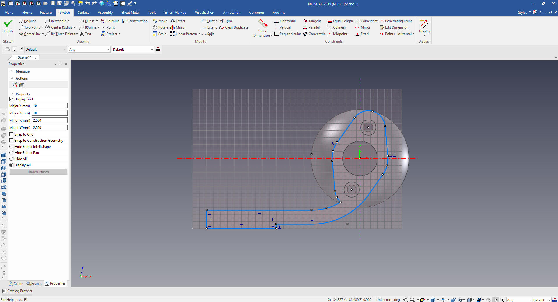
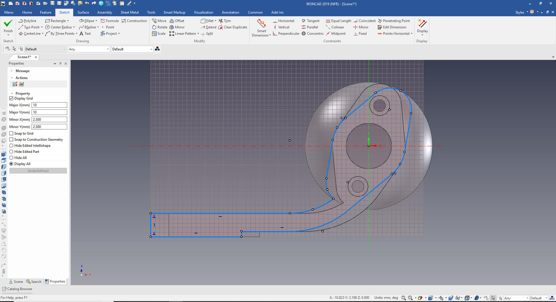
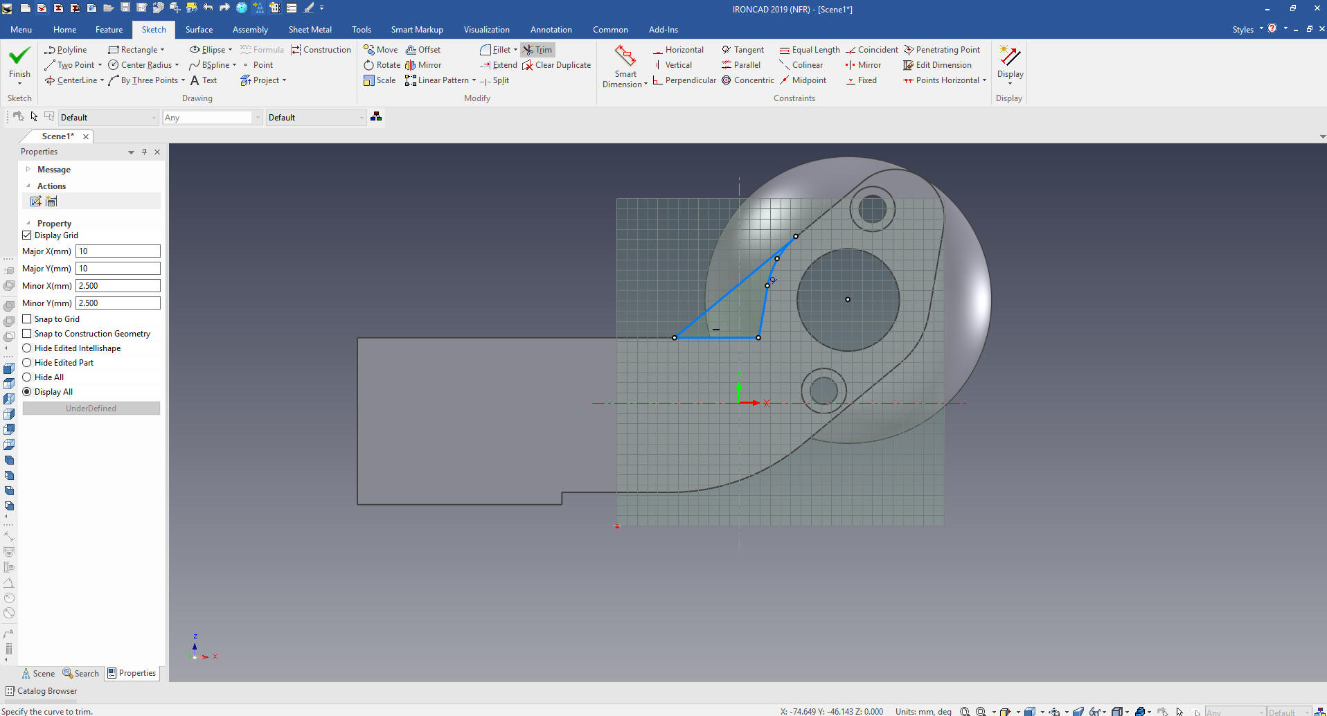
I sent the
image on the left to a customer and the product manager wondered what the lines
were. I realized that the tangents are only something, we as CAD
designers, know about. So I sent her the image on the right without
the tangent lines shown, she completely understood.
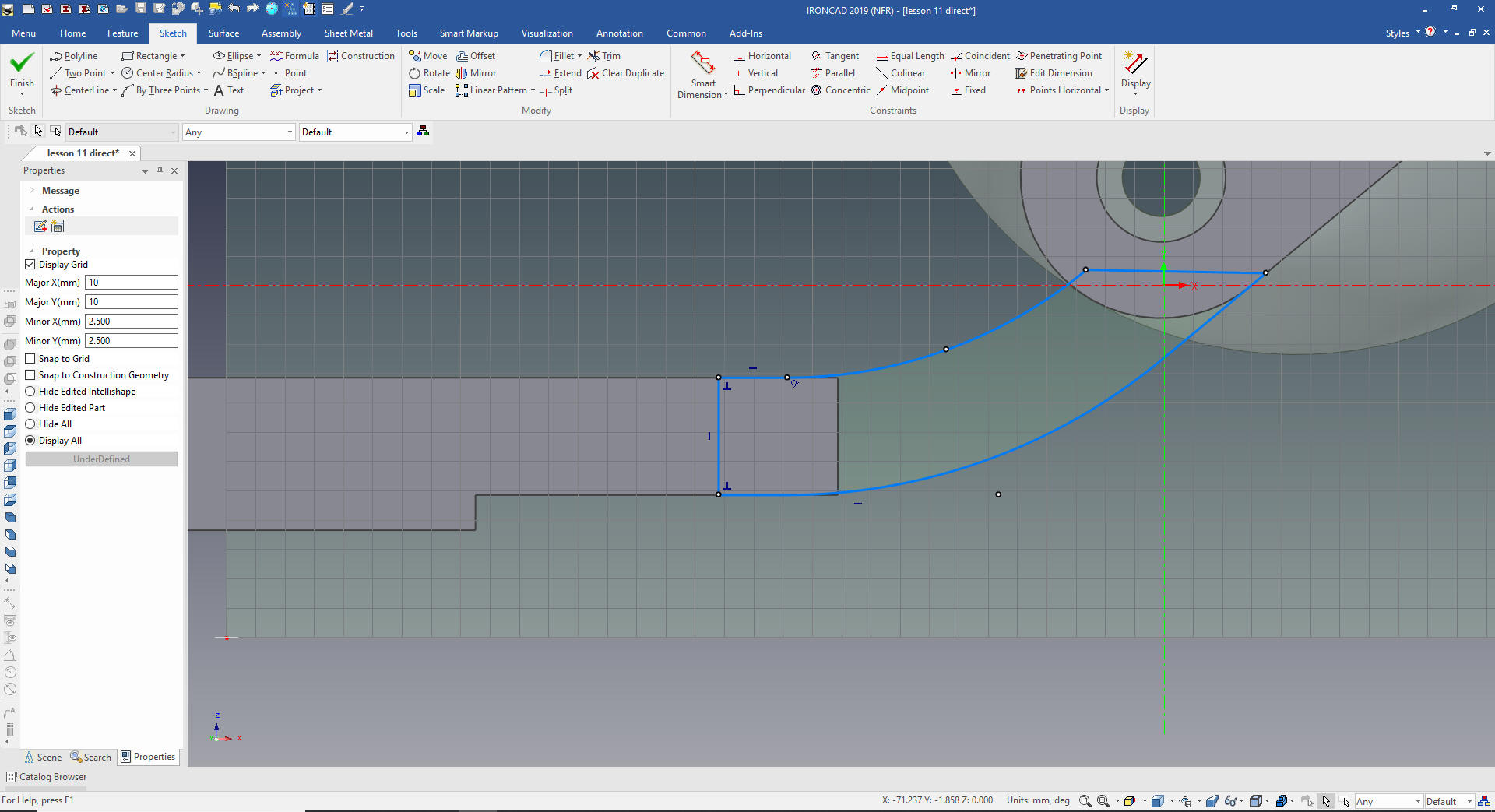
I offset the arc and line 10mm and offset the
50mm line and trim and add the block in back. Notice there are no constraint dimension.
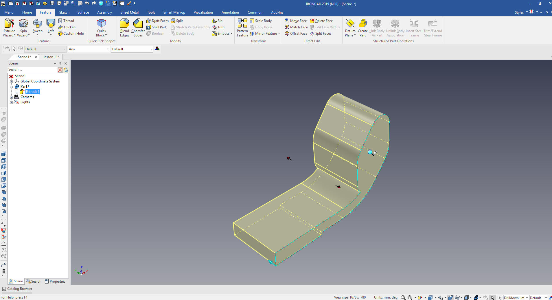
We select okay and it automatically creates
our extrusion. We set the direction and we are ready for the next
step.
I
will turn on the catalog, I usually use it hidden but we are going
to use drag and drop for the rest of the part.
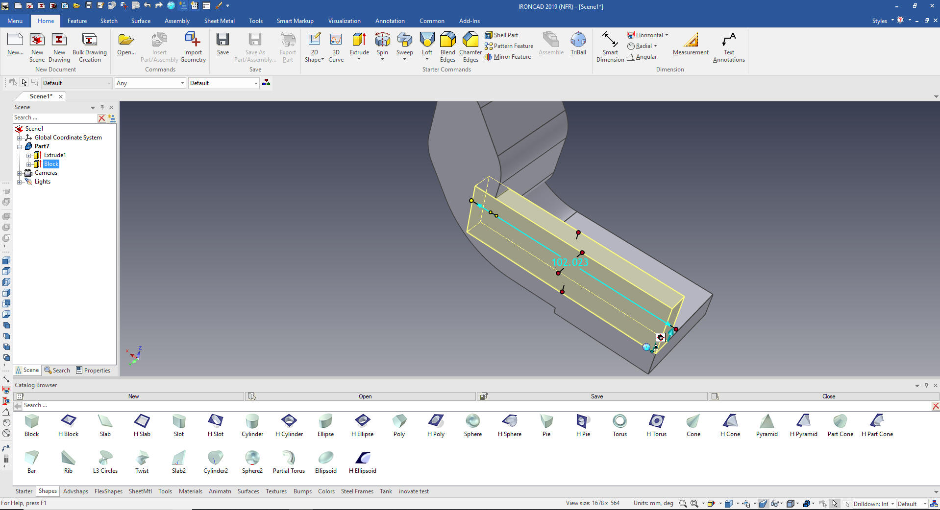
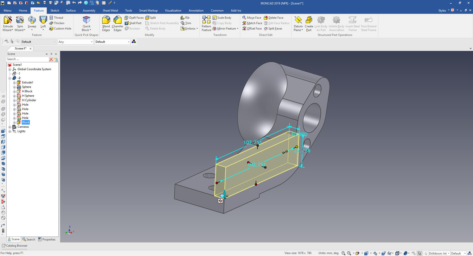
I drag and drop a block on the back of the
part and size it.
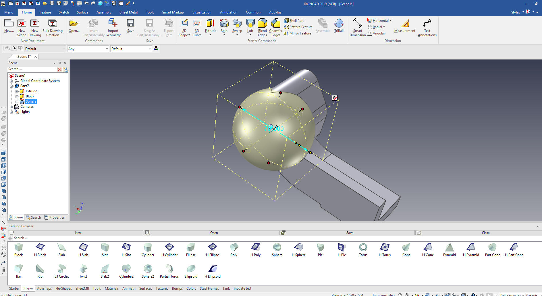
We
drag and drop a sphere to the center of the boss and size it
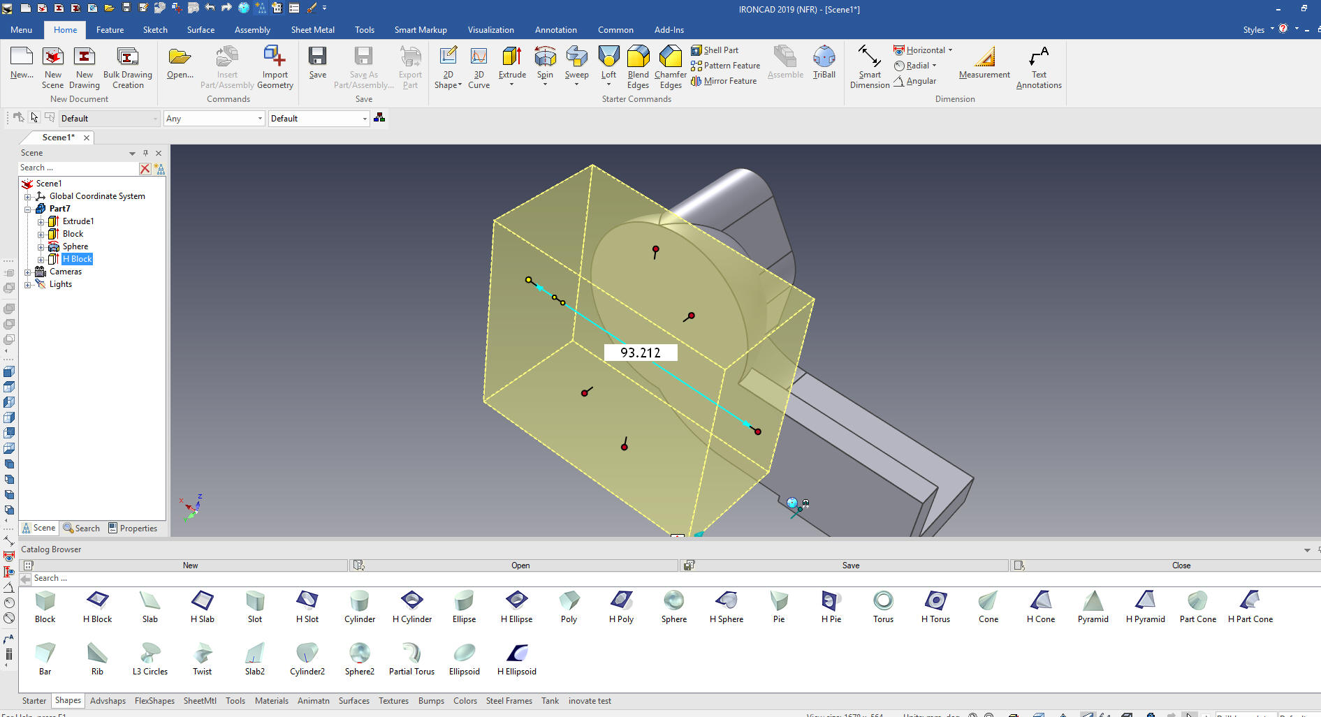
We
drag and drop a hole block on the lower face of the part and size to
trim the sphere.
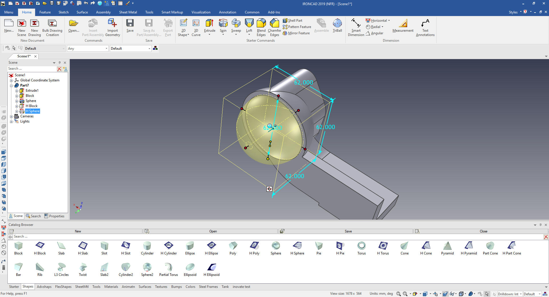
We
drag and drop a hole sphere to the center of the sphere and size it.
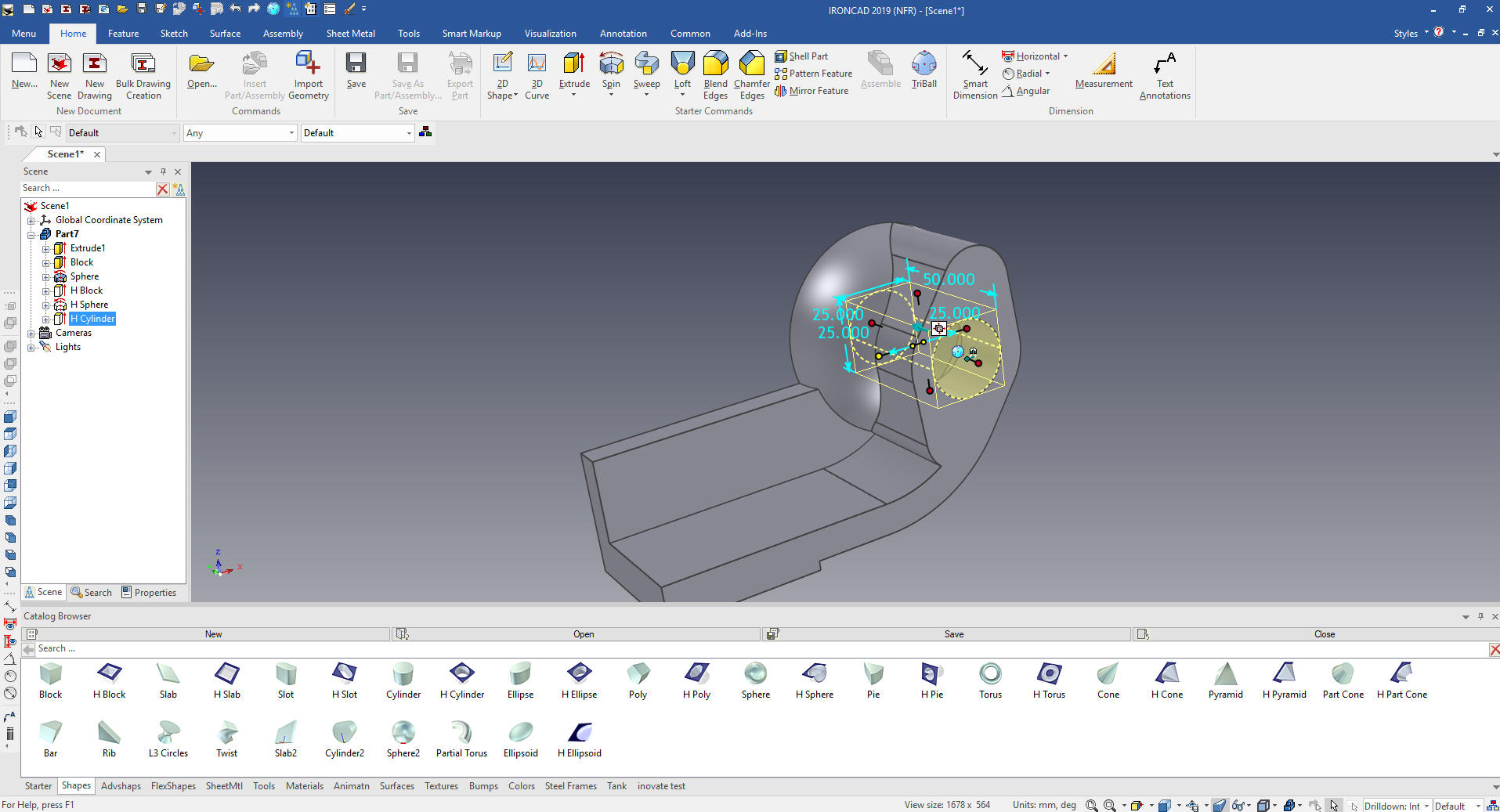
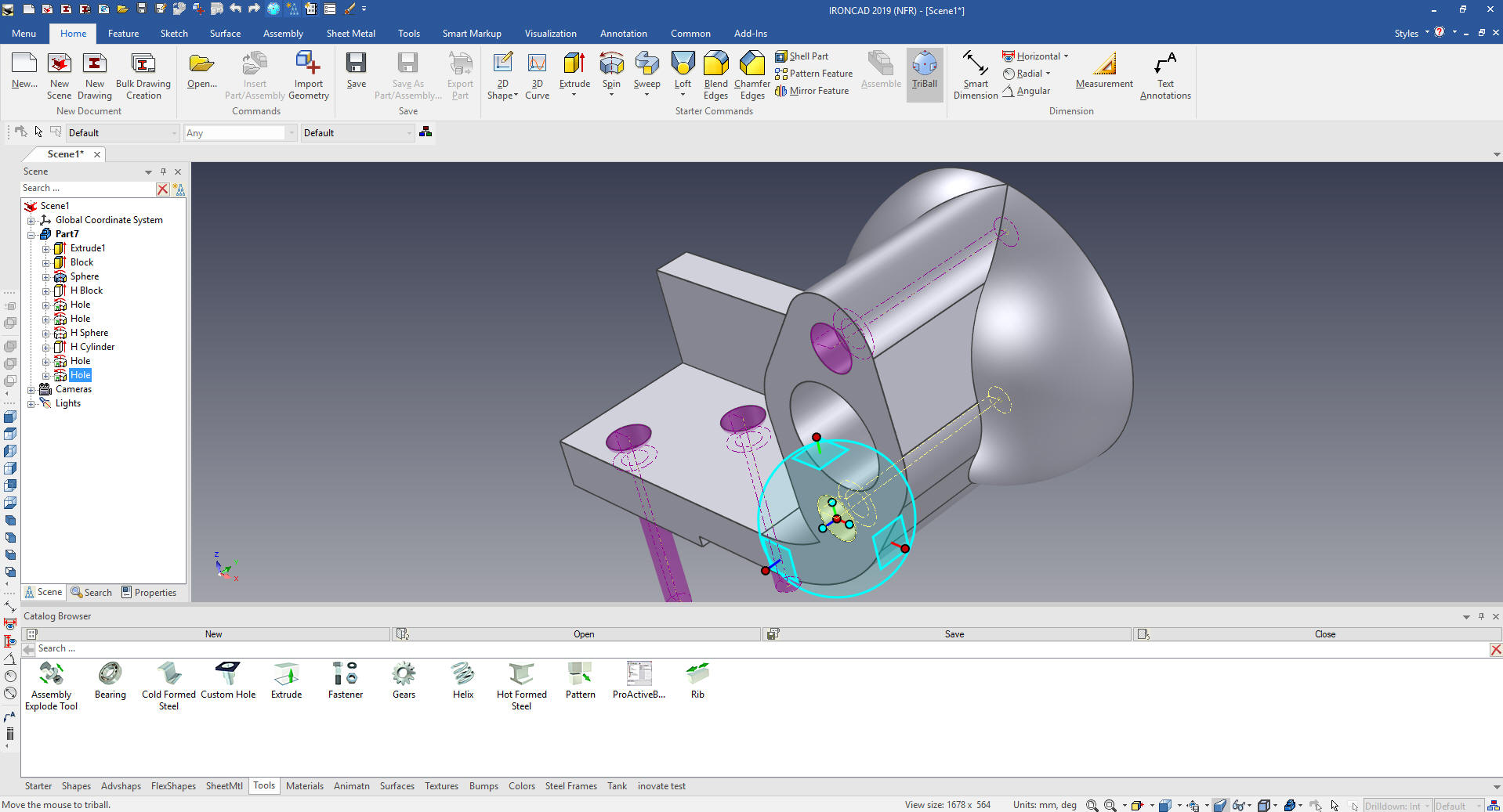
Now
for the holes. We will drag and drop a hole cylinder to the center
of the box and size it.
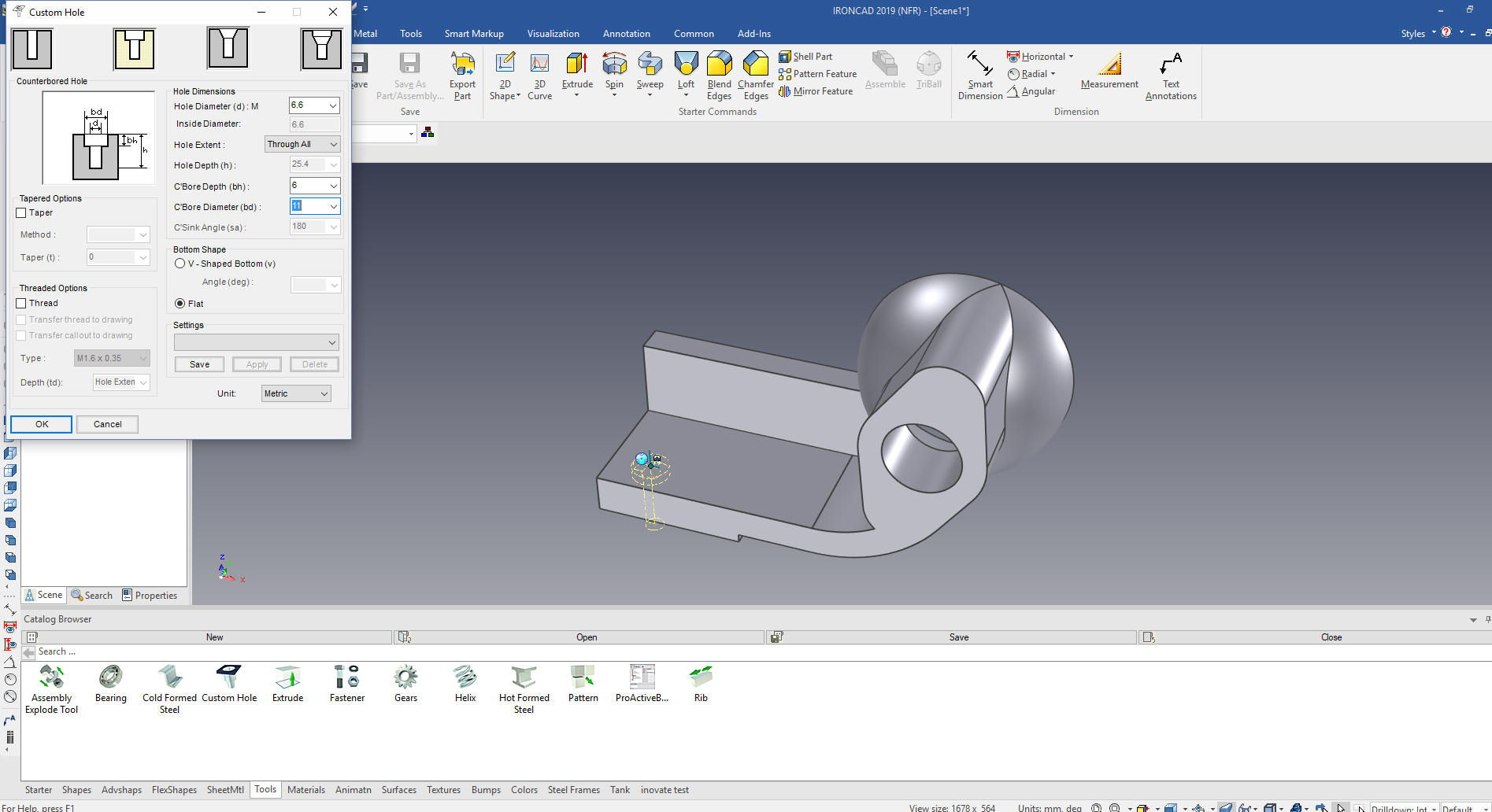
Using
the custom hole feature from the tool catalog we drag and drop the
hole on the face of the part.
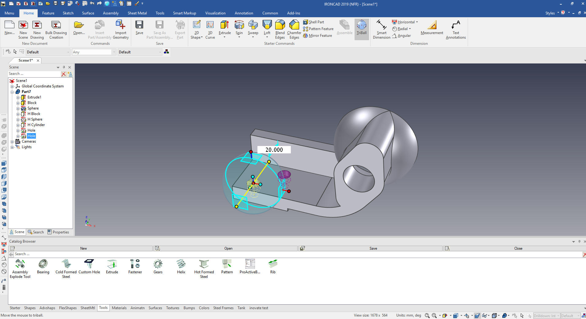
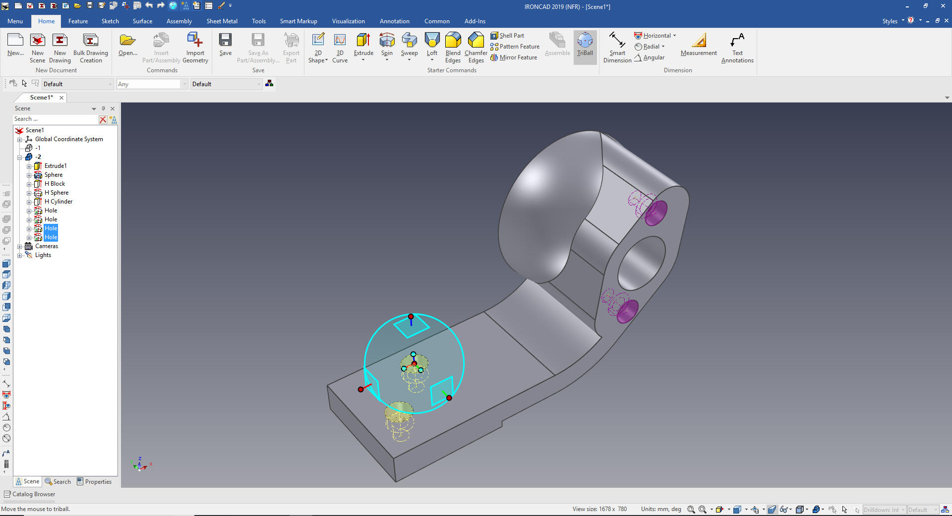
We
then locate the hole using the Triball and again using the Triball
we locate and link the other hole. The other hole is shown in purple
indicating it is linked.
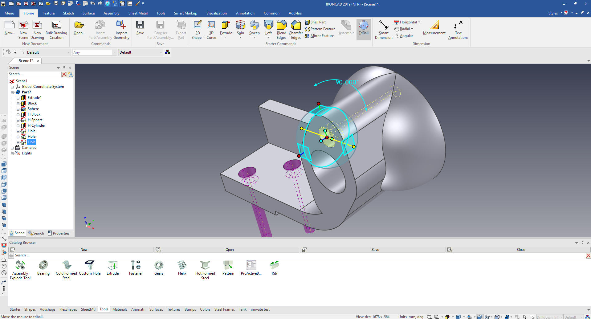
Using the Triball we link the hole to the
center of the top radius and rotate 90 degrees.
We again use the Tribal to locate and link
the bottom hole at the center of the lower radius.
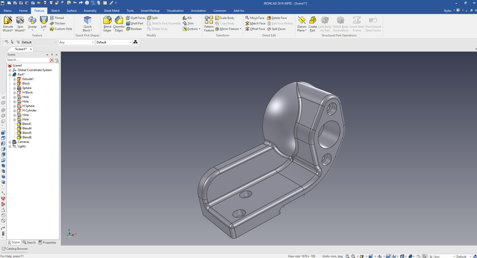
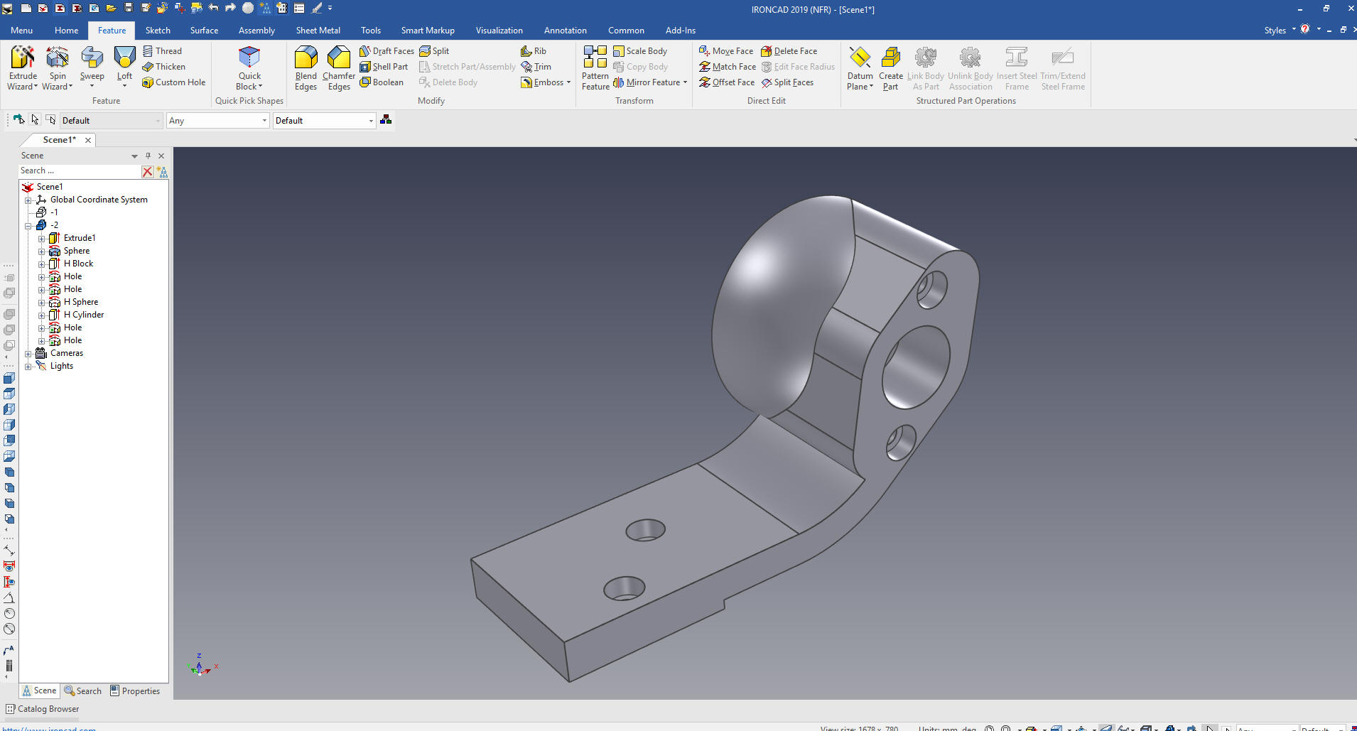
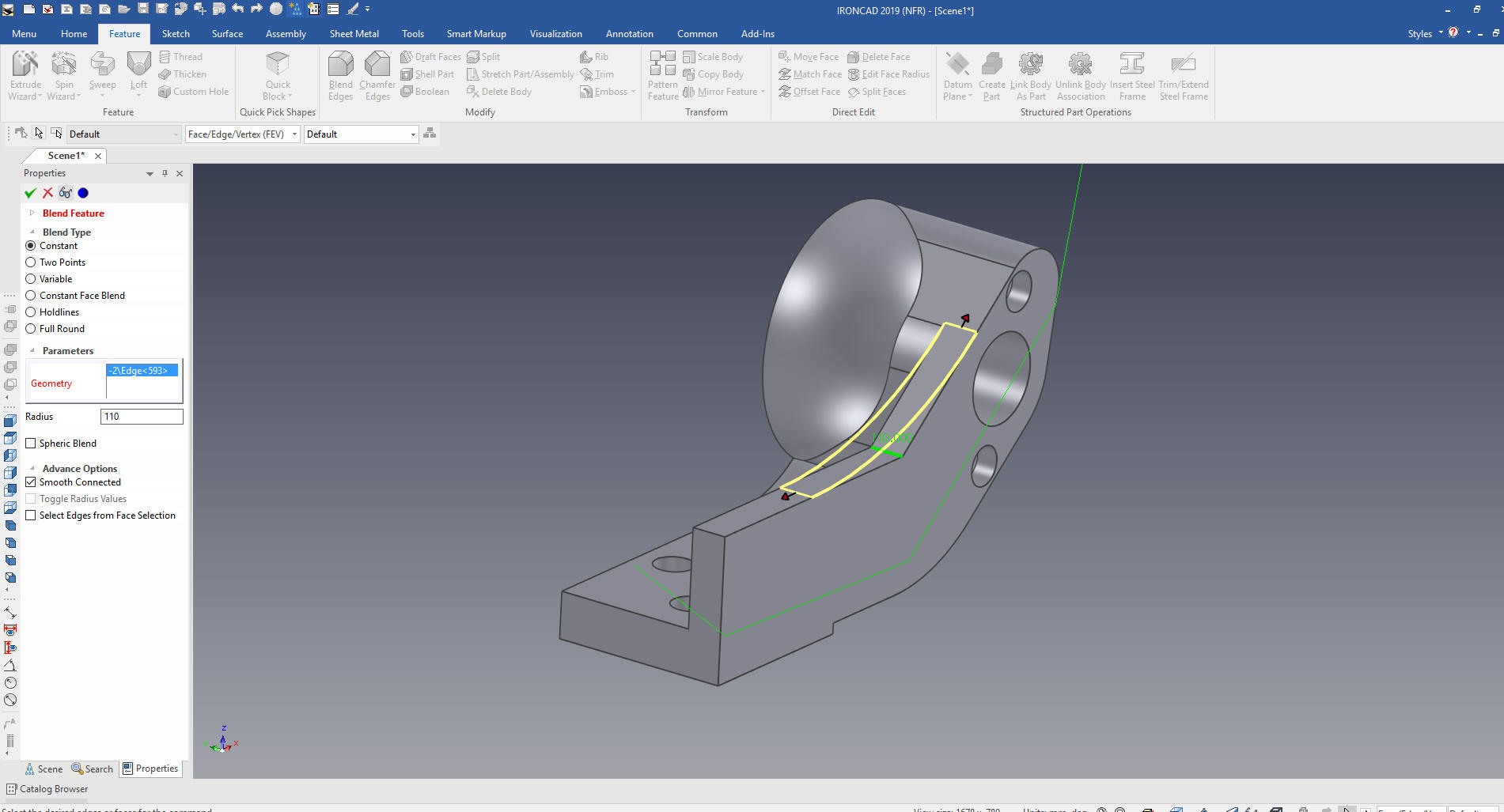
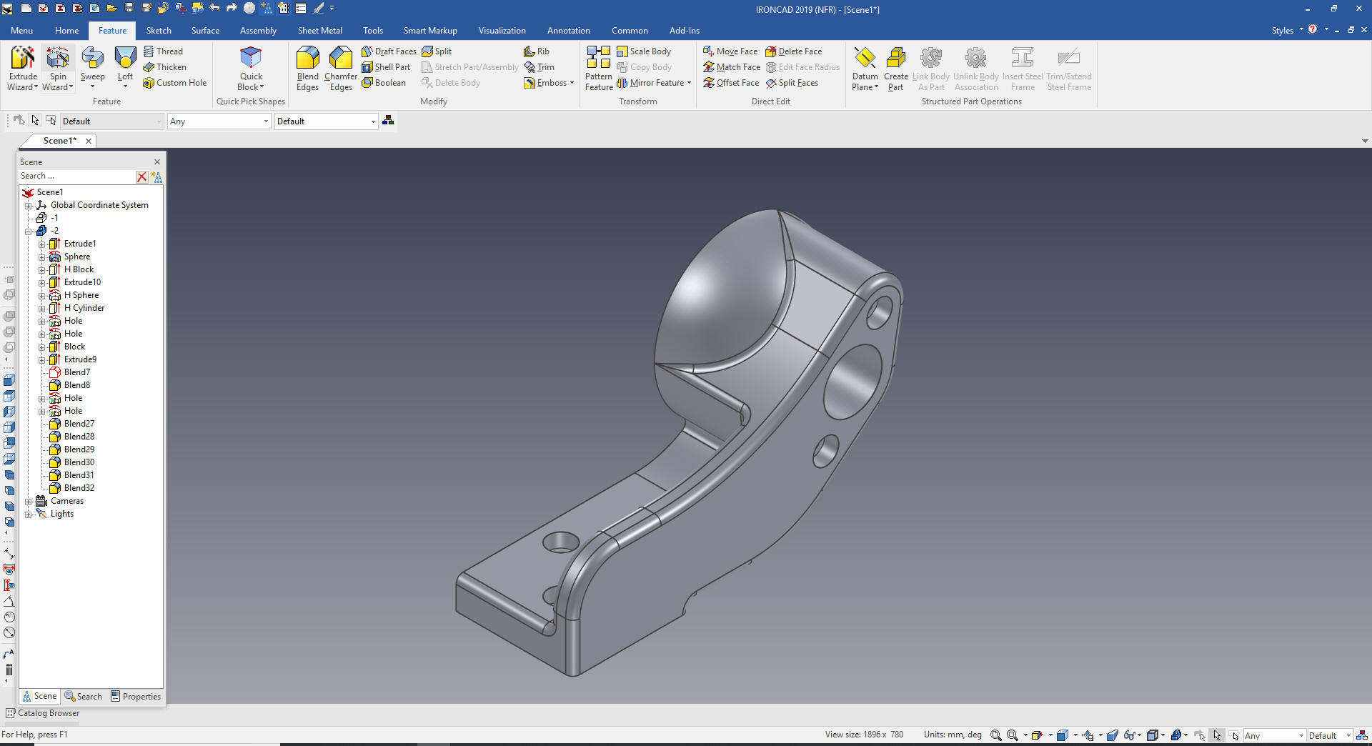
We are now ready for the blends. I will close
the catalog. I am a bit picky with blends many times if you
haphazardly pick faces the blends come in incorrectly.
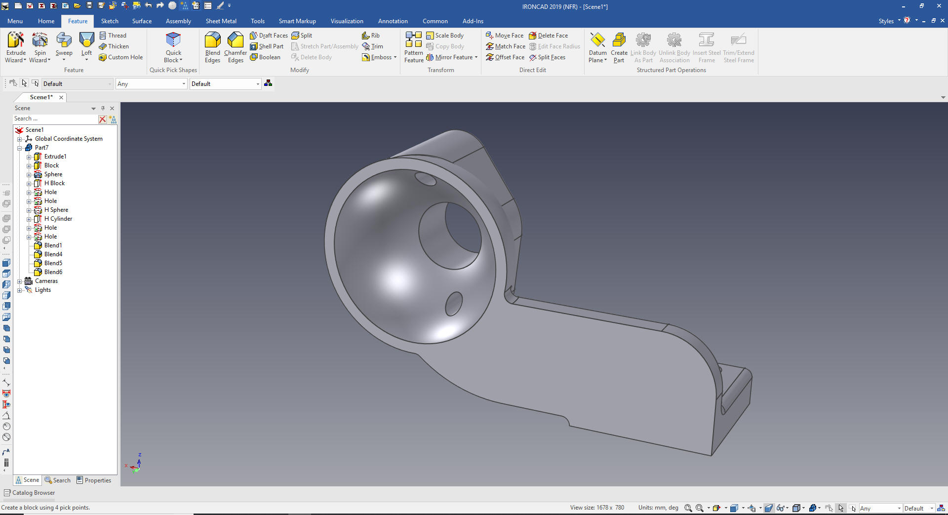
Here is the view from the other side.
Now to create a similar part -2
First thing we do is copy
and paste the part. I renamed
the first part -1 and the new part -2 and suppress, we can do this
because IronCAD is a single model environment.
We delete the
blends it is much easier to reinsert them than edit them. We also
delete the block.
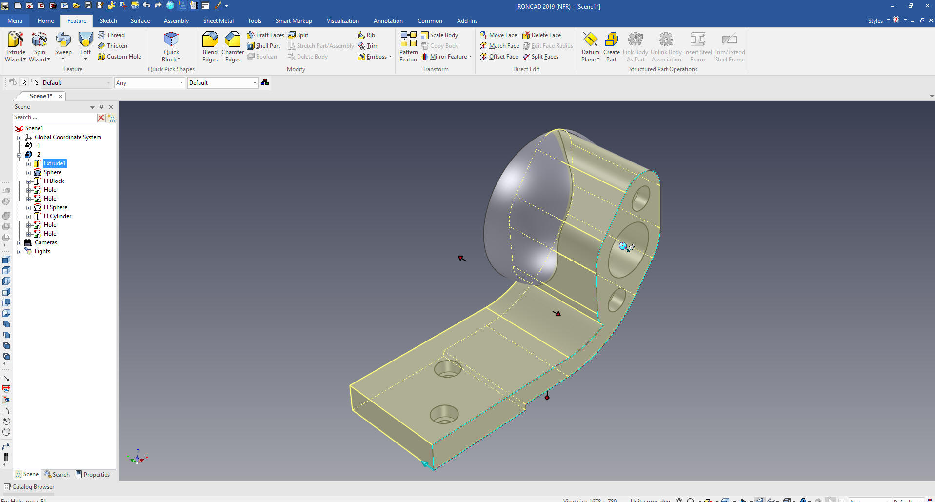
We select the main extrusion. You can see the sketch, it an
integral part of the feature.
We
select "Edit Cross-Section"
We
edit the sketch
Select okay
and we are for the next steps
We use the Triball to move the holes. The Triball is used
throughout the design process. You can see the other linked holes
referenced in purple.
We drag and drop a block, locate and size it.
Using the Extrude Wizard create the next
sketch plane and set to add. The Extrude Wizard is one of the more
use features especially when creating mating parts. We are not going
to create an arc tangent here we will put the blend in in the next
step.
We select okay and the extrusion is
automatically made we just size it and add the blend.
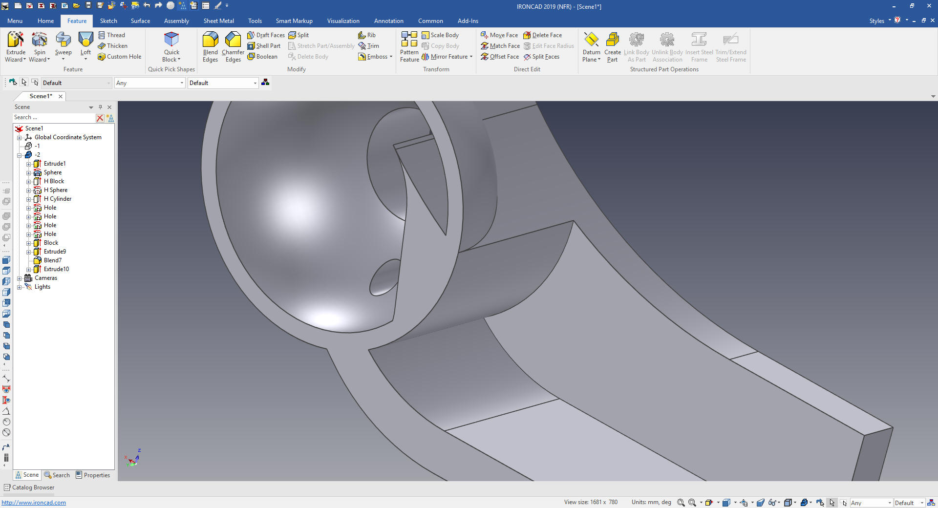
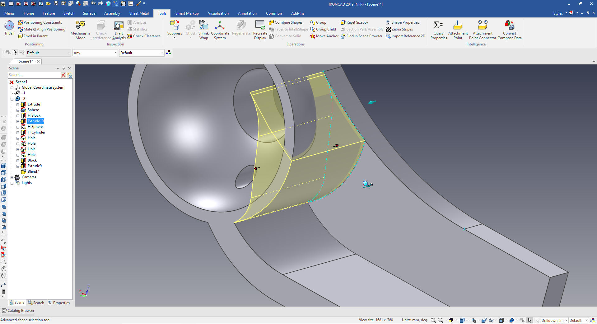
We now need to fill the small space on the inside. Again we use
the Extrude Wizard.
We select okay and size the extrusion. You can see the extrusion
is in the sphere.
We just move the extrusion above the hole sphere in the history.
We are ready for the blends
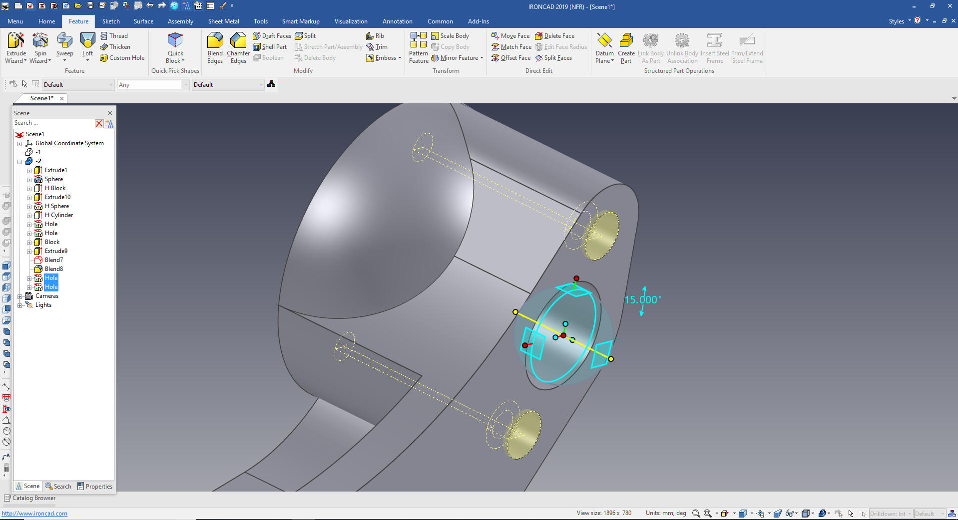
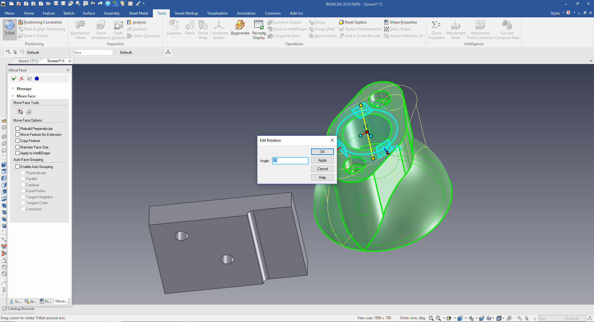
Almost forgot the holes. We select the holes and turn on the
Triball, we can move the Triball only if we hit the space bar, I
move it to the center of the main hole. I rotate it the 15 degrees.
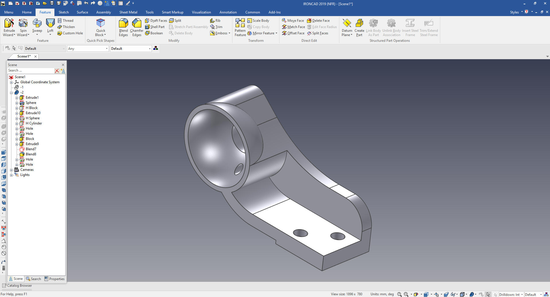
Add the blends and we are done.
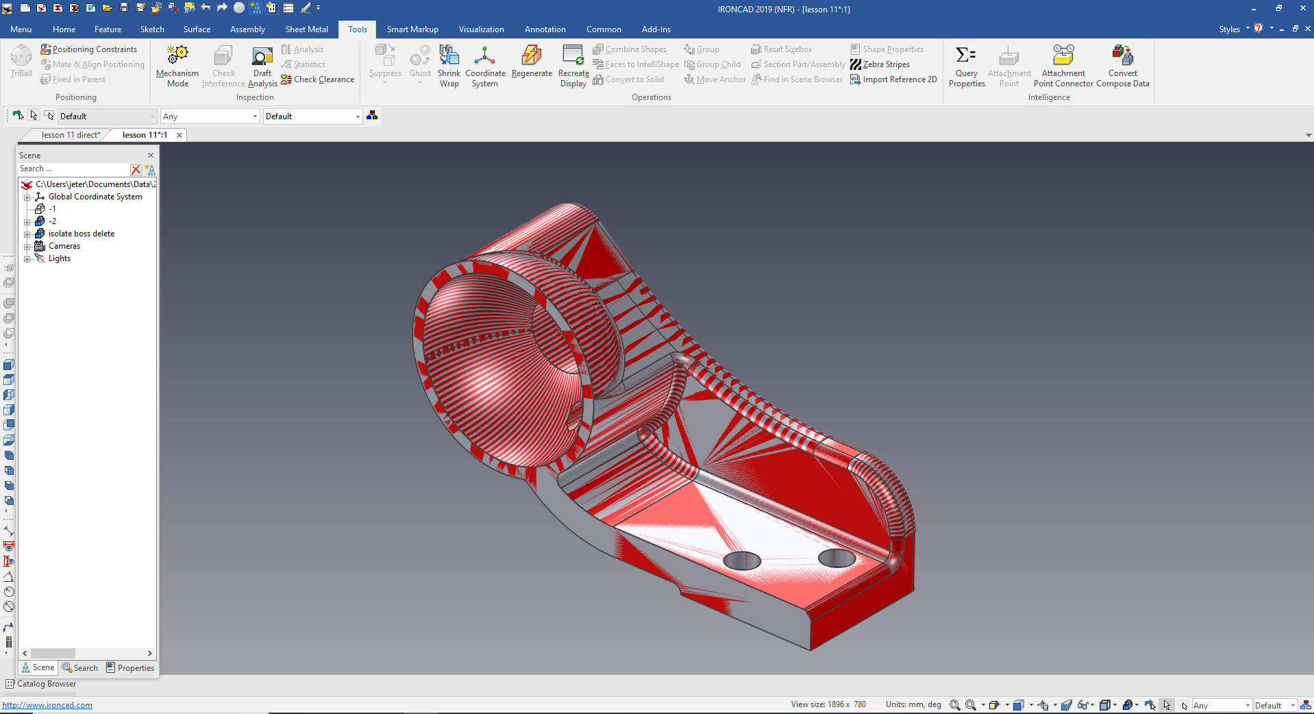
DIRECT EDIT MODIFICATION
I thought it would interest you to make the changes by direct
edit. Now this is a very simple model and you could easily recreate
with just using features. But I thought this would be fun.
IronCAD is the only integrated history/direct edit based system. NX
and Solid Edge have given it a try but fall far short due to their
dependence on previous history so let's take a look.
You can see in this article the extensive experience I have with
direct edit.
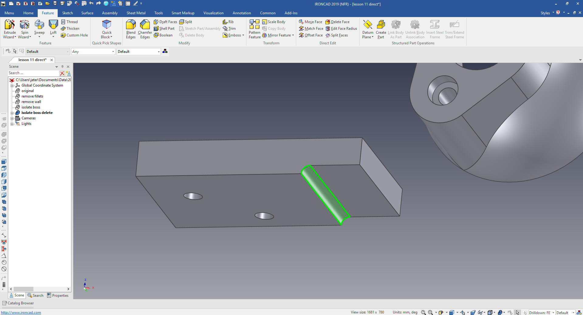
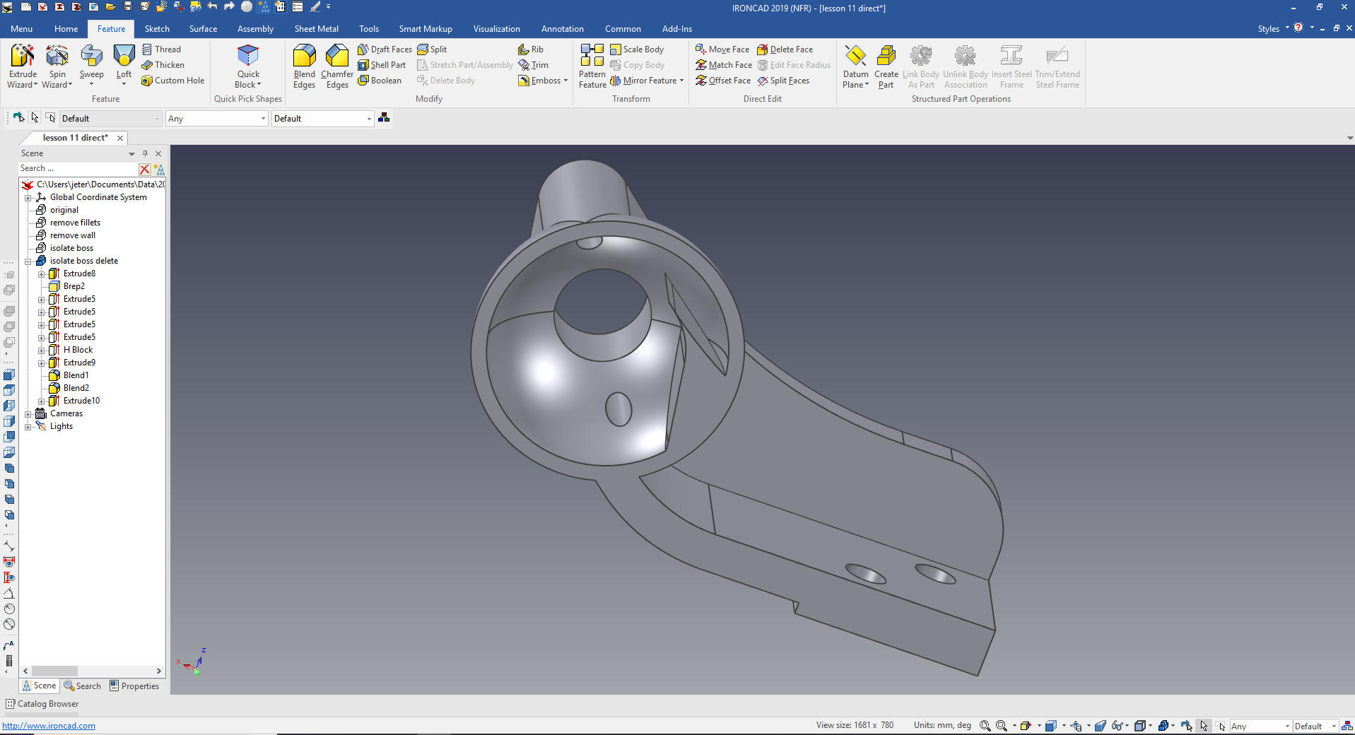
I have exported -1 as a STEP file. First thing we do, like when
just modifying a part is to delete the blends. This may take a bit
of investigation. I found these were the first blends to delete and
the rest fell into place.
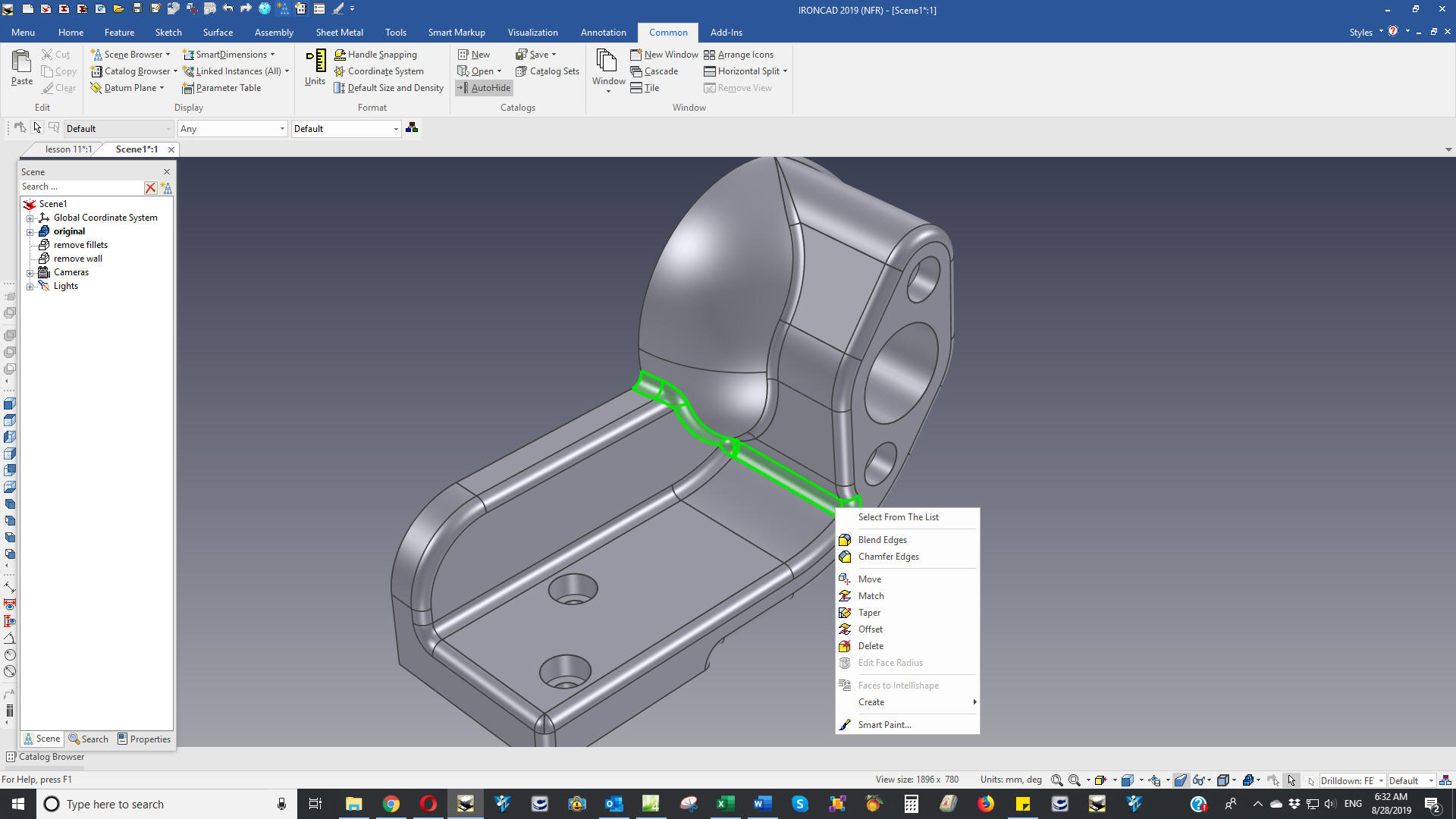
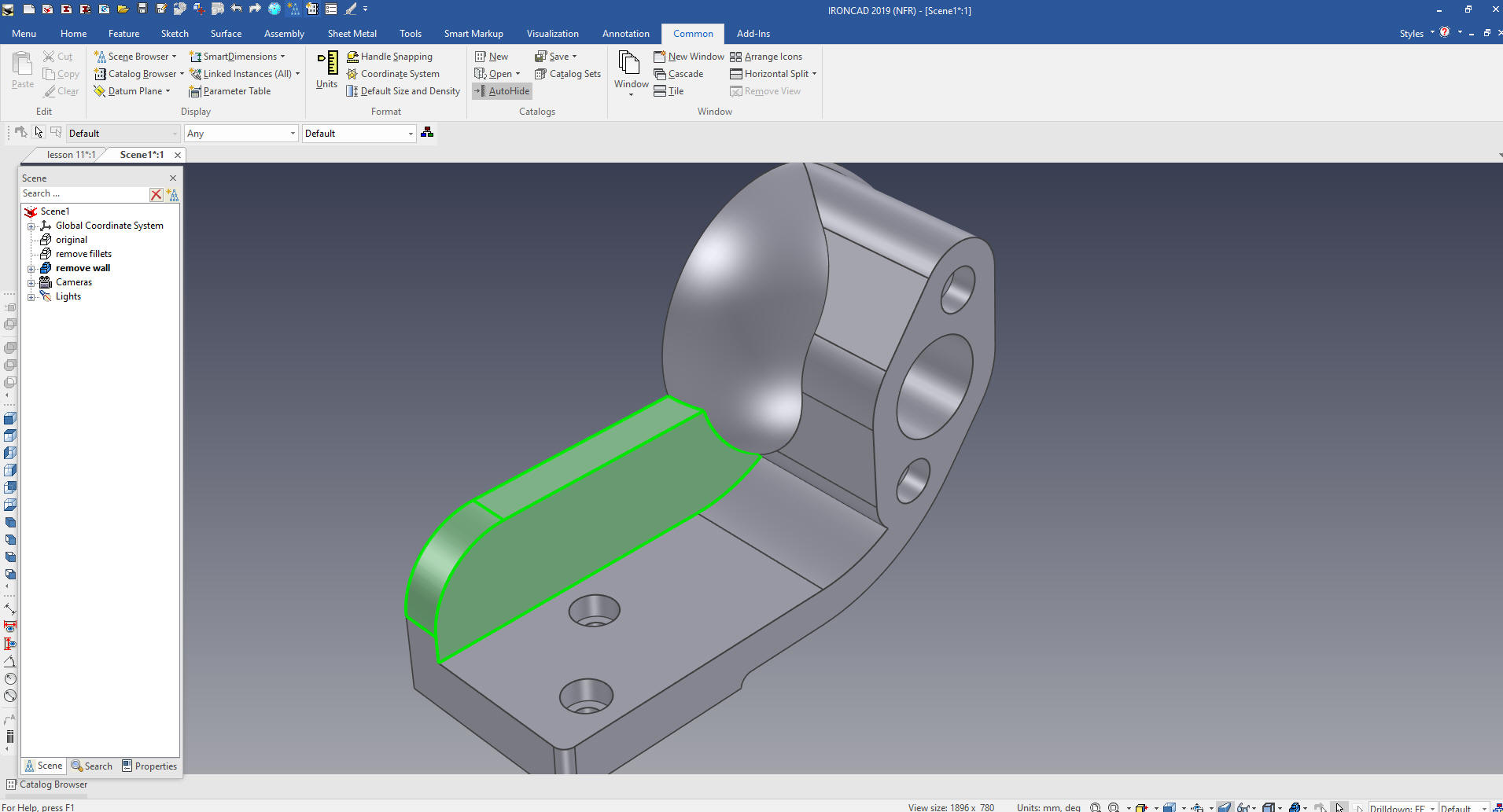
With that done we will delete the wall. We select the faces and
with a right click of the mouse button a dialog box comes up and we
select delete.
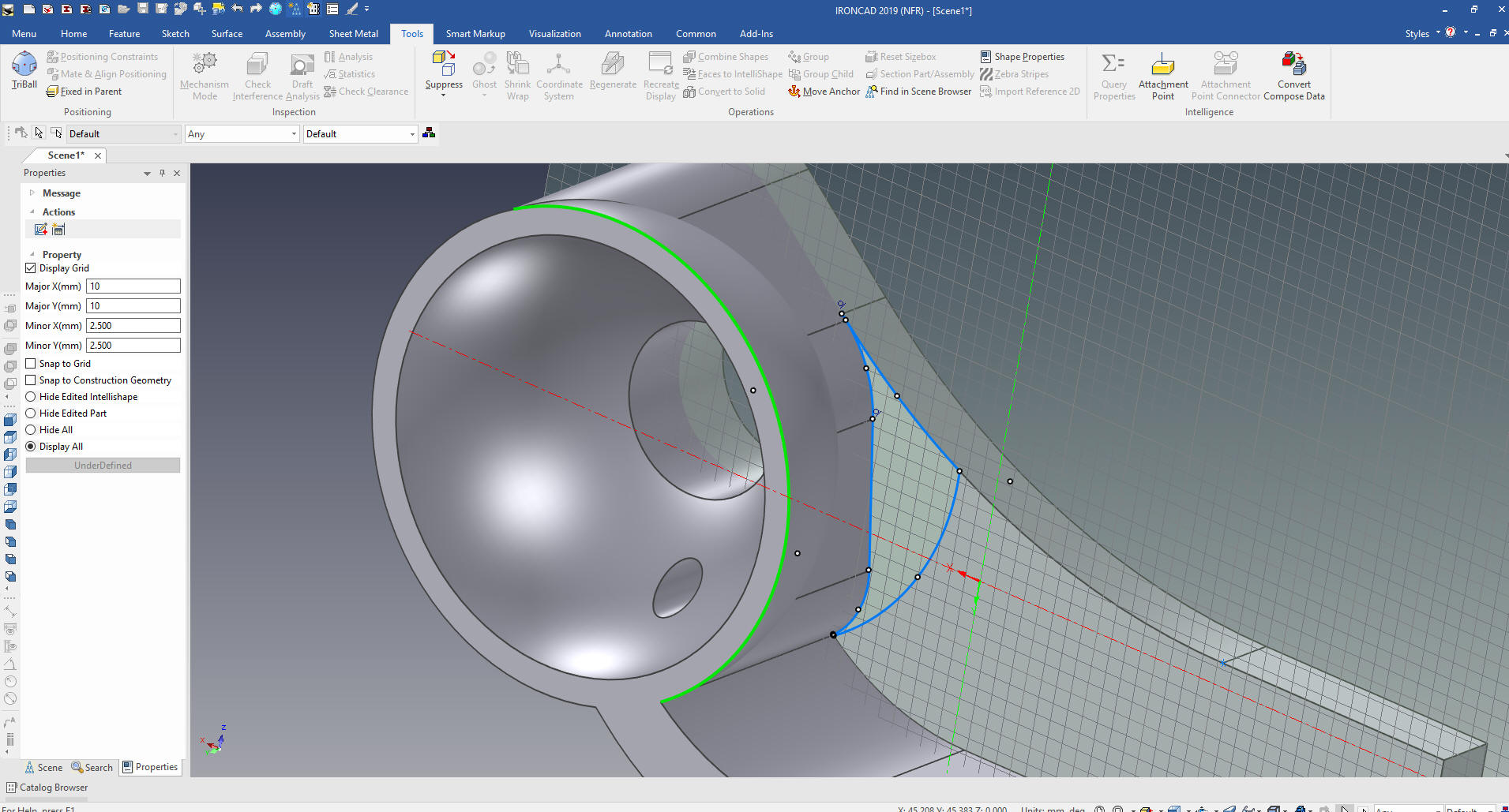
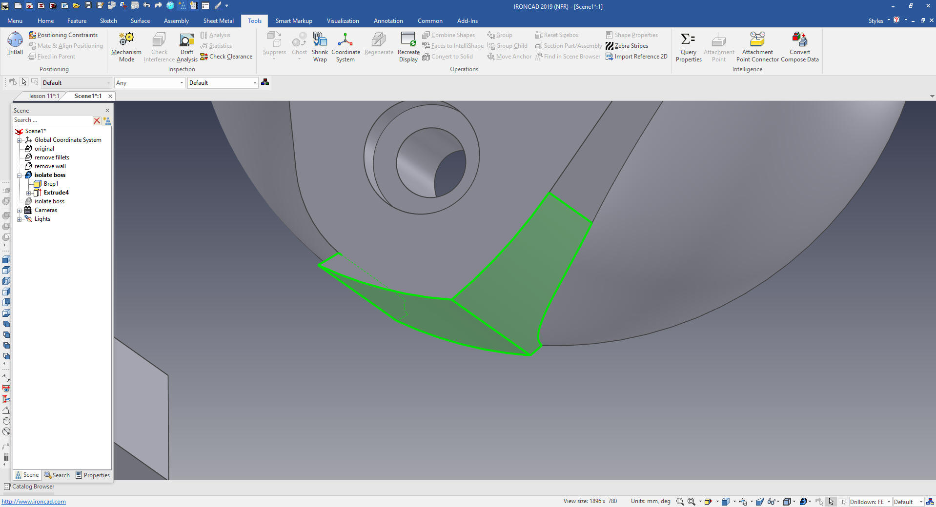
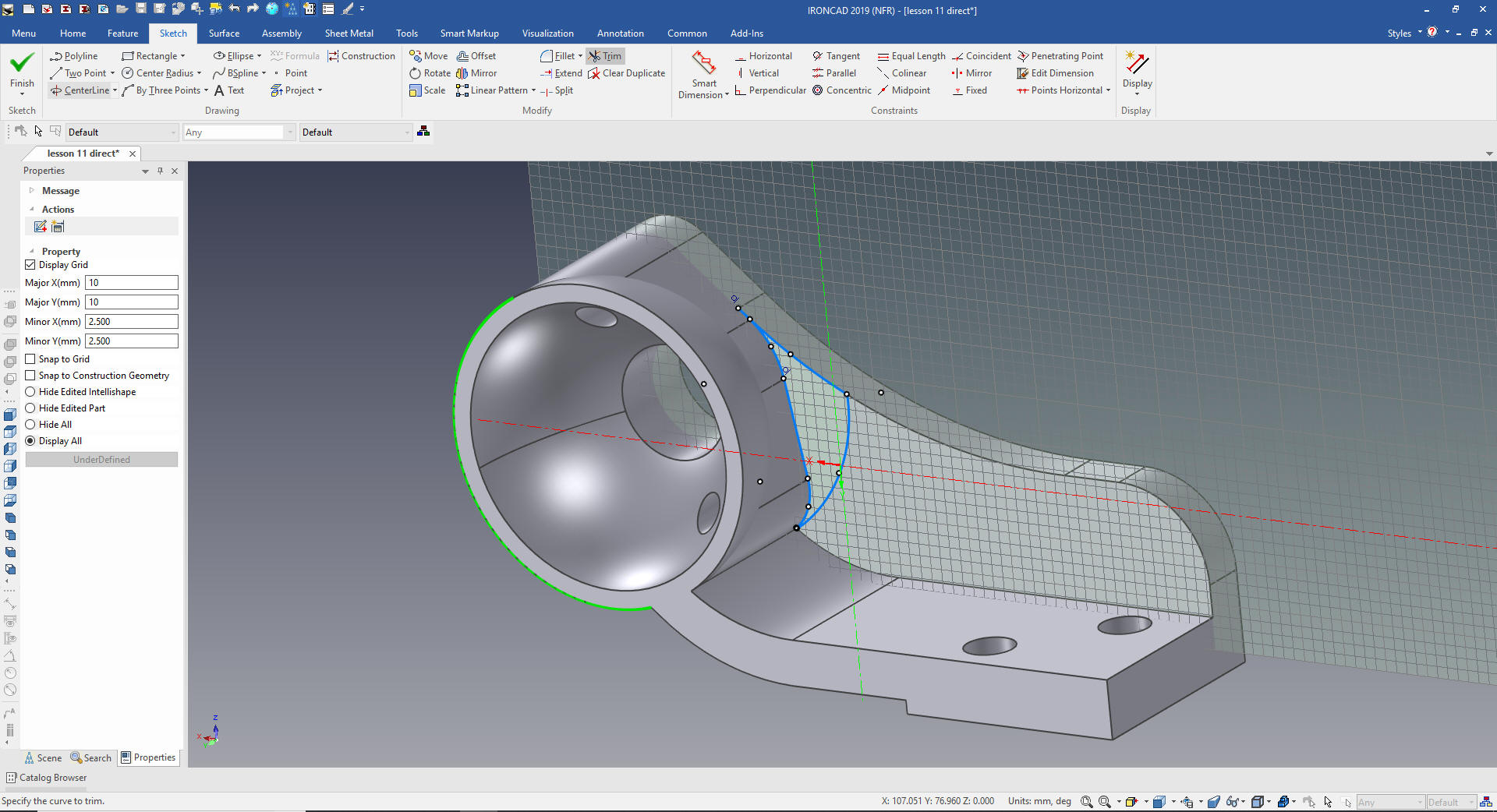
Now we have to isolate the boss and the spherical shape. You have
to study the part and do a few trials and errors until you come up
with the correct solution. I have created a sketch that will
minimize the extraneous features and of course move our selection
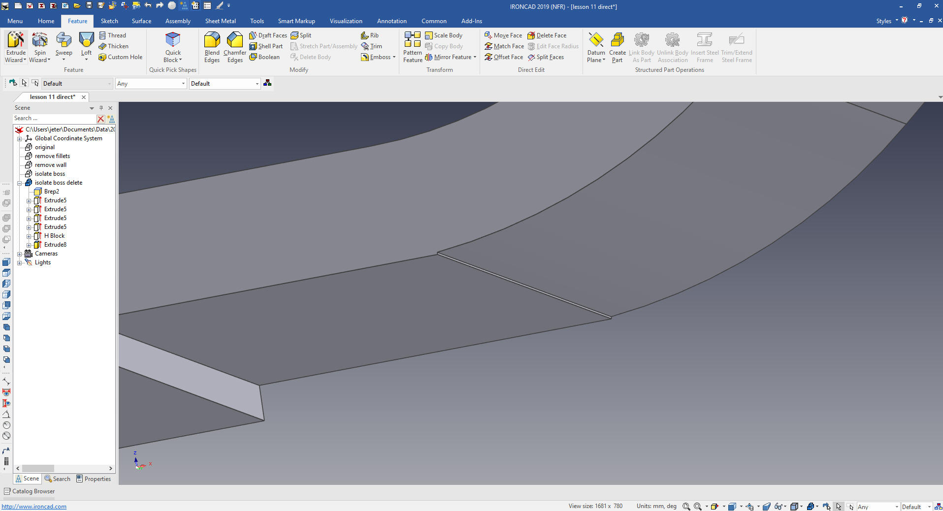
outside the blend tangent on the base.
We select the faces we want to remove and with the right mouse
button select delete.
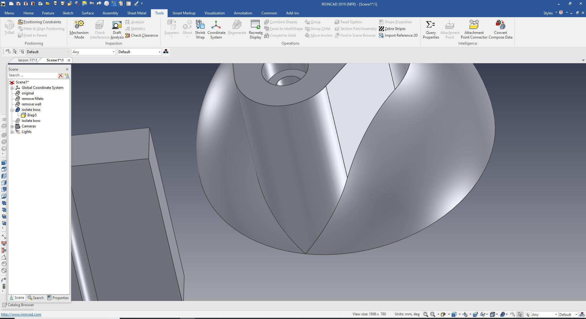
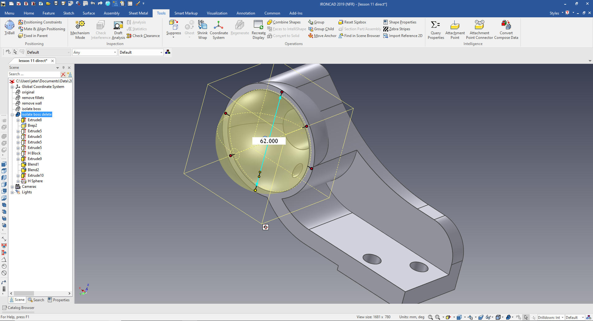
You now can see we are down to the sphere and boss.
Now we just window select all of the faces that make up the
sphere and boss and rotate 15 degrees
Now we have the feature oriented to the new position.
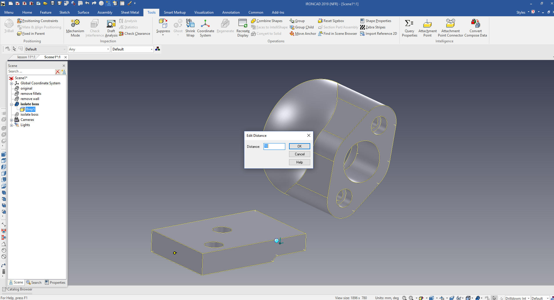
We move the back face 10mm. IronCAD has 4 different stages as you
click, first is yellow that indicates the assembly, then blue which
indicates part, yellow again that indicates feature than green that
indicates faces.
I only go down to feature to move the front face 10mm
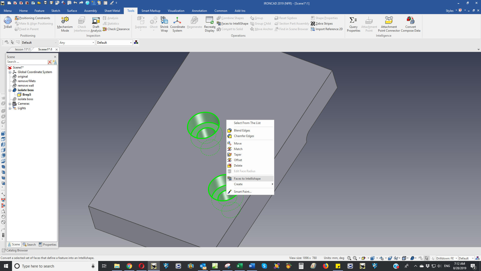
We now select the faces that make up the holes and we find we can
convert them to intellishapes. Many times you can take shapes
positive or negative and make them into editable features.
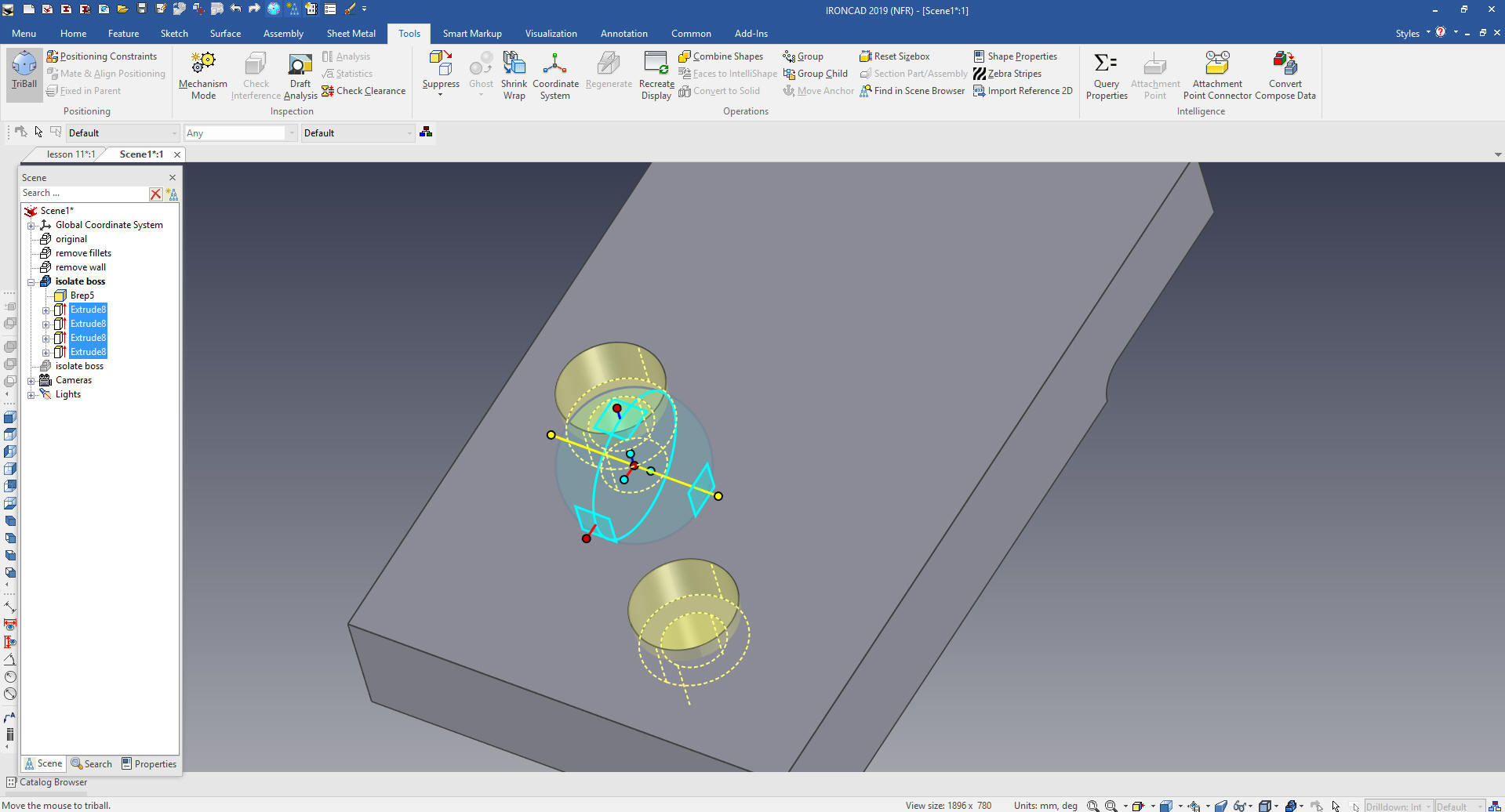
We will then move them into place with Triball
I want to move this face but I cannot with out it being altered
also I cannot delete it so I will have to drag and drop a hole block
locate and size it.
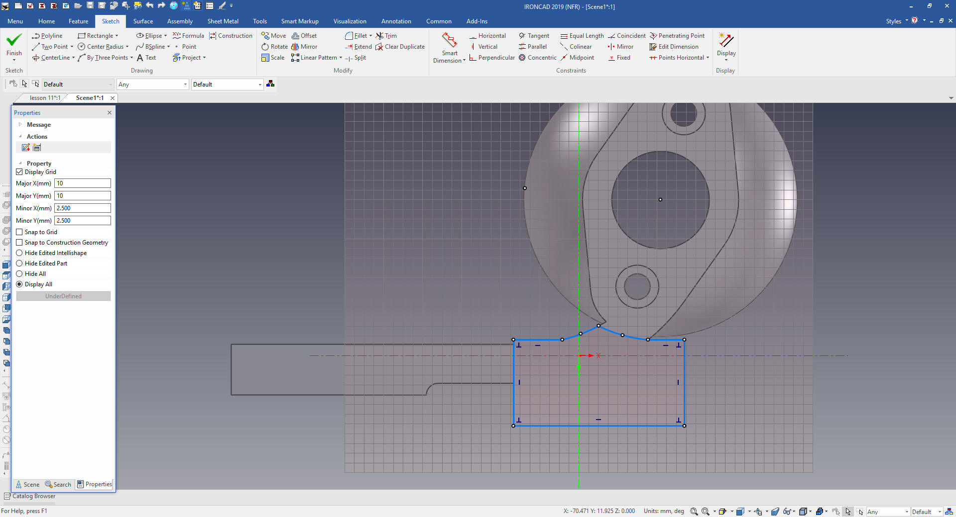
Now for the base. We will make the sketch. You can see the boss
sticks out a bit. Don't worry I can fix that later
We select okay and pull it into place. You can see the extraneous
feature that sticks out no problem we will suppress the new feature
an move the face back a few millimeters.
We just create a sketch and extrude and add the blends. Oops I
see we have a problem with a feature extending into the sphere I
think we can fix that by just editing the sketch.
Select okay and everything is fine now piece in the middle.
We create the sketch.
Size the extrusion and ooops another small problem
We just drag and drop a hole sphere and size it.
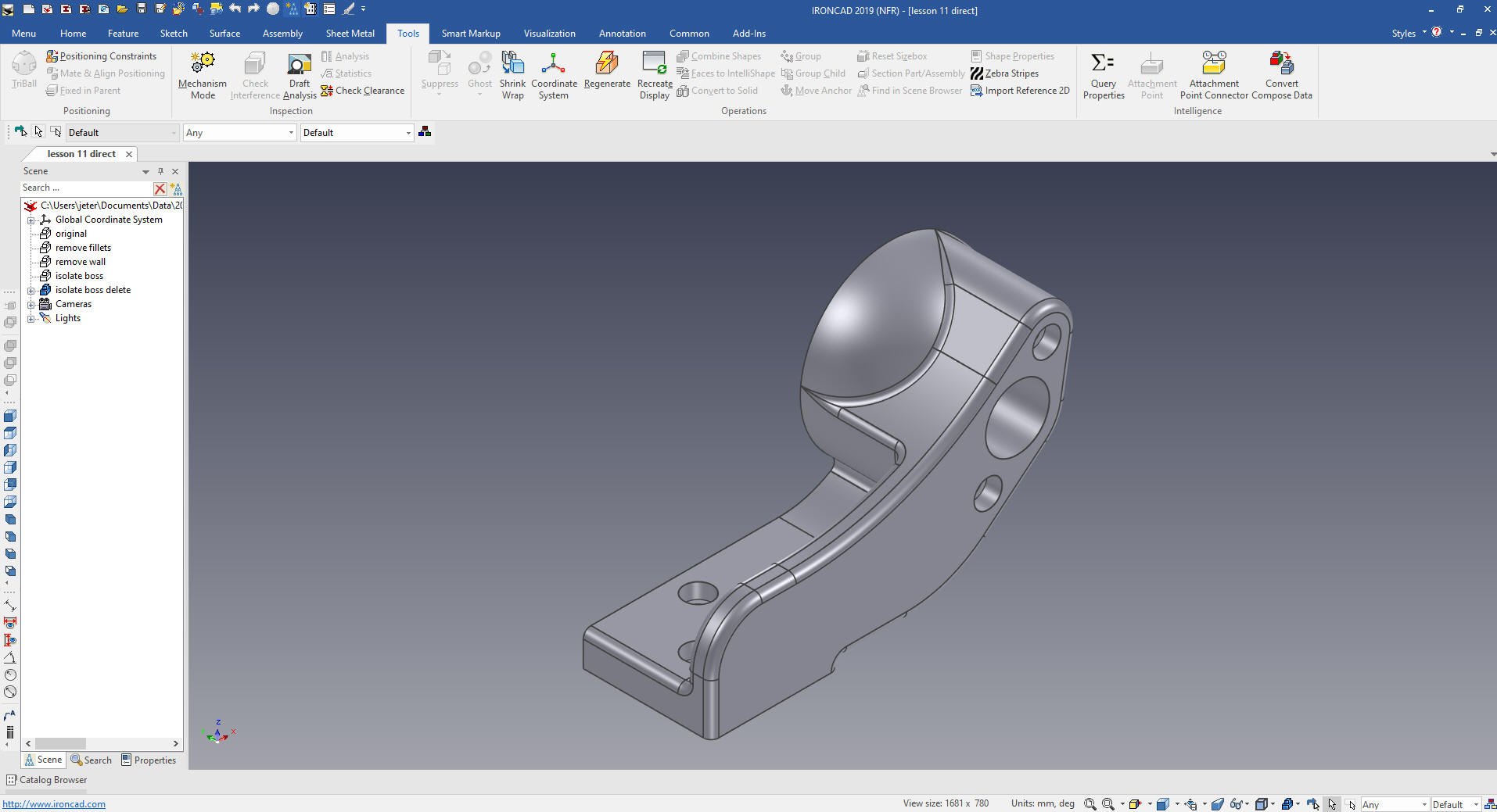
Now for the blends. Hmm just a little bit of final tweeking and
everything is finished
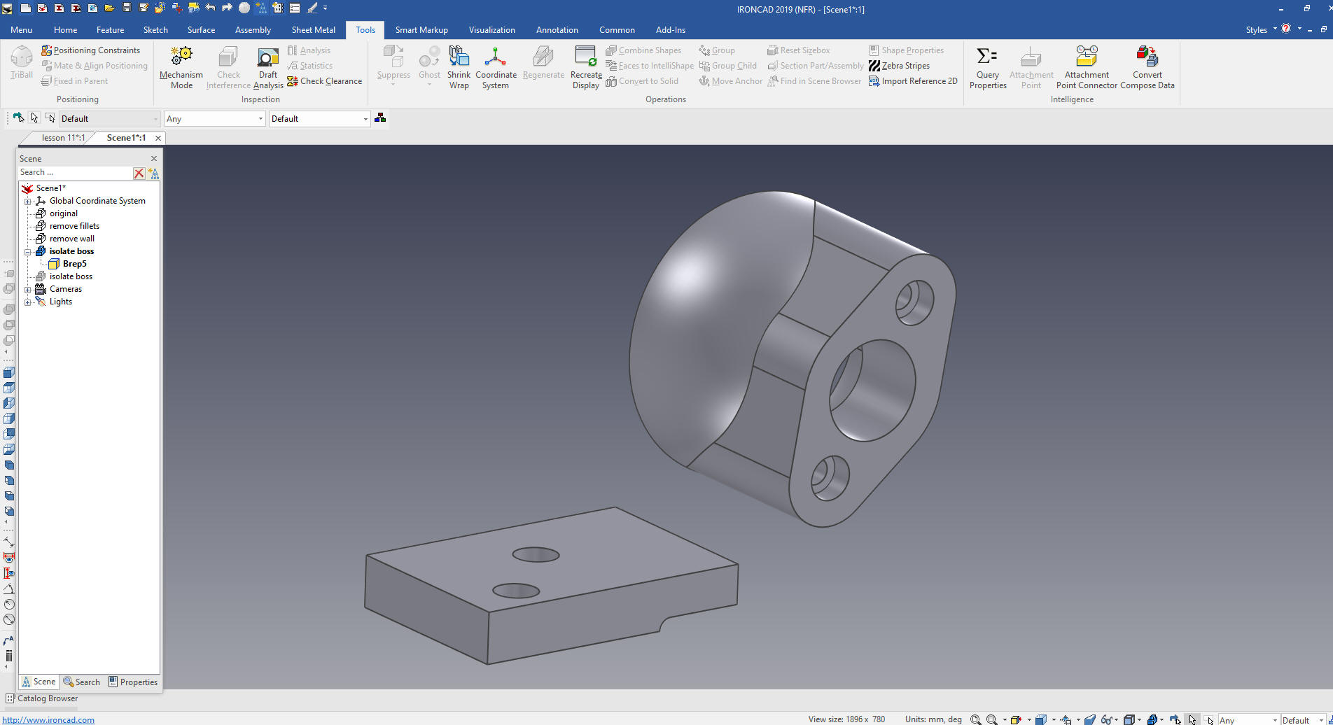
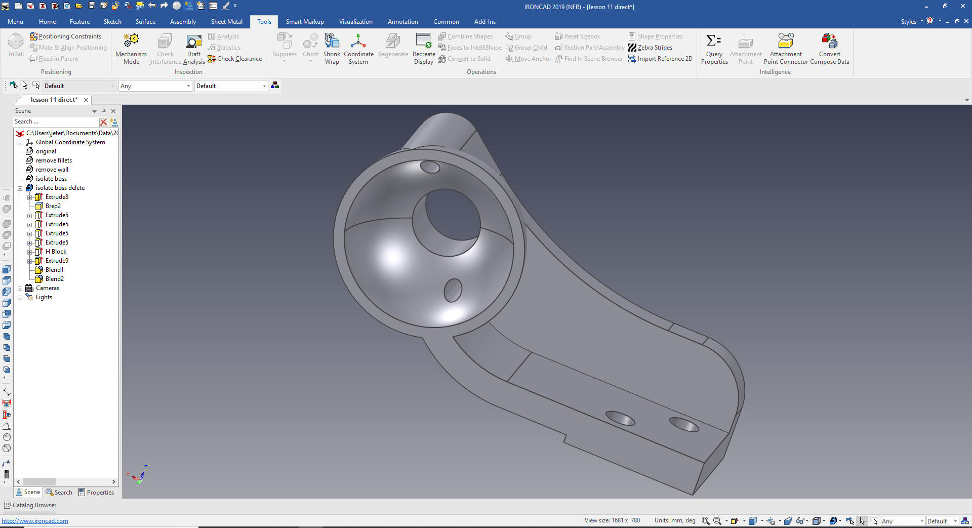
You can see both the modeled part and the direct edit of a dumb
model are identical
Now we are ready for the AIDs (drawings)
We have two files for the two parts and AIDs.
Here is -1
MOUNT detailed
When
we create sheet 2 and set it to configuration -2 MOUNT
This is
another stark examples
of how Streamlined Sketching and Feature Based Modeling utilizing IronCAD's drag and drop of smart editable
intellishapes from a catalog and
the use of the Triball can increase productivity easily 5X. I
usually estimate 5X increased productivity in conceptual design and
10X in changes, and I believe I am being conservative. IronCAD can
edit most of the Solidworks clone parts and assemblies faster than it
can be done in the native CAD system.
Give me a call if you have any
questions. I can set up a skype or go to meeting to show this part
or answer any of your questions on the operation of IronCAD. It
truly is the very best conceptual 3D CAD system.
If you are interested in adding professional
hybrid modeling capabilities or looking for a new solution to
increase your productivity, take some time to download a fully
functional 30 day evaluation and play with these packages. Feel free
to give me a call if you have any questions or would like an on-line
presentation.