3D Modeling Techniques IRONCAD vs Solidworks
Lesson Seventeen Of Course It's an Assembly No
Sketching/Drag and Drop Design
When I introduce IronCAD's very
flexible design paradigm I have a hard time to get the Pro/e clone
users, like Solidworks and other programs, to understand the drag and
drop design paradigm. With these lessons I introduce you to a new
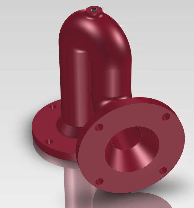
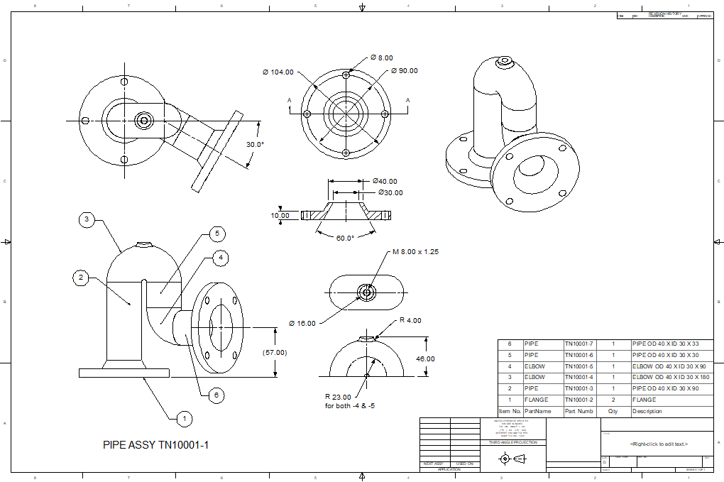
world of Mechanical CAD! This model should be an inseparable assembly. When
you are teaching someone 3D CAD the models should represent real
design. In this case we should be using standard piping fittings.
Teaching 3D Mechanical CAD offers two levels of training: Modeling
and Form, Fit and Function design. Both should be considered when
providing lessons.
IronCAD is a SME so top down design is a
normal part of our design process. Doing assemblies in Solidworks and
other clones offers different
challenges with creating each part separately. This causes an extra level of
documentation that is already causing chaos in the industry.
The sweep command would be more appropriately
applied for
tube design.
Please watch
as the Solidworks presenter models this part! Even with separate parts, we do
it faster.
While creating 3D models from drawings is the very best
way to learn 3D CAD and maybe some design techniques it does not
expose the designer to the design flexibility necessary in design. IronCAD is all top down due to the single model environment.
Creating mating parts is a cruise. But modeling is just one aspect of a
well designed productive 3D CAD system.
IronCAD vs Solidworks
I would do a
video, but I really am not good at it. So I will show you step by
step. I will try and get IronCAD support to create one. They are
very good. We are going to create an assembly. No
preparation required, IronCAD is a true SME (Single Model
Environment). Watch as I create each part in the same scene. IronCAD
offers a much easier and simpler design process.
Here is IronCAD. My default is inches,
so we will set the units to mm. Let's get started.
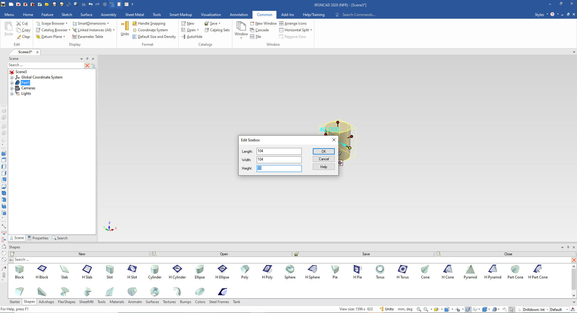
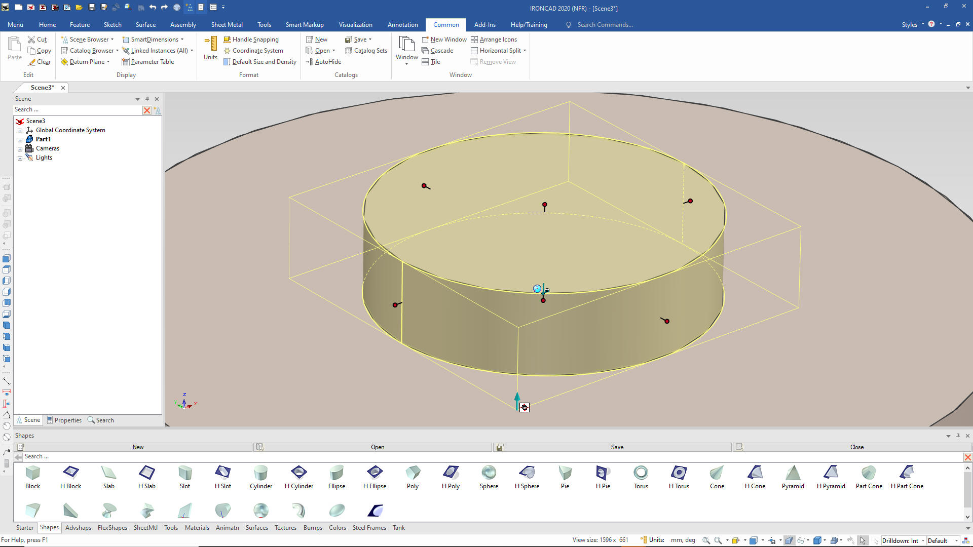
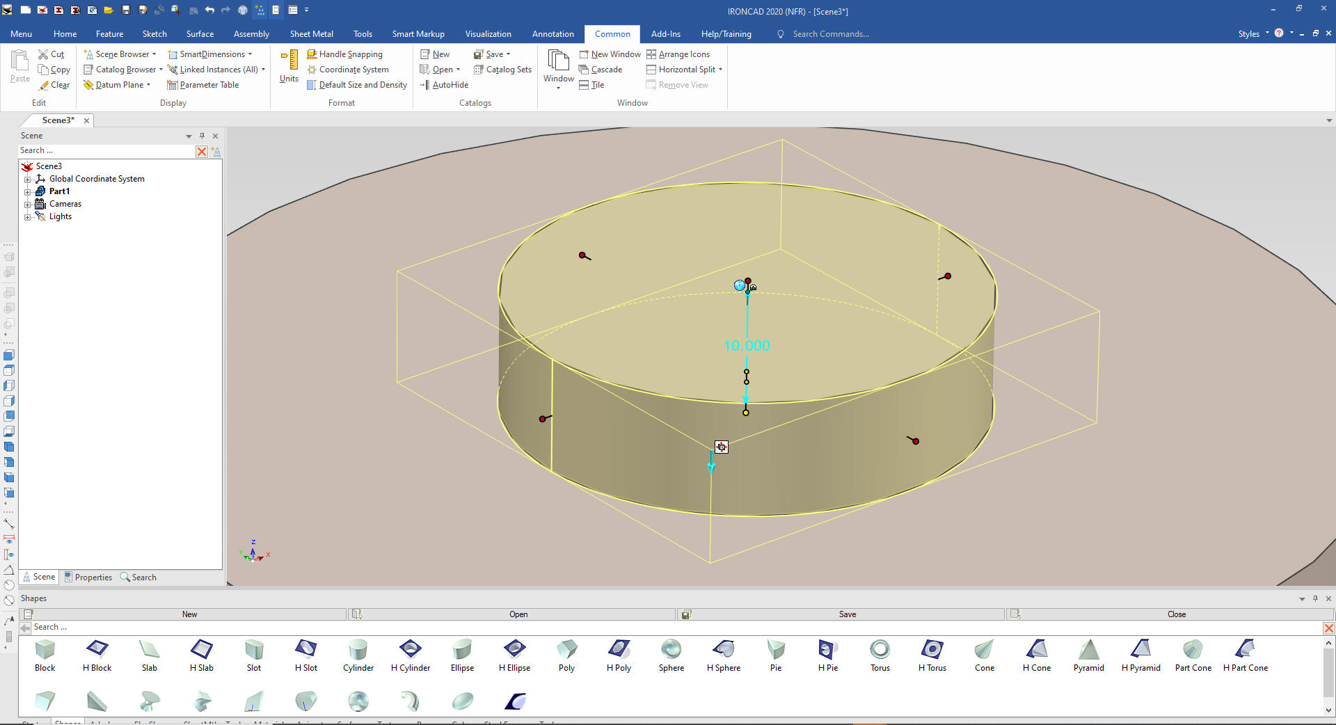
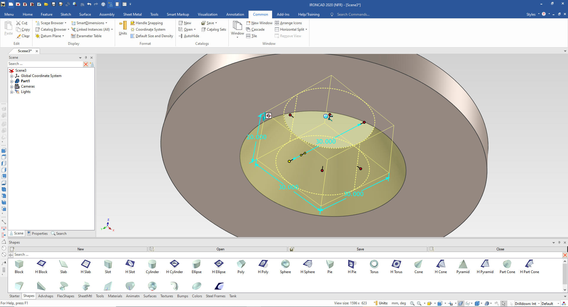
We will start with flange by dragging
and dropping a cylinder into the scene and size it. IronCAD drop the
first shape at X0YOZO.
Note: Why does IronCAD call it a scene instead of a workspace?
IronCAD was first released as a graphic design program called
Trispectives. It still has much of the graphic design functionality.
It truly is a wonderful mixture of professional 3D CAD and graphic
design, which puts it in a much more flexible category as compared
to the Solidworks clones.
We
now drag and drop another cylinder to the center of the top face of
the existing cylinder and size it.
Do you see the small arrow
in the lower corner? All of these "Intellishapes" are based on
sketches and in this case extrusions. I want to reverse this
direction so do to a modification to the shape only available in
IronCAD.
We right click on the feature. IronCAD has levels of
operation defined by colors. Assembly - yellow, part - blue, feature
- yellow (what is shown and face or surface green.
We will
select flip extrusion direction. We will pull the handles to reset
the correct location and size.
You can now
see the arrow is pointing down indicating the direction of the
extrusion.
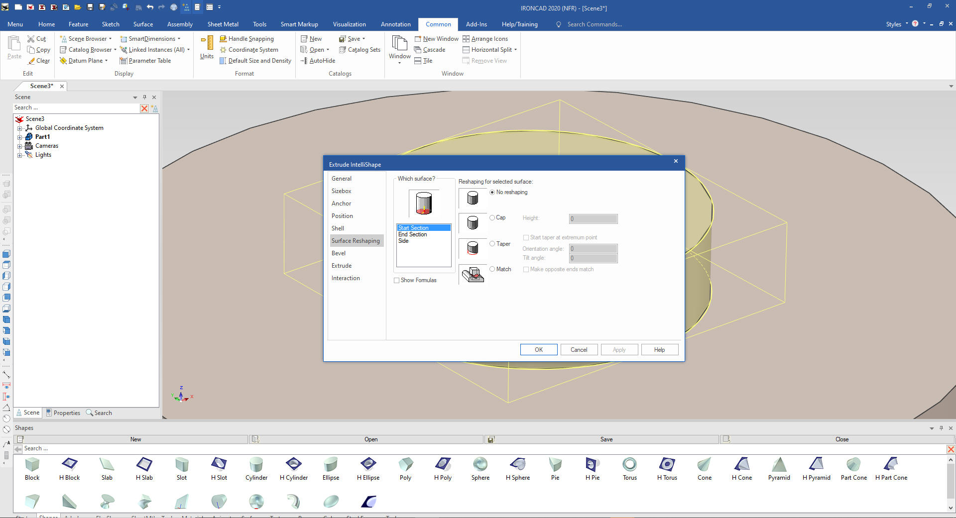
I will now show you why
they are called intellishapes! We can
now modify the feature directly with a variety of commands from
Shelling, Bevels (blends and chamfers) and surface reshaping which
we will use.
We set
the side taper to 30 degrees and we are done with this feature.
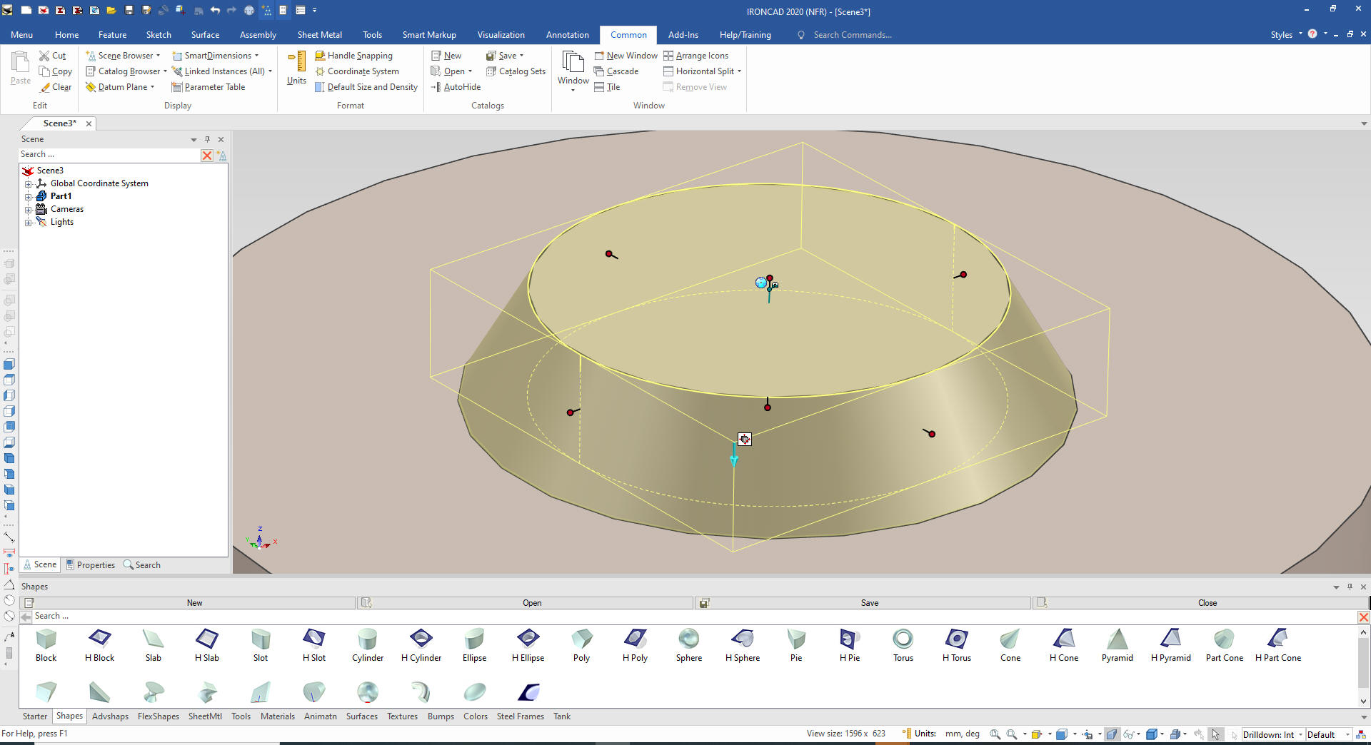
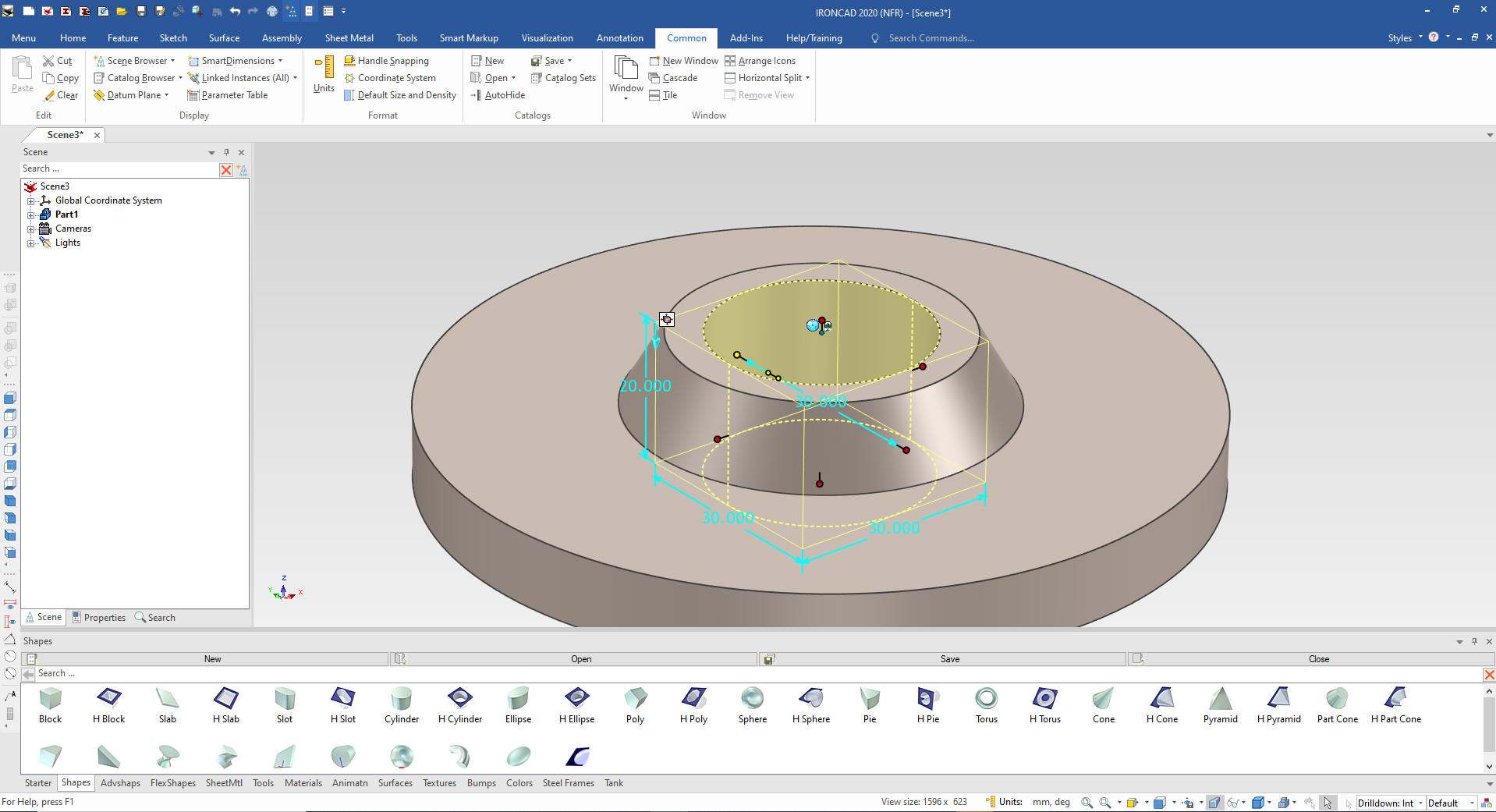
Now for the
hole. We drag and drop the hole cylinder on the center of face top
face of the flange and size it.
We again select the new hole feature
and right click and select the surface reshaping options and set the
side to taper 30 degrees.
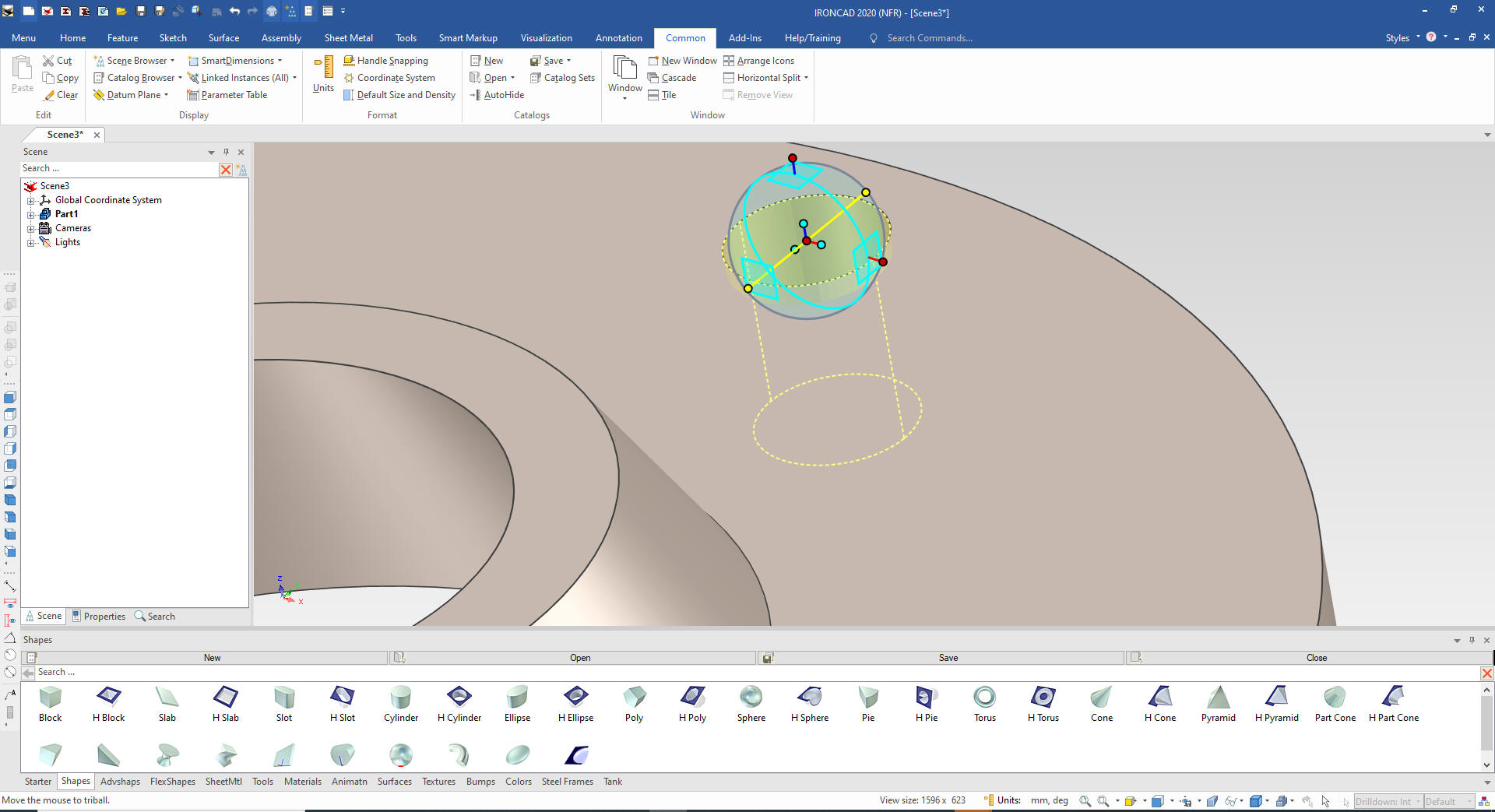
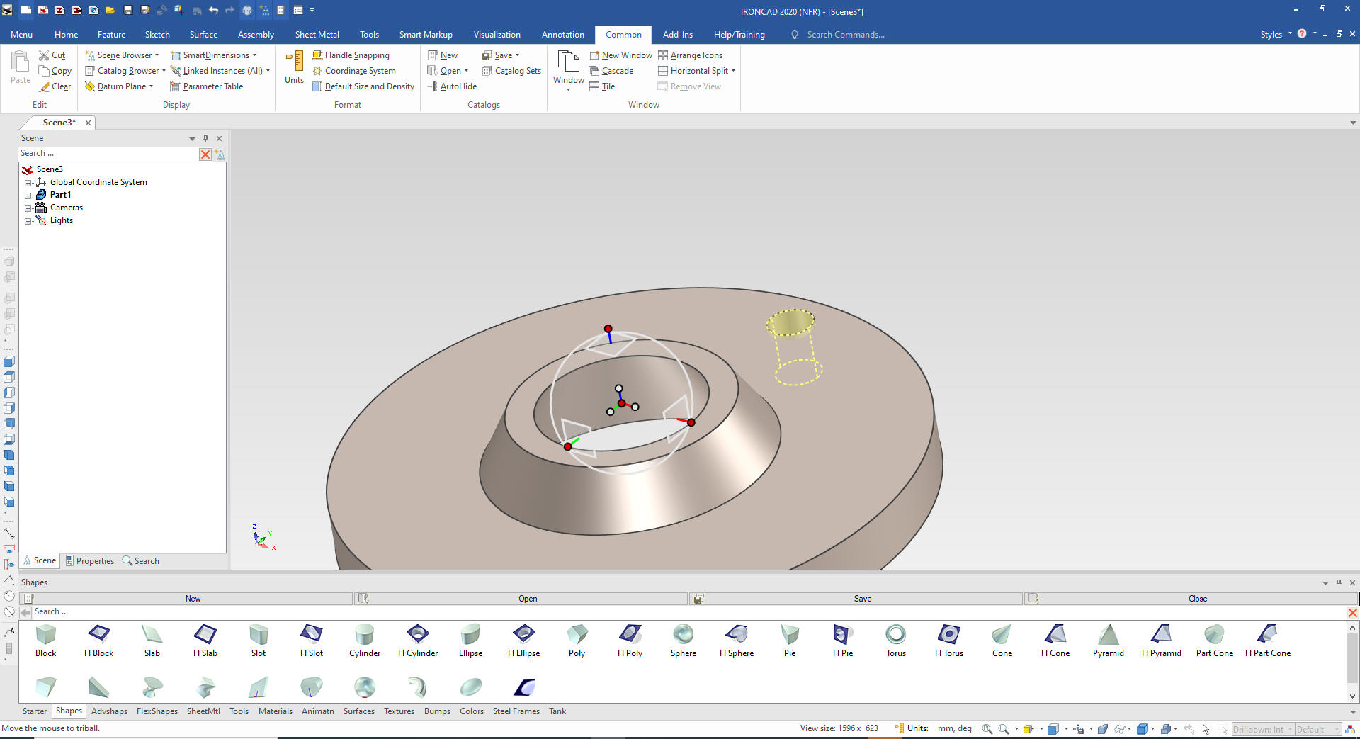
We
drag and drop a hole cylinder on the face of the lower cylinder
locate it with the Triball and size it.
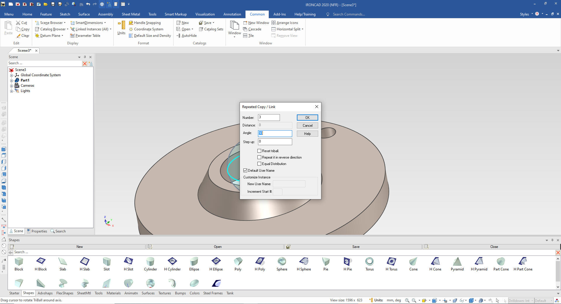
We need four holes so we move the
Triball only, by pushing the space bar and moving it to the center
of the flange.
We Turn the
Triball back on and set the rotation and how many copies we want to
link.
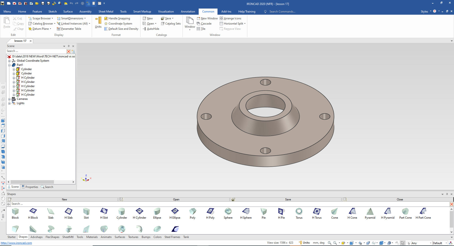
We are now done with the flange.
I
want to introduce you the the incredible standard catalogs. We have
a variety of functions far beyond the shapes. We will be using the
tank catalog for the piping! We will first drag and drop a pipe from
the catalog. They have attach points that automatically line them
up.
We will Select the feature level and edit the ID, OD and
length.
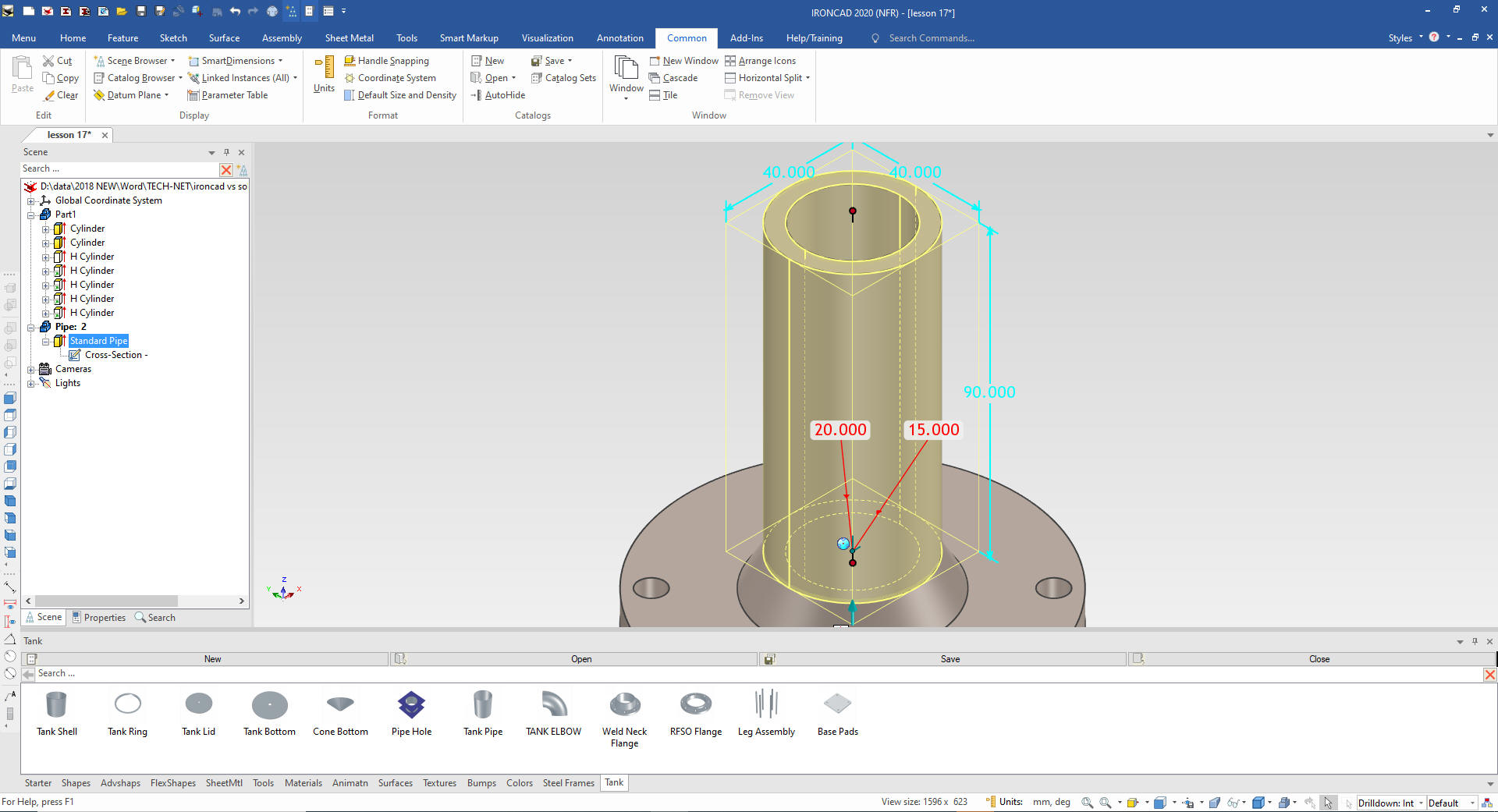
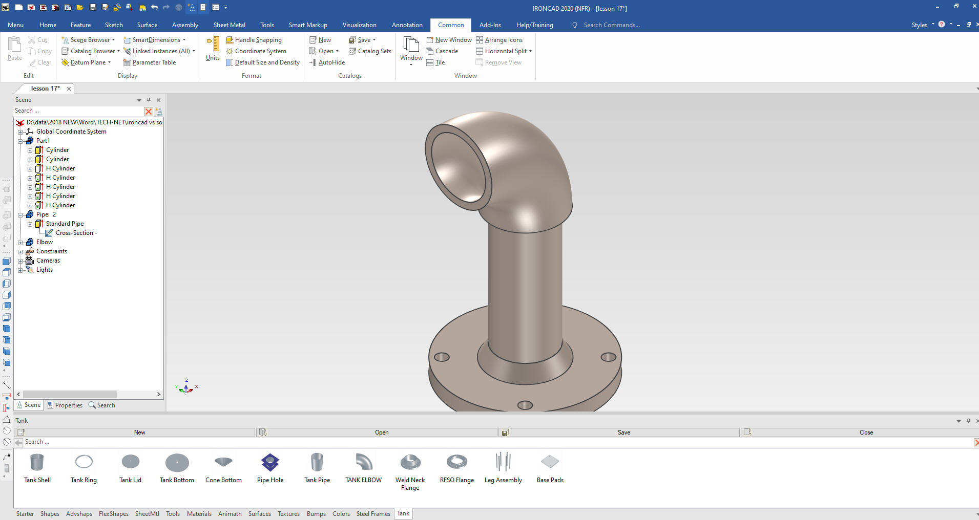
We
now drag and drop an elbow a the top of the pipe.
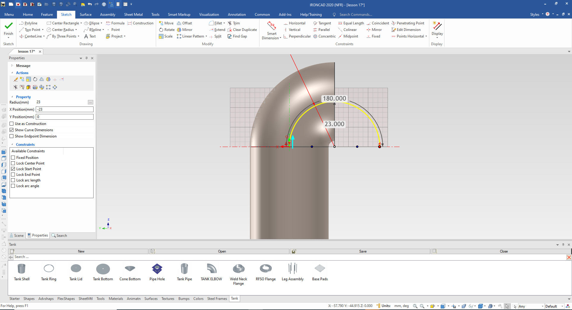
We now
redefine the shape by editing the sweep which includes the sketch of
the pipe and the sweep radius and rotate it into place with the
Tribal.
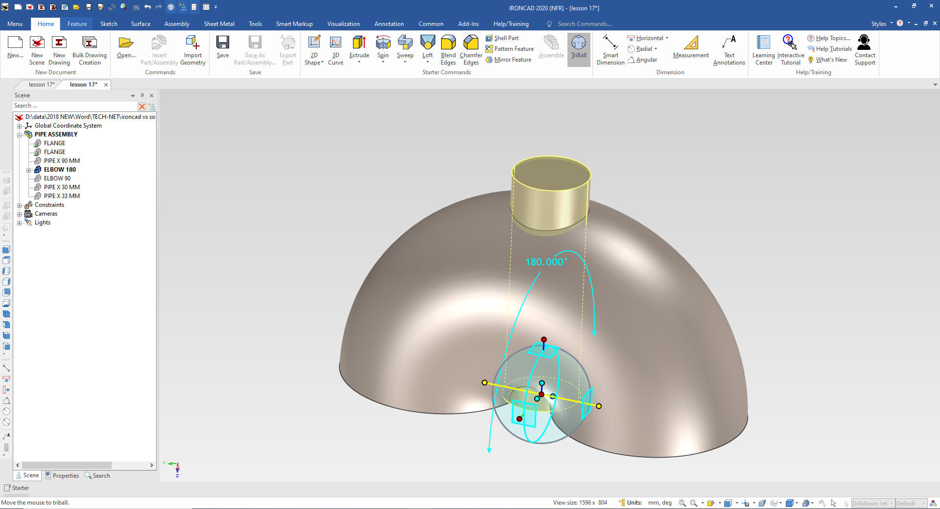
We copy and paste the modified elbow and
suppress the new elbow we will be using it later. We now edit the
sweep to be 180 and we are done with this elbow.
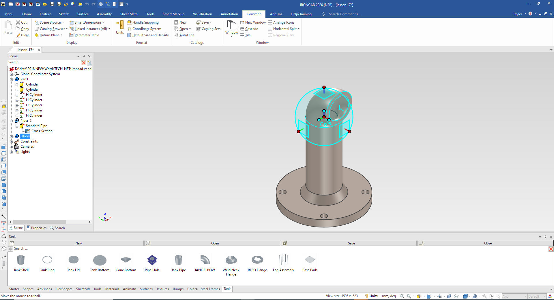
We
never create another pipe feature we just copy it using the Triball
to the new location. We set the length.
Now we take the 90 degree elbow and using the Triball we locate it
to the end of the new pipe and rotate it into place.
We
copy a another piece of pipe to the end of the elbow with the
Triball and locate it. This is called reusing features or parts.
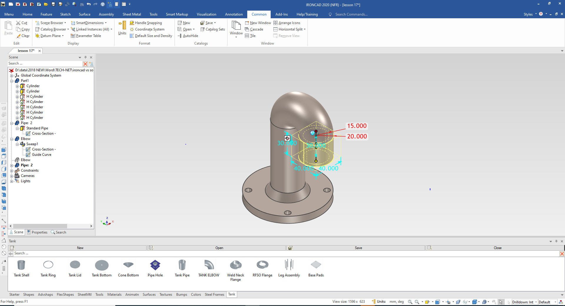
Oops
we forgot the fitting on the 180 degree elbow!
No problem we
show only the elbow and drag and drop a cylinder on the bottom face
of the elbow, located it with the Tribal and rotate it 180 degrees.
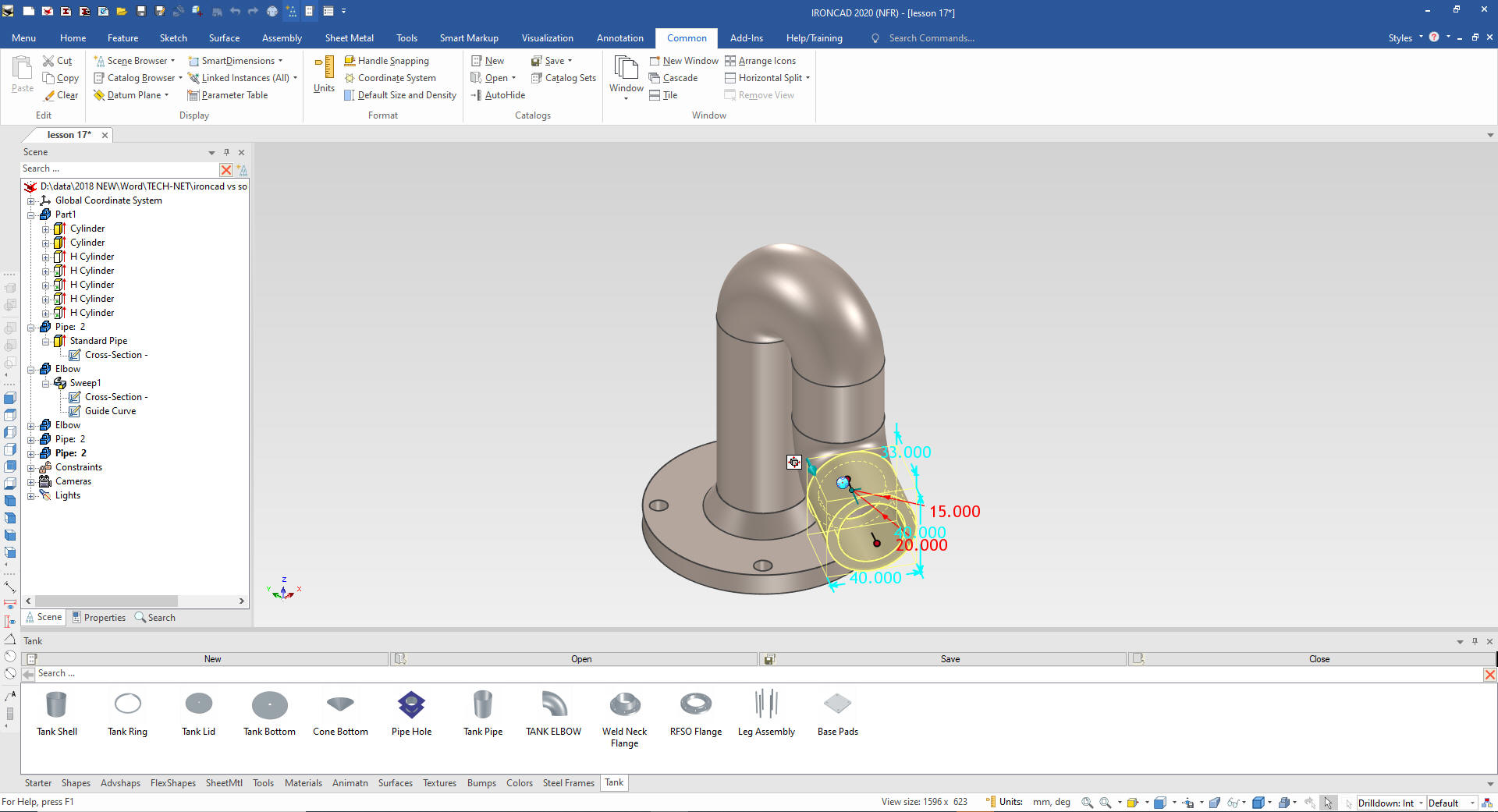
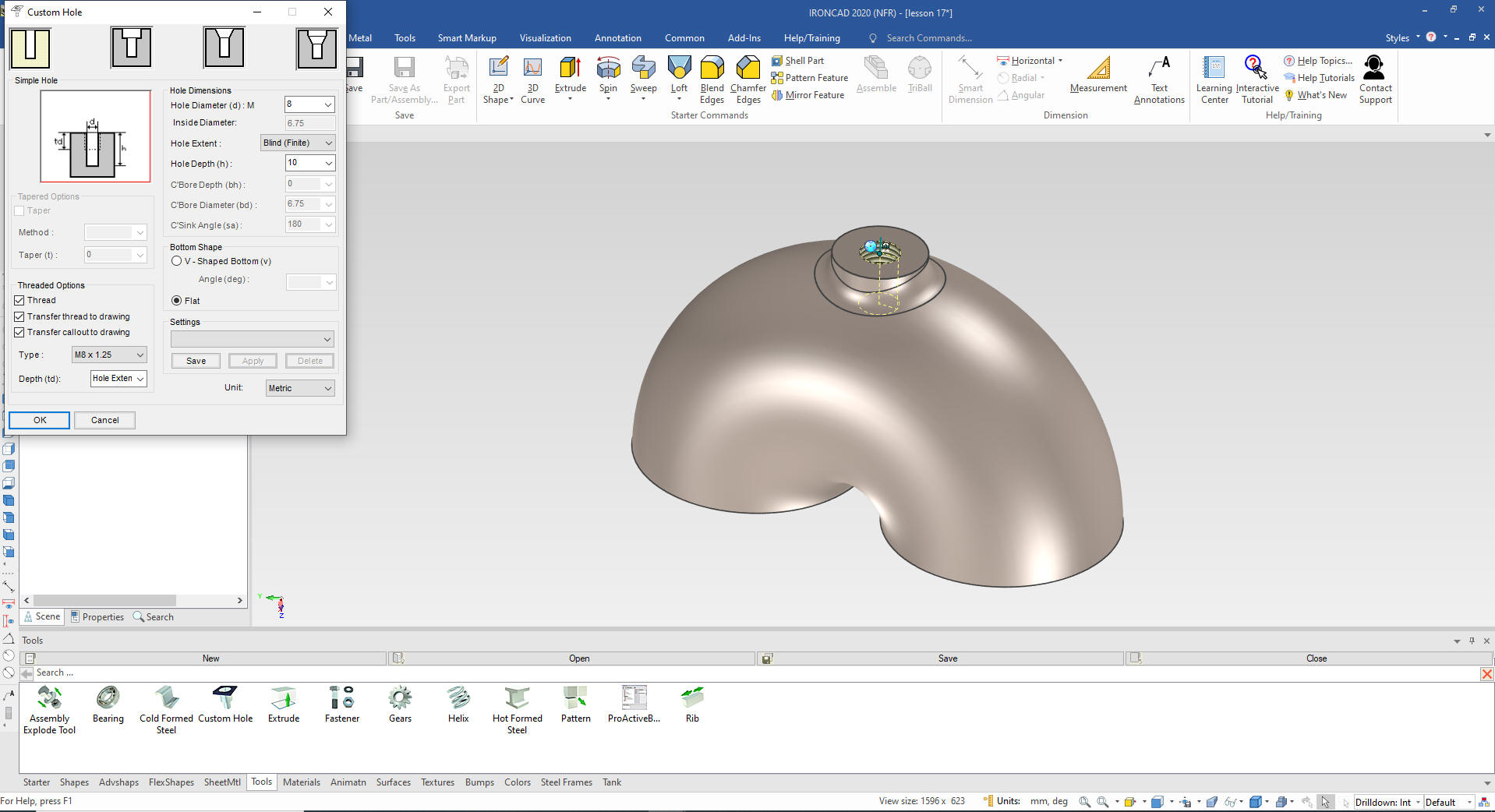
We
size it add the blend and go to the tools catalog and drag a custom
hole to the center of the boss and
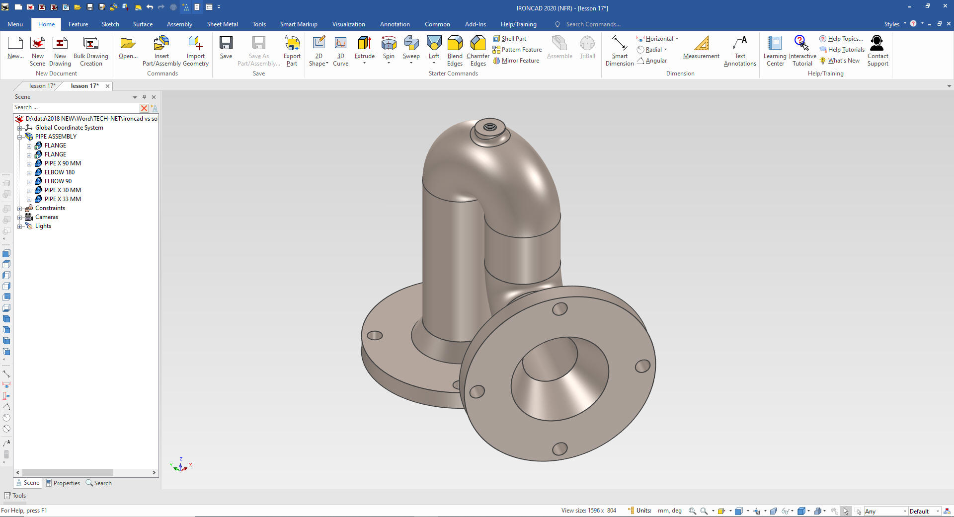
Using
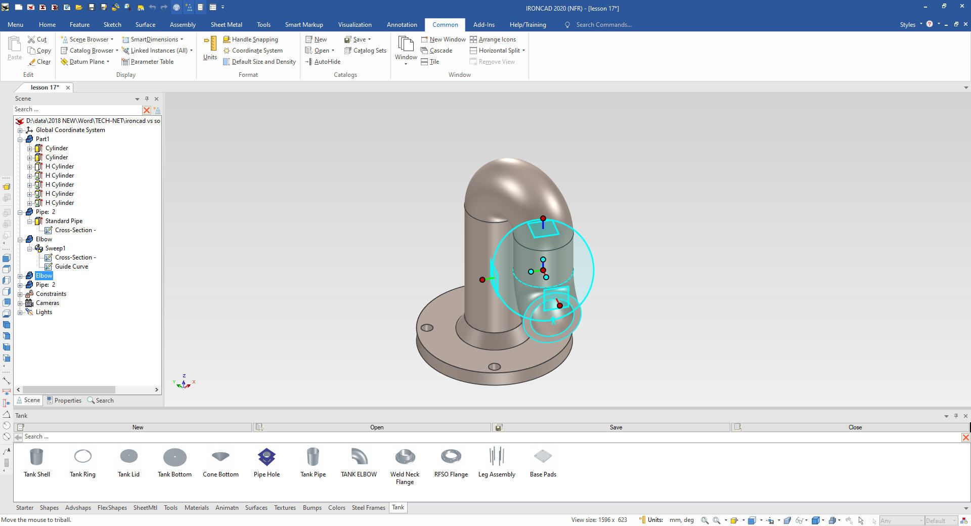
the Triball, by know you can see how important the Triball is, we
link the flange on the end of the new pipe and rotate it into place.
We will set the catalog to autohide for more scene real estate.
We are done with the assembly. No sketches and creating the assembly
like they would do it physically. IronCAD is the very best
fabrication CAD system especially inseparable assemblies like this
pipe assembly.
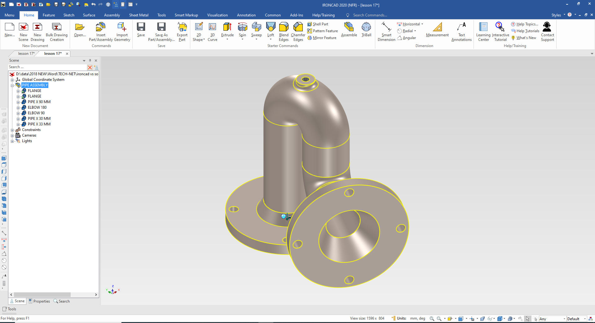
And
we are done with all of the parts. But this is an assembly so we
select all of the parts and the parts, right click and select
assemble and rename it to Pipe Assembly. You can see now our
assembly is denoted as yellow.
But what what if we didn't have the pipe and pipe fitting catalog. I
will show you how easy it is to create the pipe and elbows with drag
and drop components.
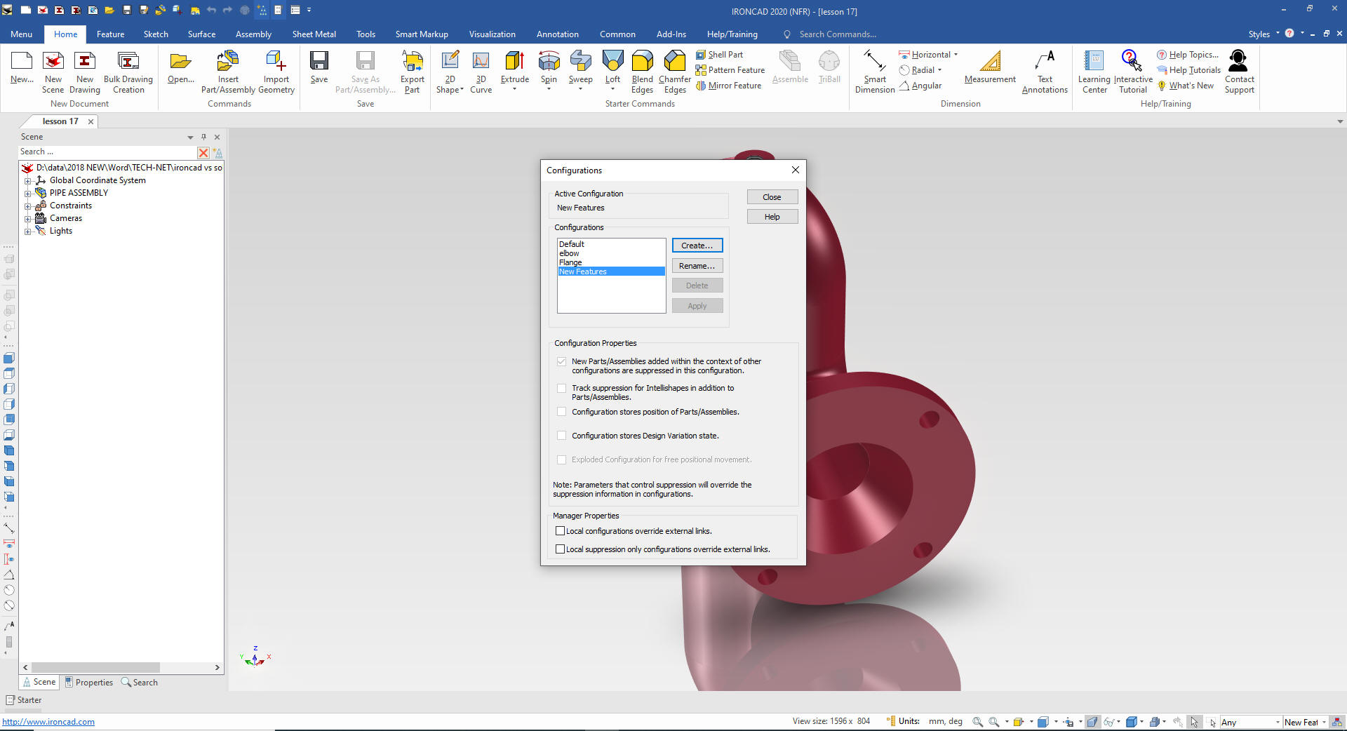
The first thing we do is create a new
configuration. This is how you manage your different parts and
assemblies. You can have many different iterations of design in the
same file. A great example of this is documented in this project
"Evolution of Design"
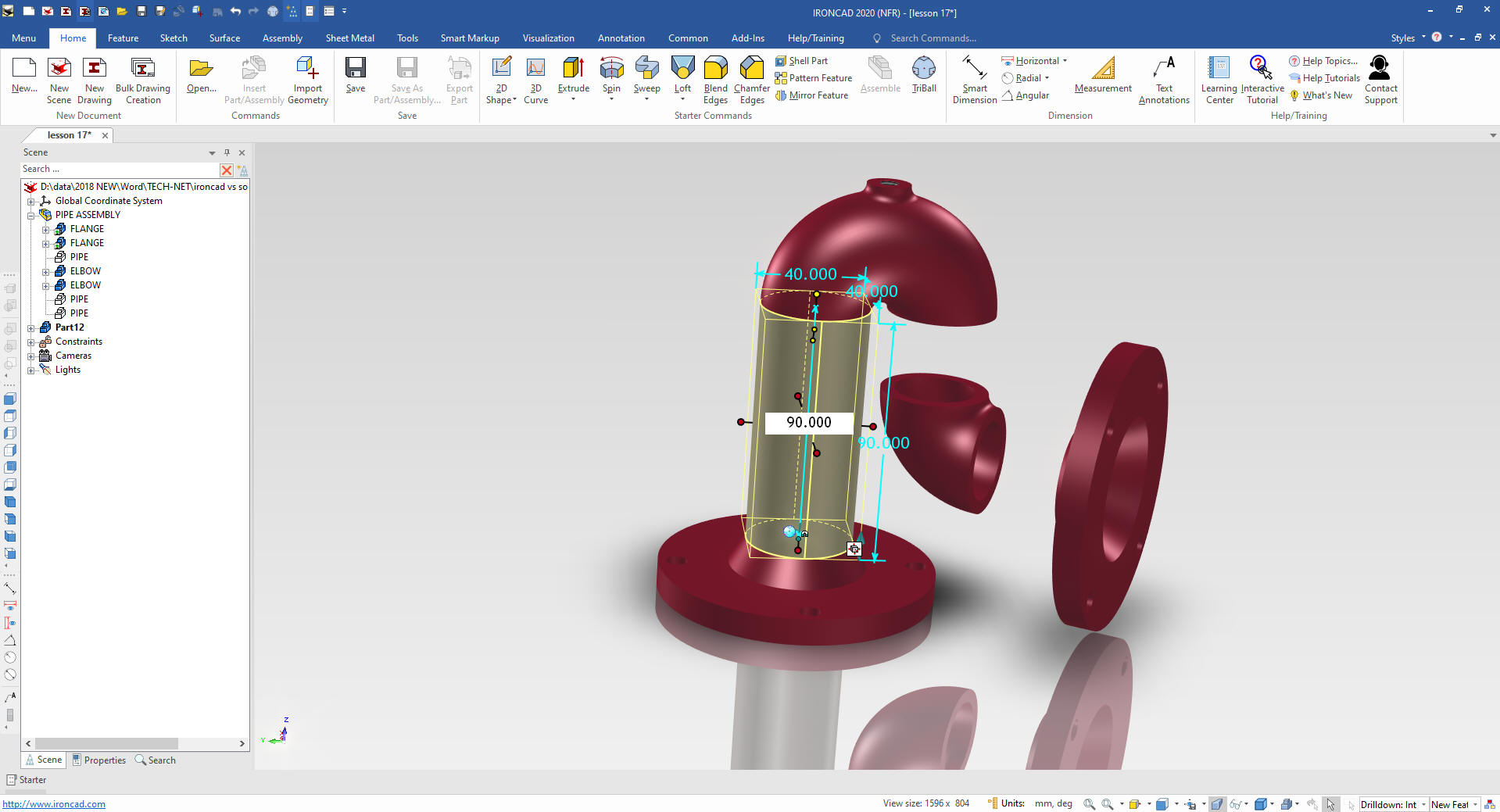
THE PIPE
Using the right mouse button we drag and drop a
cylinder on to the center of the flange and select "Drop as Part"
and size it. As you pull the length handle, you depress the shift
key which will now recognize connection points, edges, mid-points,
corners and centers.
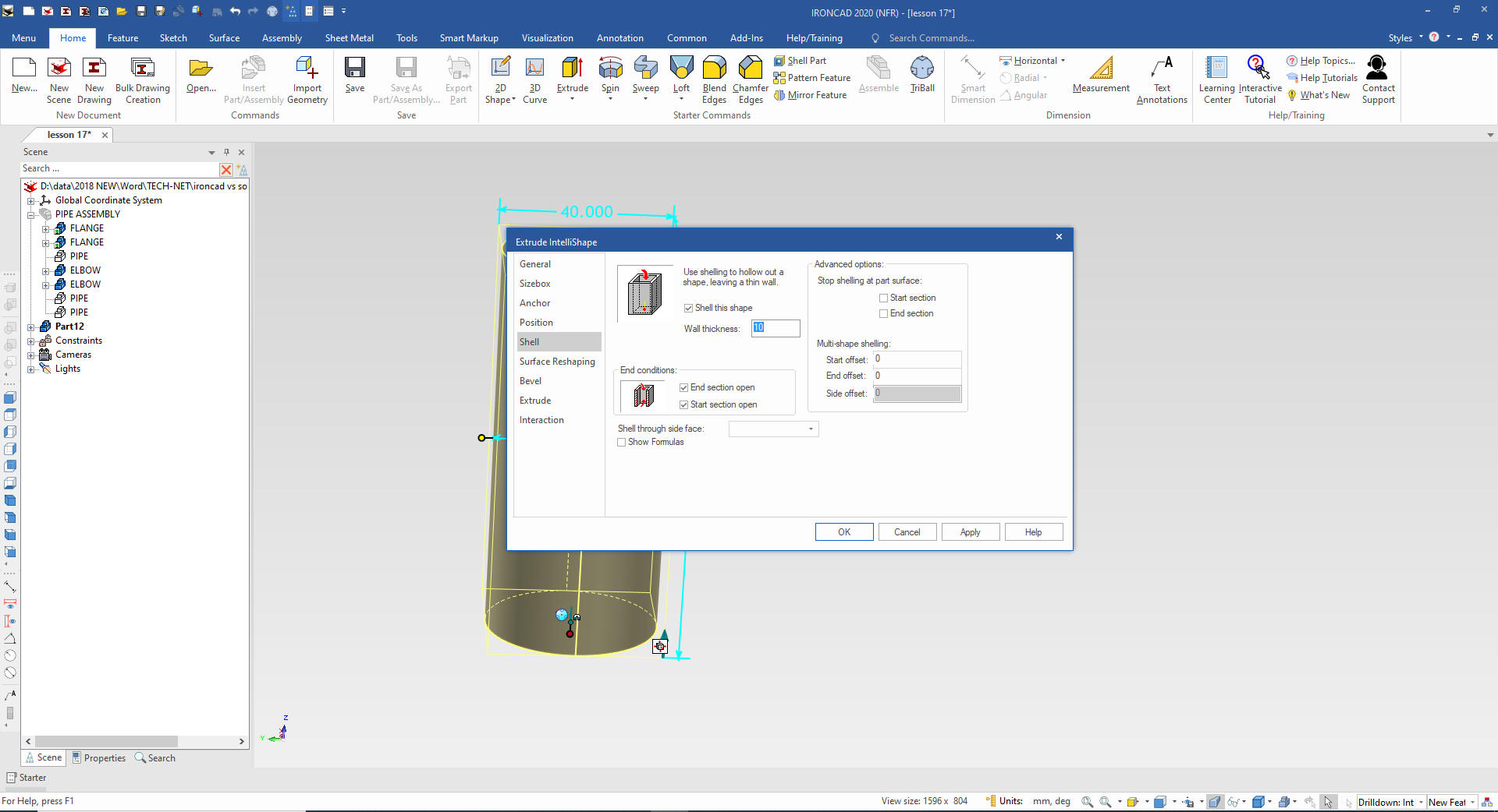
We
will hide all parts except for the new pipe. We select the new part
with the left button two times that takes us to intellishape level.
We right click and select surface reshaping and select shell.
We select end and start sections open.
Think of the added
flexibility of design with just this function as compared to the
major CAD sketched based systems.
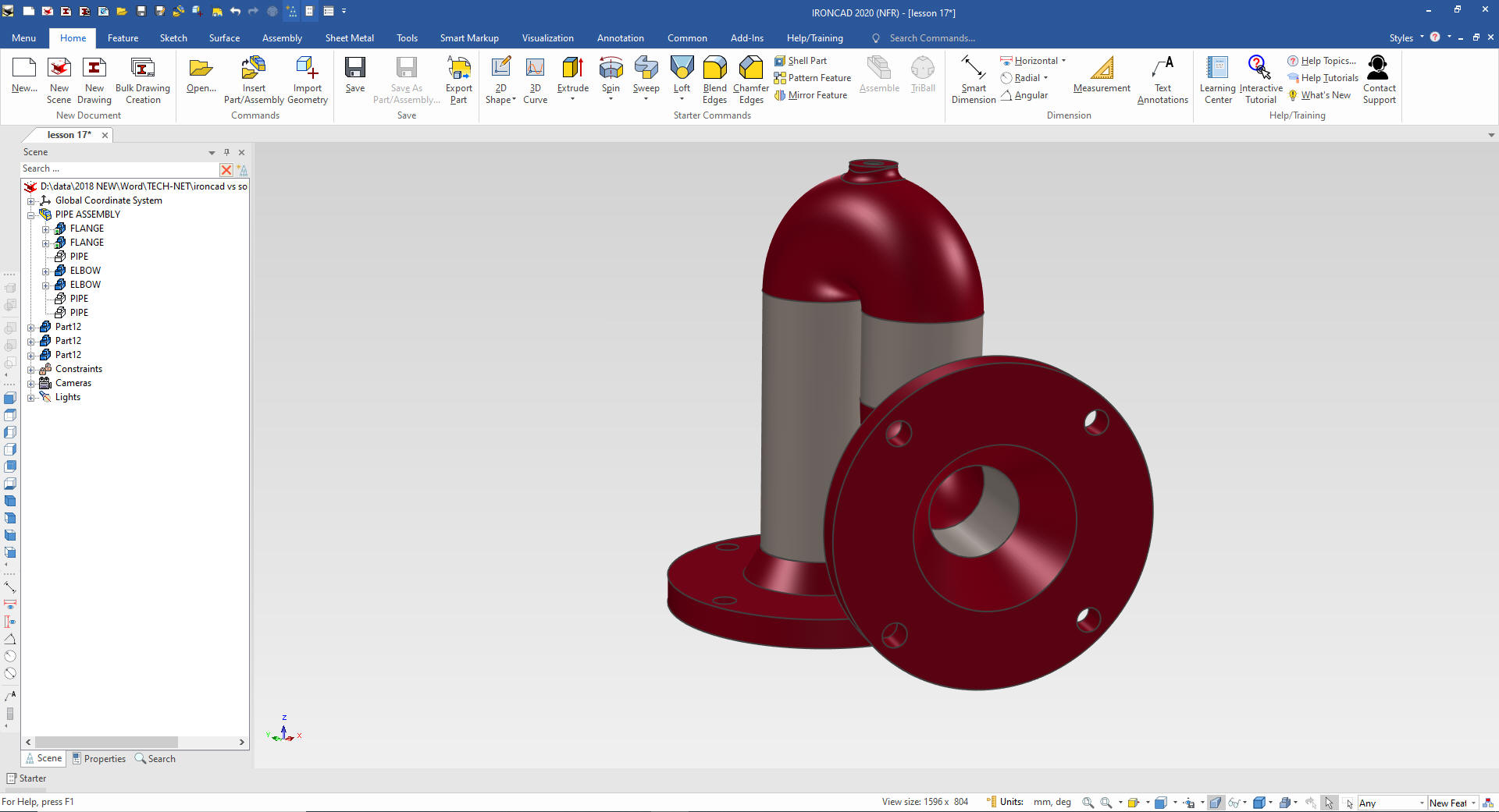
Now
we have our pipe ready to be used any where we would like.
We
select show all and by using the Triball, we copy, locate and size
length the pipe in the other locations.
Now
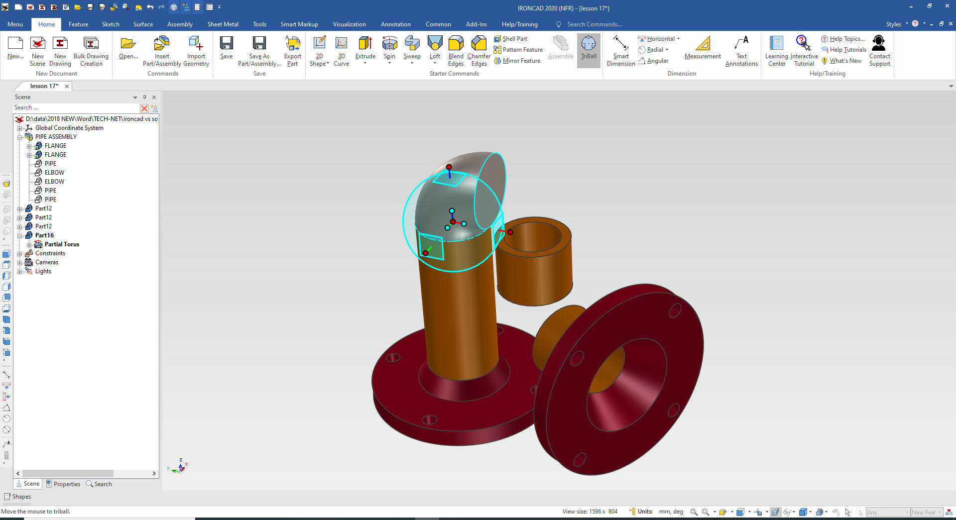
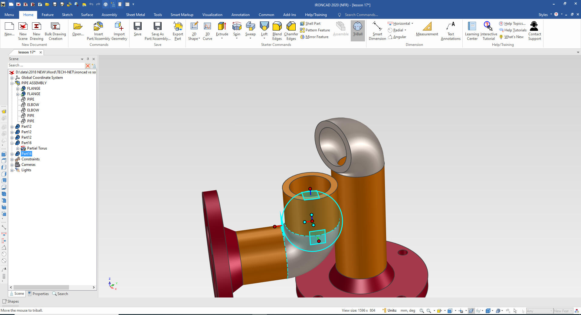
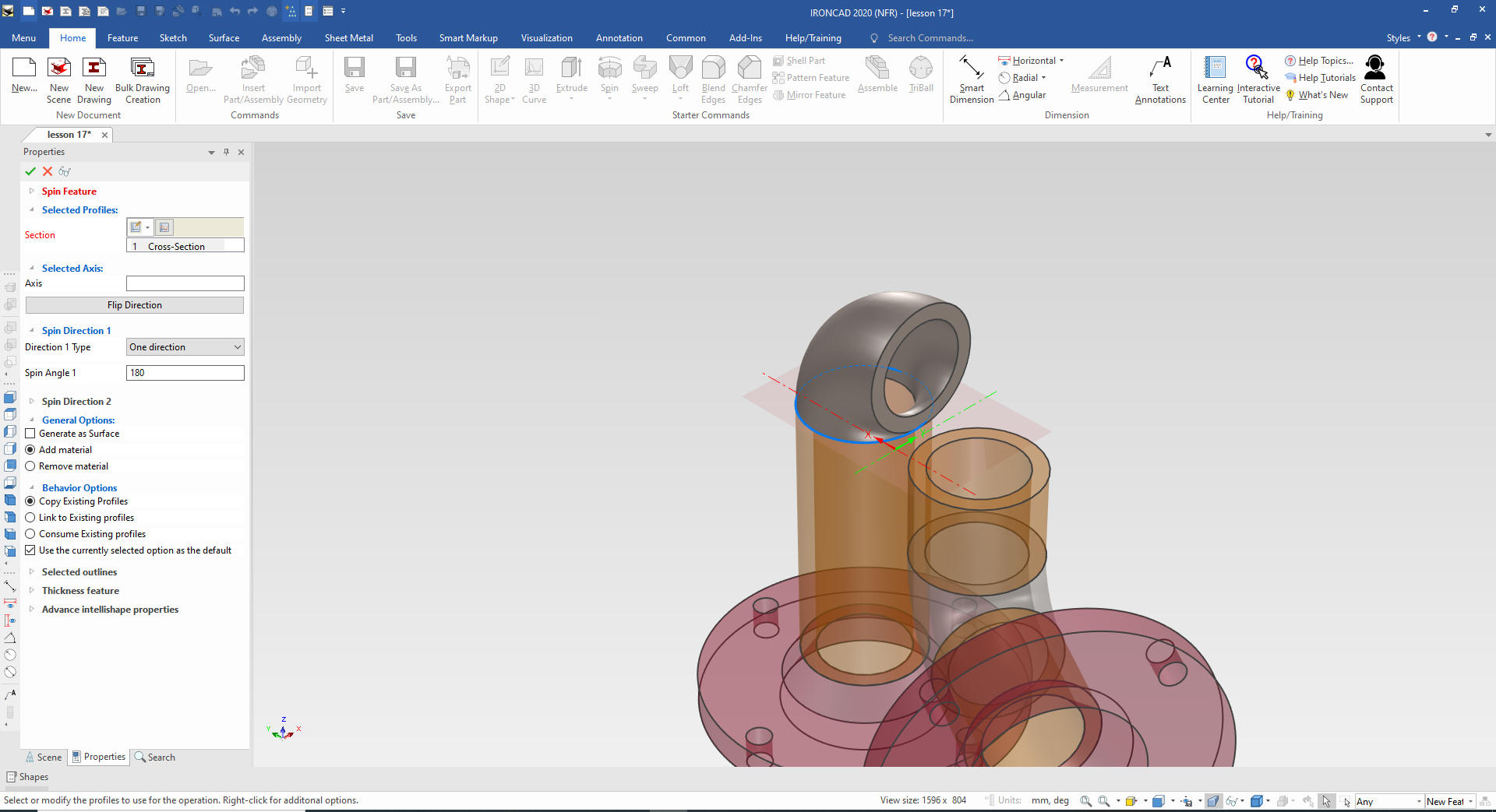
for the elbows. We drag and drop a Partial Torus into the scene size
it and locate and and rotate it.
We
edit the intellishape to shell with 5 mm walls. We will copy this
elbow and copy it to the other location.
Now
we just edit the existing the partial torus and set the rotation to
180 degrees.
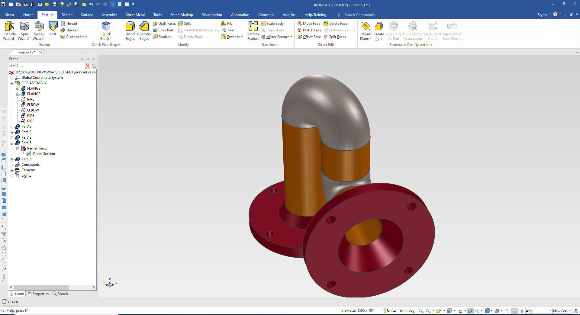
We
are done with these parts. Done a much different way only available
in IronCAD. I could also create them from sketches and extrude and
spin them. IronCAD offers so much more flexibility that increases
your productivity. Designing in a SME (Single Model Environment)
makes top down design your normal design process.
The pipe and fittings can be defined in
the parts list.
Give me a call if you have any
questions. I can set up a skype or go to meeting to show this part
or answer any of your questions on the operation of IronCAD. It
truly is the very best conceptual 3D CAD system.
If you are interested in adding professional
hybrid modeling capabilities or looking for a new solution to
increase your productivity, take some time to download a fully
functional 30 day evaluation and play with these packages. Feel free
to give me a call if you have any questions or would like an on-line
presentation.