ZW3D vs Fusion 360 Lesson 16 3D Modeling Techniques Defined
Alternate Sheet Metal Modeling Streamlined Sketching/Feature Based Modeling
The modeling technique is
hugely responsible for the level of productivity. Those of you that
are only trained in the sketch, sketch, constrain, constrain world
are truly limited by not using the freedom of Streamlined Sketching
and Feature Based Design,
that is available in even the most Pro/e-ish of CAD systems. If your
designers are designing in these very unproductive and time
consuming processes it might be time to review your standard design
processes. Don't have any do you? I am not
sure if it is due to these exercises but I have replaced a few Fusion 360
with ZW3D. Listen to what these two fellows said. Brian
"We spoke a year and a half or so ago about
ZW3D. I took the Autodesk Fusion 360 but am becoming increasingly unhappy
with it… It’s not very productive for me, just too slow and cumbersome to
get things done quickly. On on the strength of your recommendations I am
ready to give ZW3D Standard a shot, probably as a rental for the first year.
Bottom line is, Fusion 360 is “free” but not really free… I am finding
that the slow, clumsy pace of design with it is counterproductive… time is
money."
Thanks much,
Brian
Peter
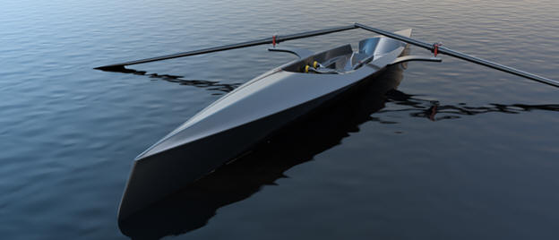
The initial hull design was done in Rhino, which for some reason
is a standard in the boat industry.
The surface already had
a few problems!
It was imported into Fusion 360 and I did
some of the early concept design work, but when it came to surfacing
I hit road blocks every way I tried it.
At this time Phil
was not part of the project, but I suggested to my client that we
needed Phil's help. Phil also hit road blocks in Fusion 360 even
using some of his unique re-topologizing workflows and T-Splines.
The rest is history, as they say.
Thanks to ZW3D
paired with Phil’s surfacing skills we now have tooling for the hull
created.
You should see the images.
Perfectly smooth
reflections!
Peter I saw the following video challenges on LinkedIn and
thought I would give them a try on IronCAD. I got a great response and
decided to do it in ZW3D. I was very familiar with the parts and did it a
bit easier. It shows more the difference in the level of the 3D CAD
experience than the CAD system itself. You can
Download ZW3D and give
it a try.
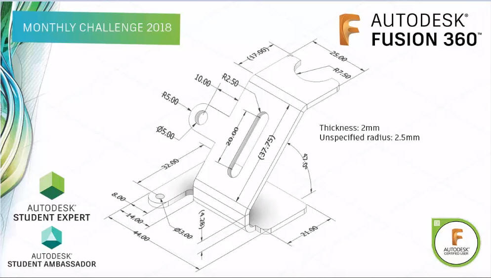
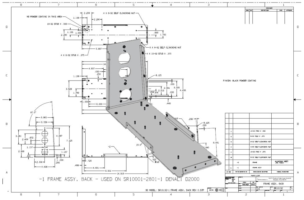
Look at the this drawing. Who details like this? It is obviously
dimensioned only to be able to easily create a sheet metal model with
the sheet metal tools. No where in the world would they detail a
drawing like this. How do you inspect it? We are going to get it
back to reality.
Alternative Sheet Metal Design
I was introduced to
3D CAD in 1982 with Computervision CADDS 4, Found PC base 3D CADKEY
at Boeing in 1986, Started using and selling it in 1987. This was 3D
wireframe, no fancy sheet metal modules. We even had unfolding
programs for the wire frame design.
Here is an image of a
wireframe sheet metal part. With CADDS 4 we started with one color!
Green on Black! They added Color for $35,000 per seat with CADDS 4X.
I sold PC Based 3D CADKEY in 1987 with full color with 90% of the
functionality of CADDS 4 and Catia 2 for $9000.00 with CADKEY, a 386
computer and 19in CRT. CADDS 4 and Catia were well over $100,000.00
per seat.
Are you looking up or down? This used to drive the engineers
crazy. Yes, in those days 3D CAD was only in the realm of draftsmen!
Enter solid modeling in
1995. We started modeling our sheet metal like we do all of our
models. I am afraid the many of the new millennial engineers really don't
know you can probably do your sheet metal design faster and easier than
with the sheet metal modules. Now, I suppose if I only designed
sheet metal parts it might be advantageous. But most of us design
projects where a variety of mechanical design is used. Machining,
sheet metal and other fabrication. So you may design just a few
sheet metal parts.
Being a Boeing trained draftsman, I have
extensive sheet metal design experience. We would do flat
pattern development on undimensioned drawings to .005 tolerance.
They would photograph them on to the tool.
Today, I
just use the basic solid modeling tools. In IronCAD I may grab a feature from the sheet metal
module, but that is it.
Here is a website that gives the
basics of sheet metal design!
ZW3D is very similar to Fusion 360 and the
Pro/e clones with differences that make it much more streamlined. It
is very easy for those users to get up and running with ZW3D. The
unique benefits over the other systems is the multi-object
environment, for easy top down design and the the integrated
drawing. You can do complete projects (parts, assemblies and
drawings) in one file. Imagine how much this would simplify PDM?
I would do a
video, but I really am not good at it. So I will show you step by
step. I will try and get ZW3D support to create one. They are
very good.
These have actually turned
these into exercises in
modeling techniques as compared to showing a more productive CAD
systems. Again, I say there are many different ways to model a part.
I see with my exposure to direct edit modelers like CADKEY, I
rarely sketch like you see the Fusion 360 fellow doing. I have always
created my basic sketches by mostly creating offsets and extending
and trimming. It seems to be much easier. I never put in a fillet that
can be created later. What do you think? Of course, this take a good
understanding of descriptive geometry.
Creating this model without
using a sheet metal module would be a snap if someone understood you
just don't dimension parts for the sheet metal module. So lets get
started.
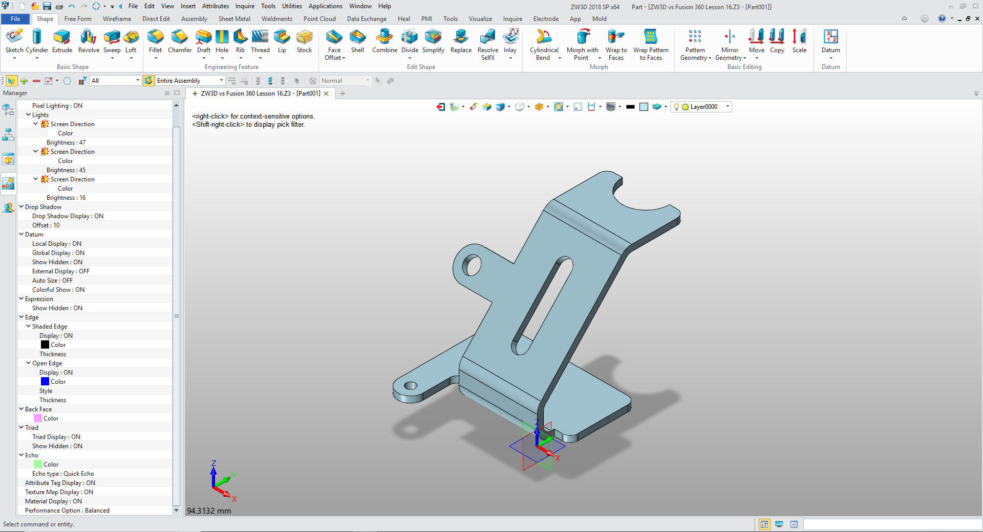
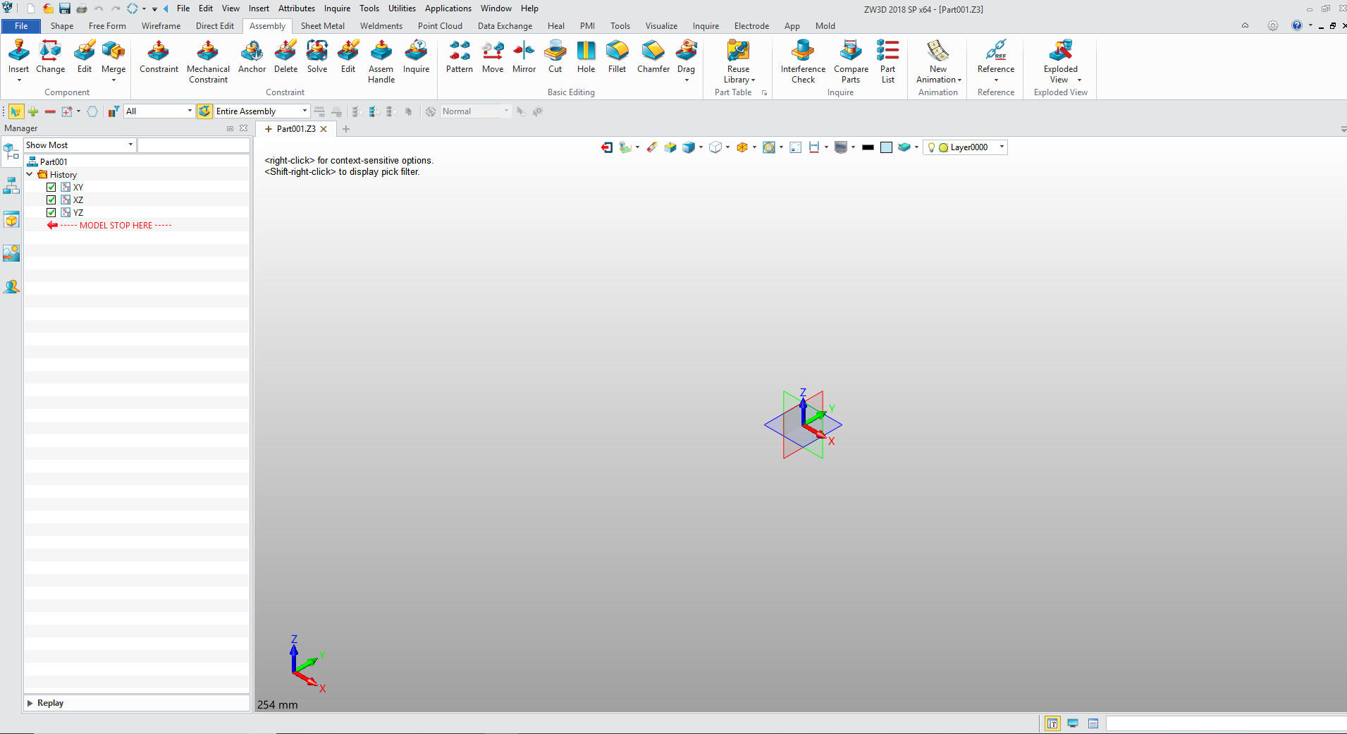
Here is ZW3D. My default is inches,
so we will set the units to mm. Let's get started.
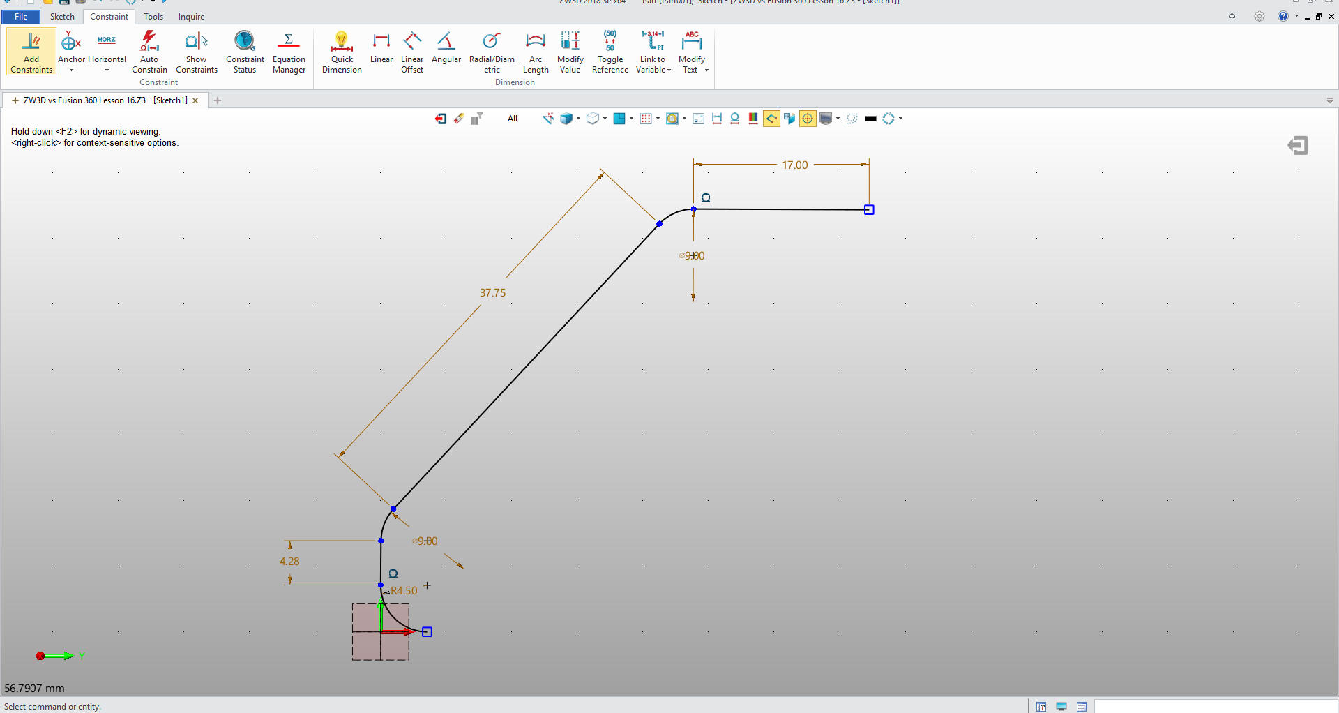
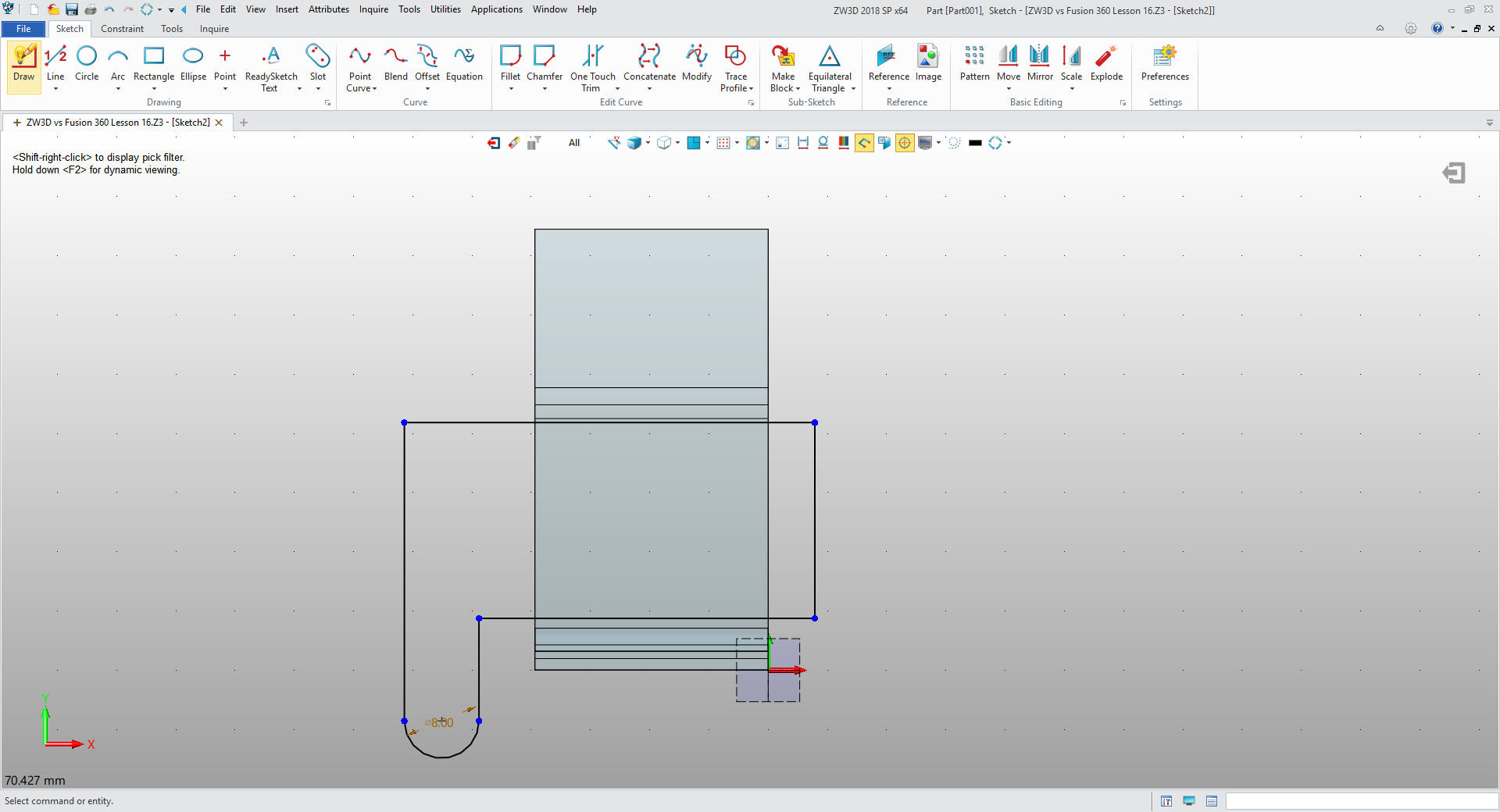
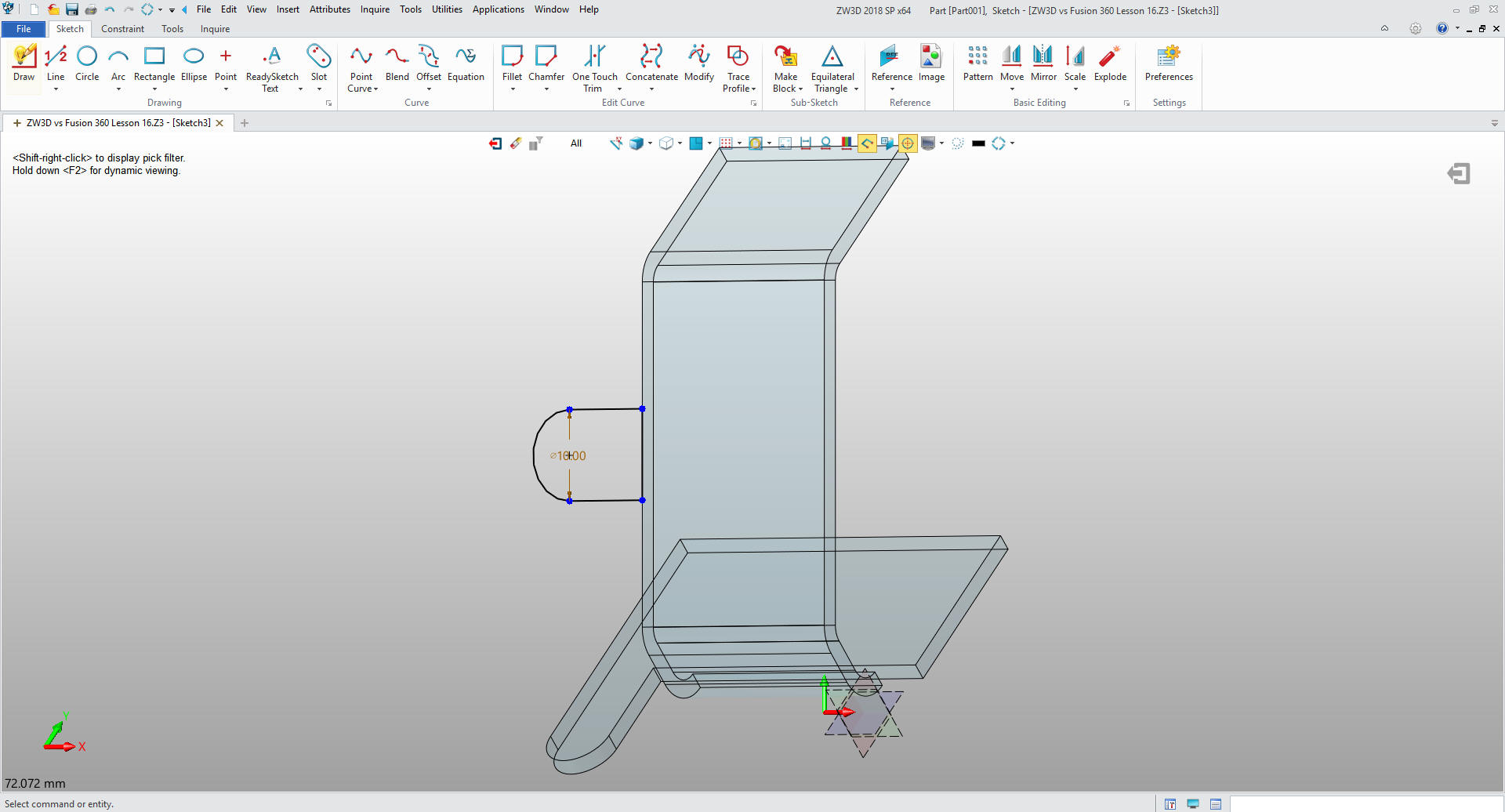
I
will just sketch the bent feature. Showing the geometry necessary to
develop the cross section from the drawing.
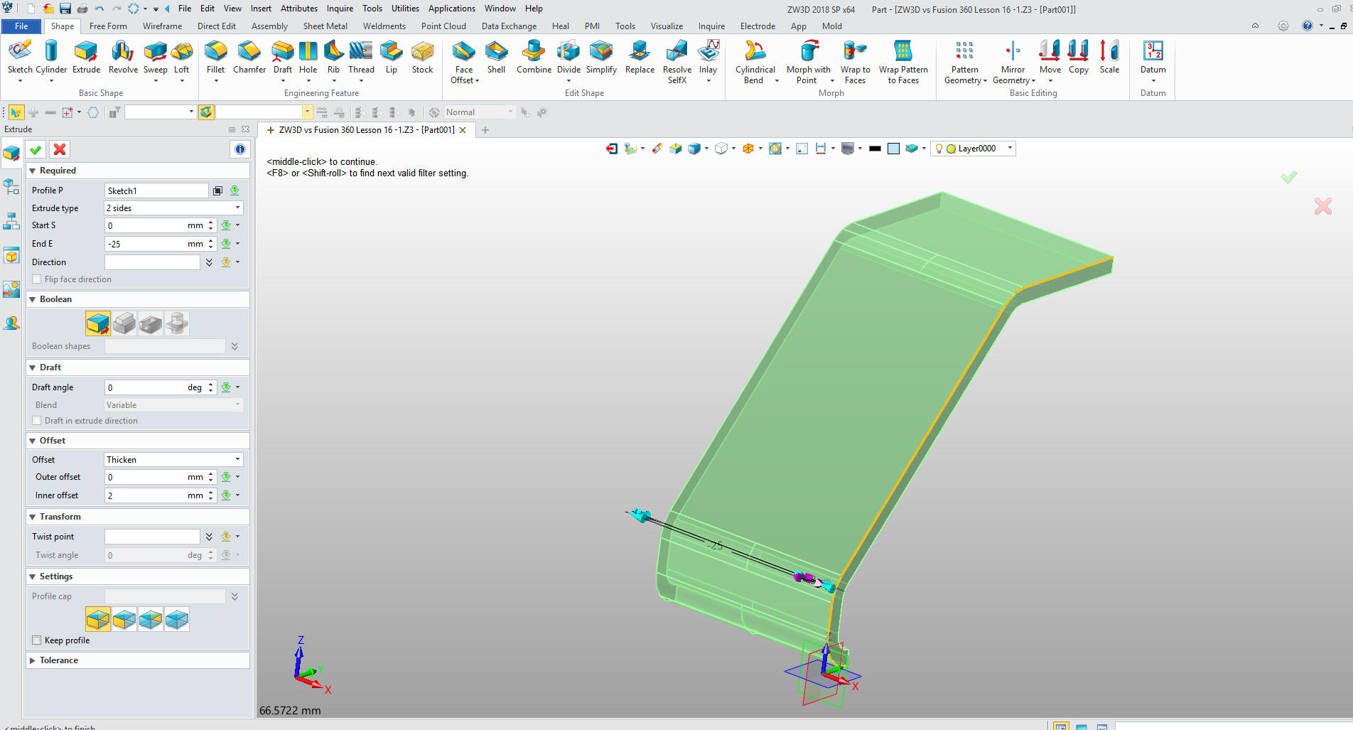
I had
my ZW3D guru, Phil Procario, take a look at this model and he showed
me a short cut. Instead of offseting the profile he said we could
thicken it in the extrude command. Very cool indeed.
Note:
ZW3D is the only system that has integrated solid modeling and
surfacing. Surfacing and Solids were designed to use the same
commands. Unlike the Solidworks clones, surfacing being a clunky
add-on and Rhino where Boolean solids were added later.
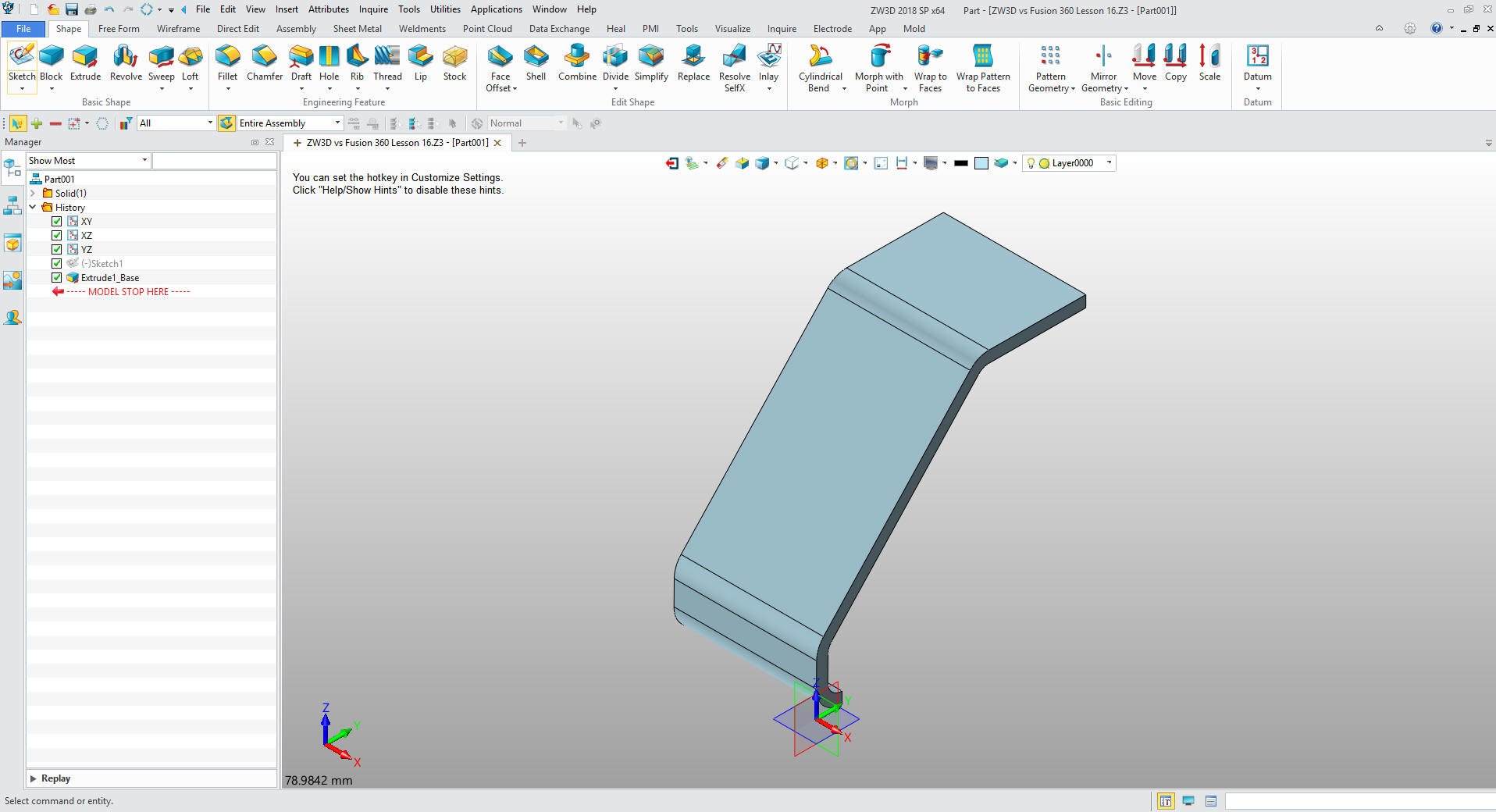
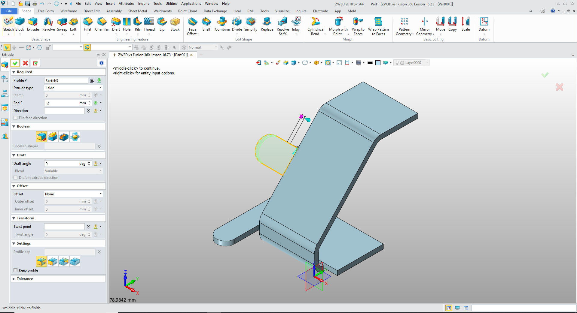
We now
have our bent shape.
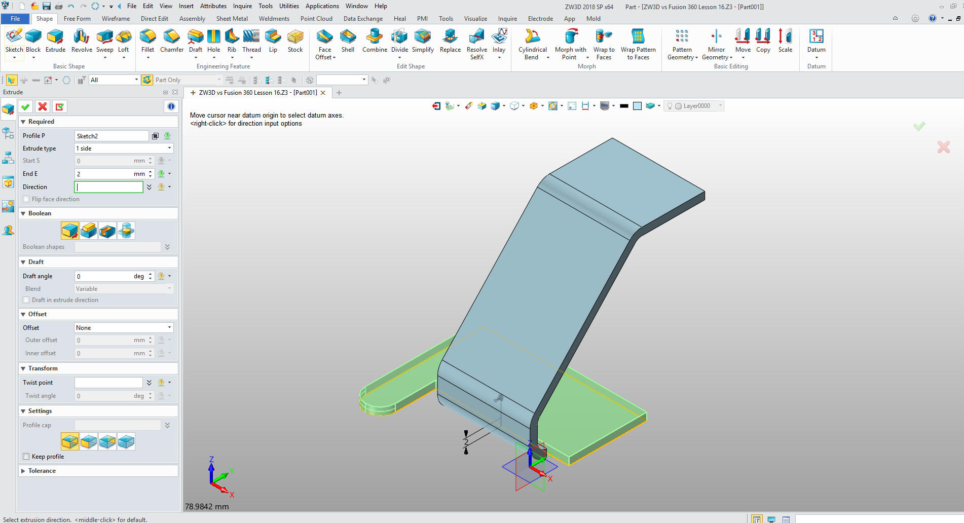
Now we
will create a sketch on the X-Y Plane and sketch the bottom plate
using Streamlined Sketching.
We
extrude the sketch 2mm adding the shape.
We now
have basic sheet metal part.
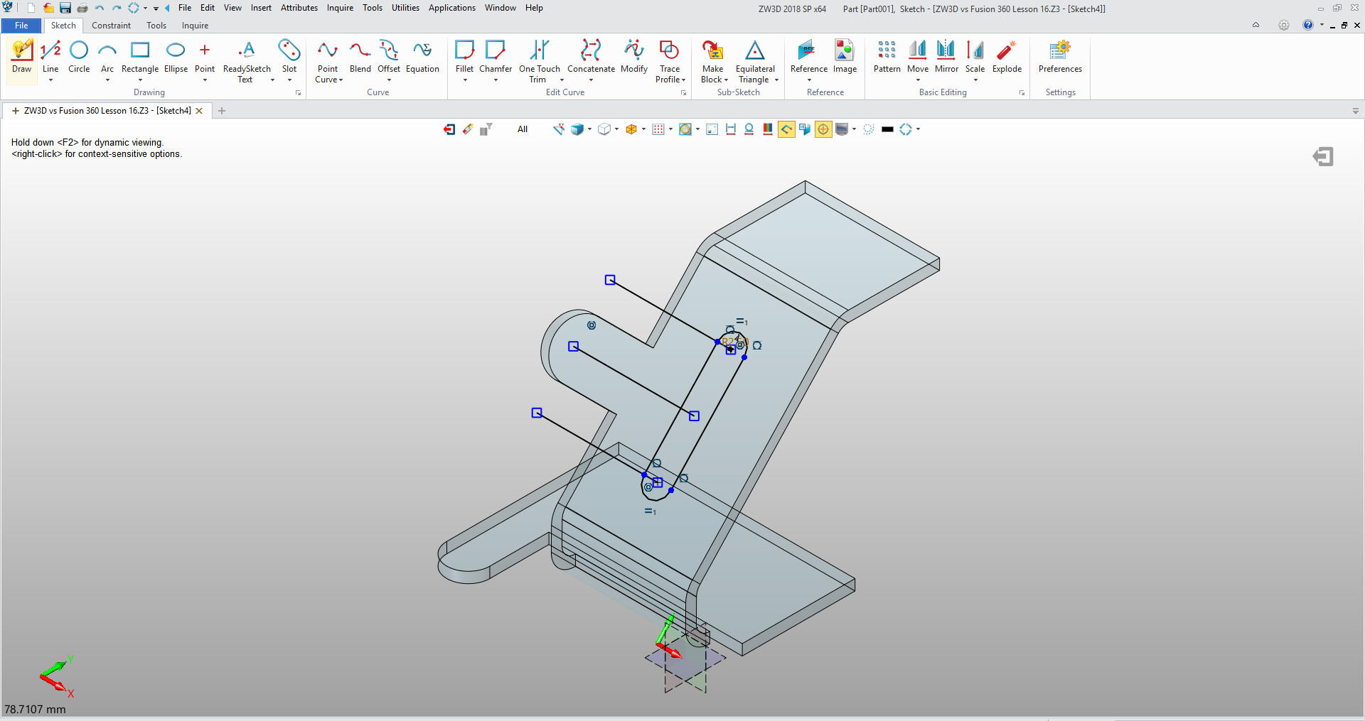
Now
create a sketch on the middle face. We go to the sketching mode. I
slightly rotate the view to get to the reference entities. I use
Streamlined sketching to create the tab. Notice I do not need to use
constrained dimensions.
We
exit the sketching mode and extrude the tab and add the shape.
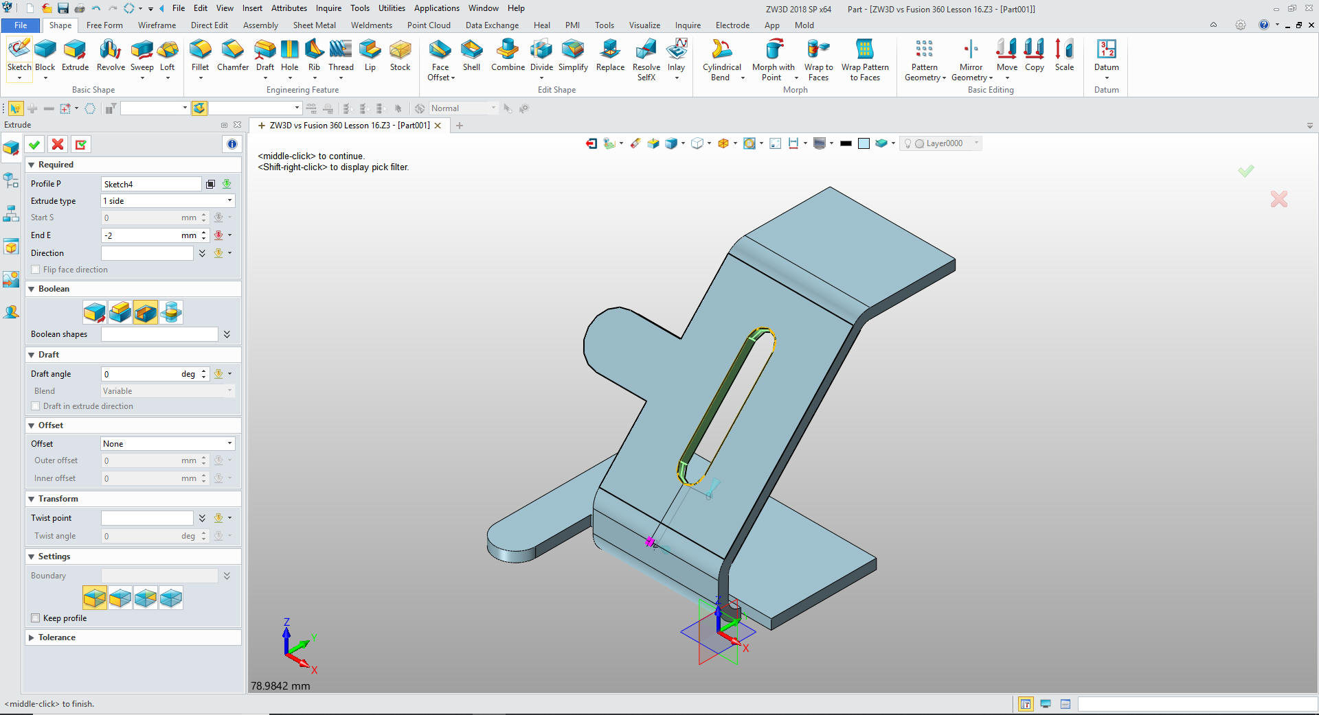
We
again create a sketch on the front face and add the slot. I have
left the construction entities to show you how Streamlined Sketching
works.
We delete the construction geometry and exit the sketch mode and
extrude the slot and remove.
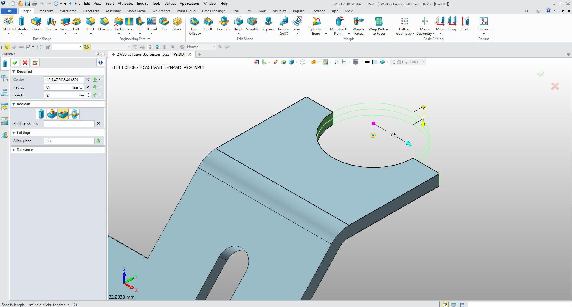
Now for the top radial cut. We
select a cylinder from the primitive shapes and locate and size the
cylinder and set to subtract. This is Feature Based Modeling. There
are a few CAD systems that have this. You want to learn it. It is
quite flexible and productive.
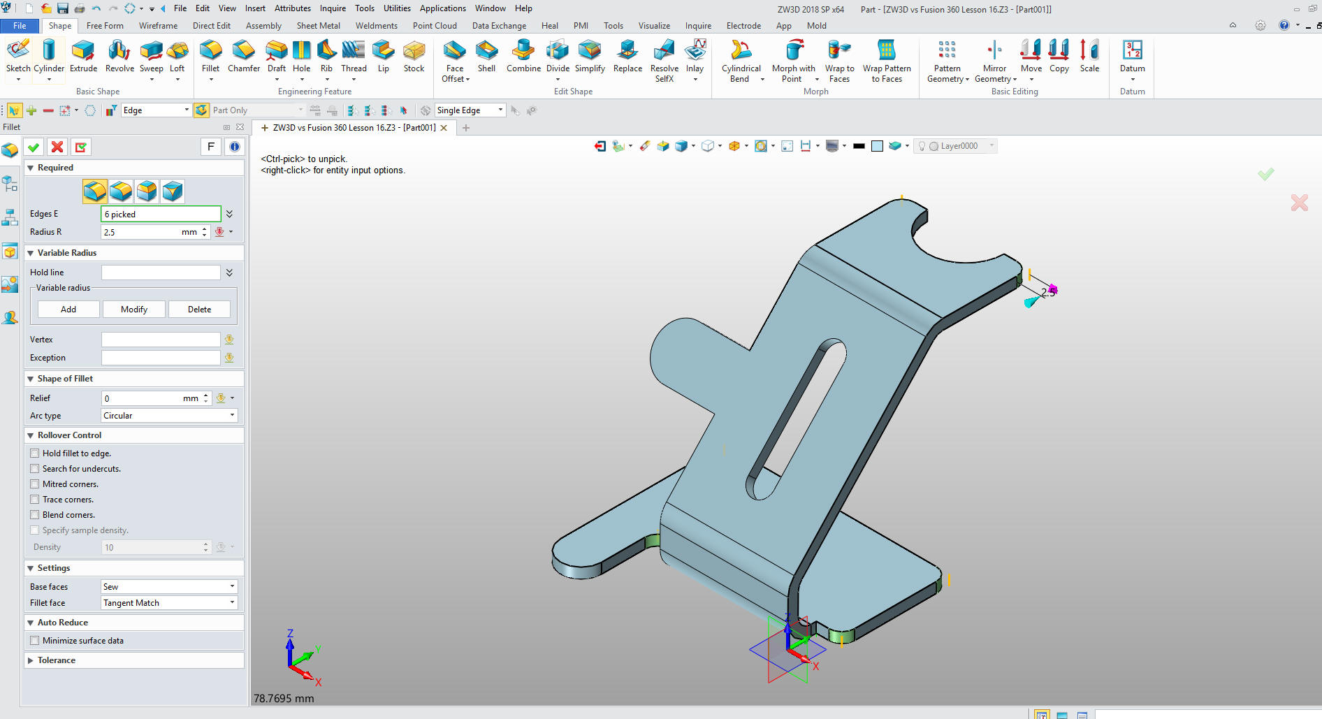
We are
pretty much done. Now
we add the fillets.
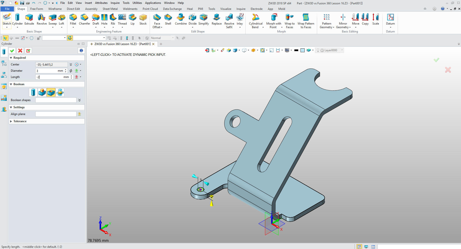
Add
the two holes by inserting primitive cylinders and setting them to
subtract.
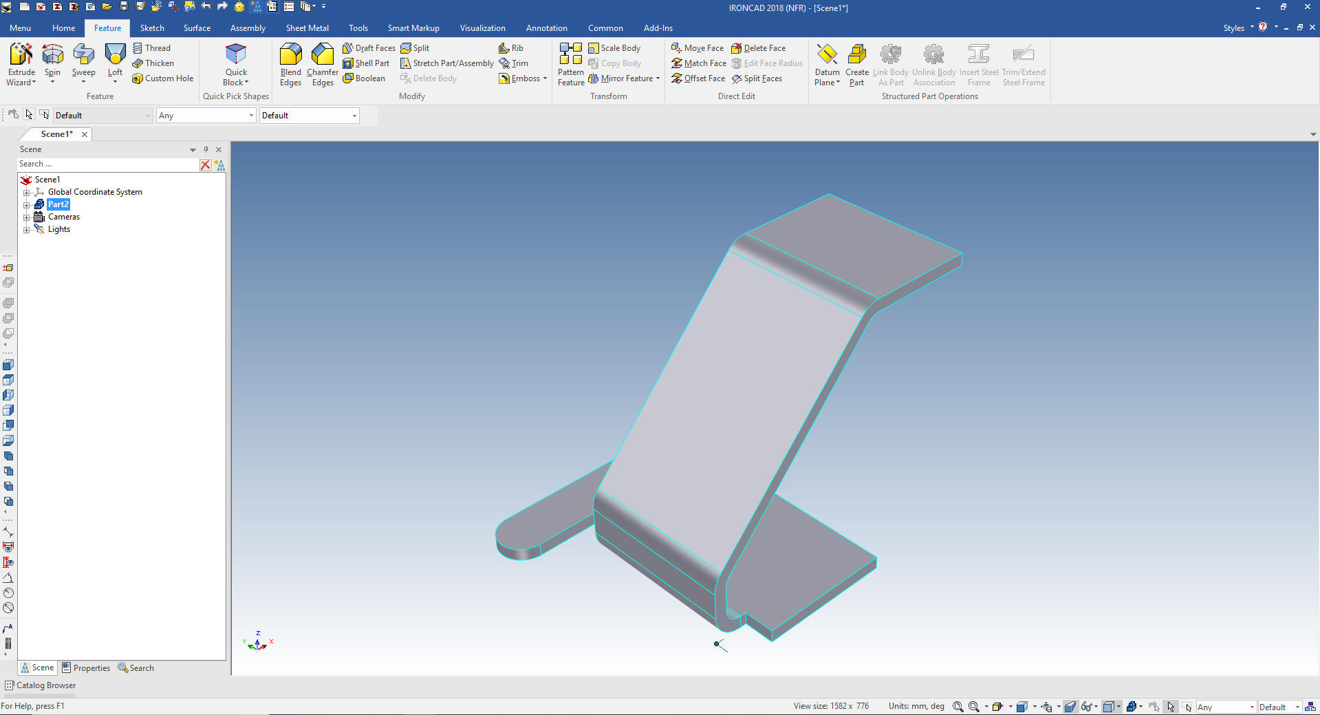
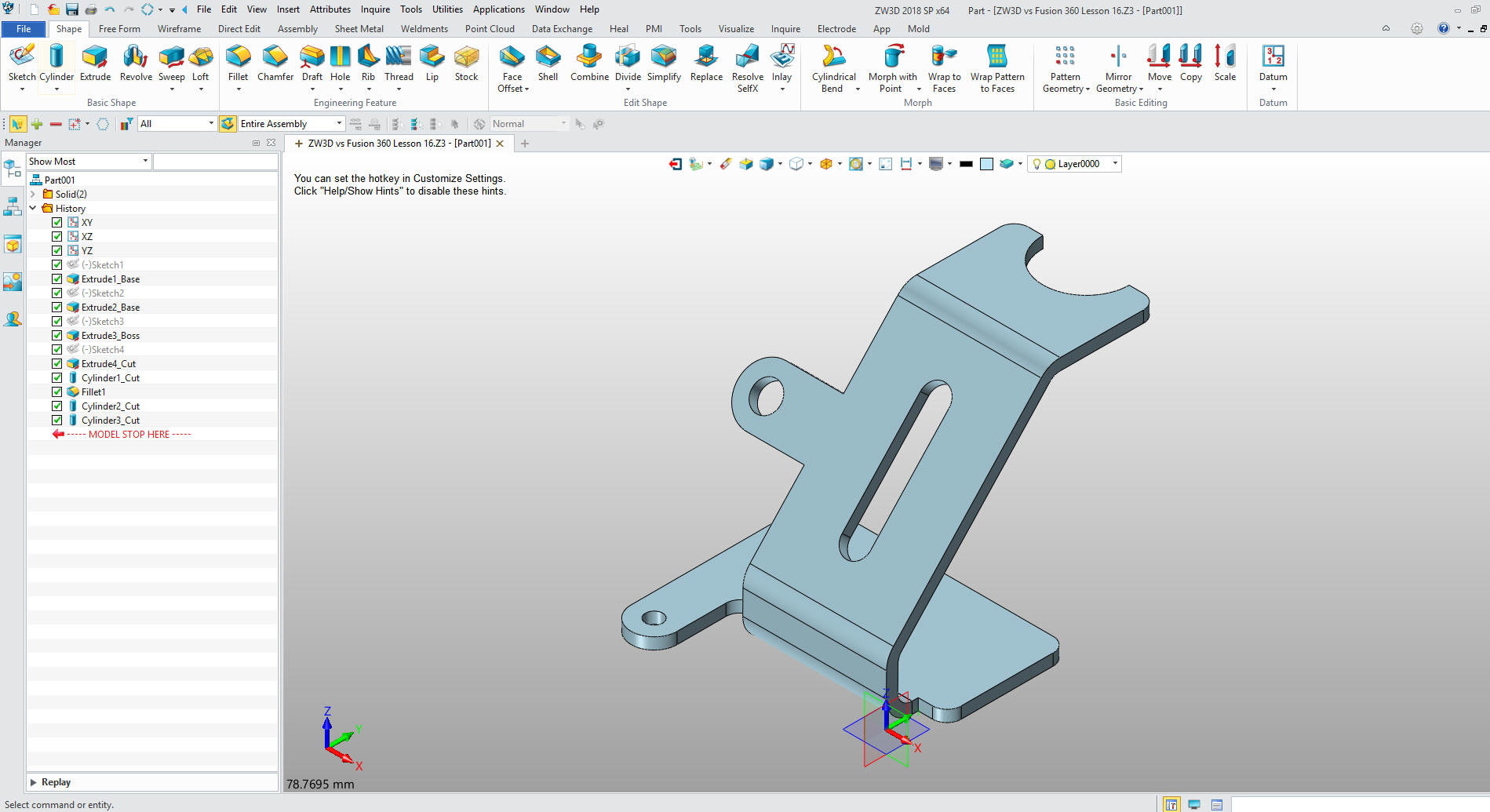
We
are done with the part. Even by creating the model this way was
faster than the Fusion 360 presenter with the sheet metal module.
ZW3D is one of the few 3D CAD systems that has integrated AID
(drawings) you just select 2D sheet and create your documentation.
With its multi-object environment you can do complete projects in
one file.
Now we will detail the part correctly. Of course, we cannot really
detail a part by itself. We need to have the assembly so we can
define relationships of the features so both or more mating parts
align. So I will just defined the part so it can be understood by
manufacturing and those that may want to create the model.
Now you Fusion 360 users,
use
this drawing to create the model with the sheet metal module. You
will quickly see that the sheet metal module is a bit clunky and
time consuming. If fact he didn't even use the correct dimensions.
When converting drawings to 3D you have to redetail the part to
assure it is the same as the drawing.
Now let's build the model again using the correctly dimensioned
AID (drawing)
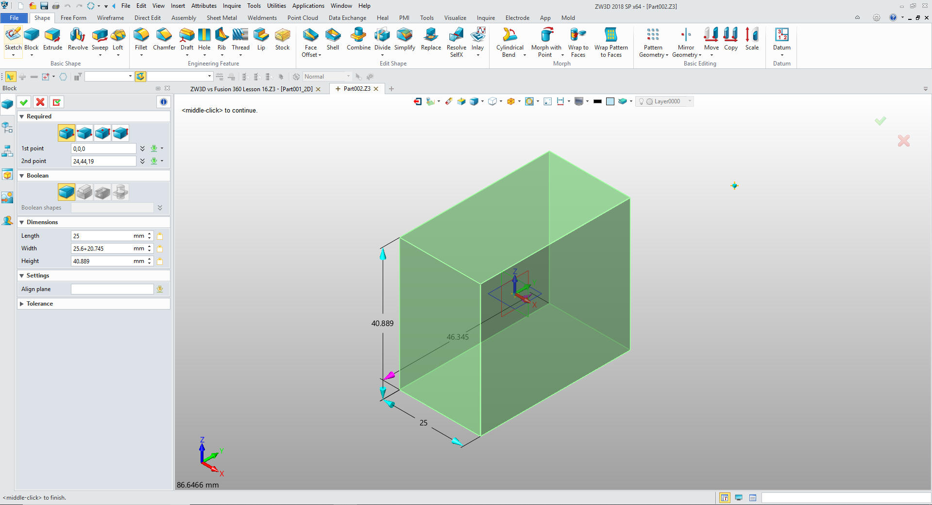
We are already in mm so we will create a
primitive block and size it.
Note: ZW3D offers the primitive
shapes as part of your design options. As you get familiar with the
process it increases your productivity relieve much of the tedious
constrained sketching.
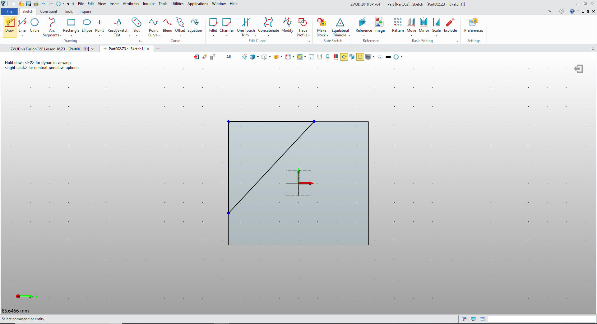
I will
use Streamlined Sketching, which means I will not use constrained
sketching. I offset lines from the relative edge to create the ends
for my diagonal line.
I put
in the diagonal line and horizontal and vertical likes defining our
cut. I delete the two reference lines.
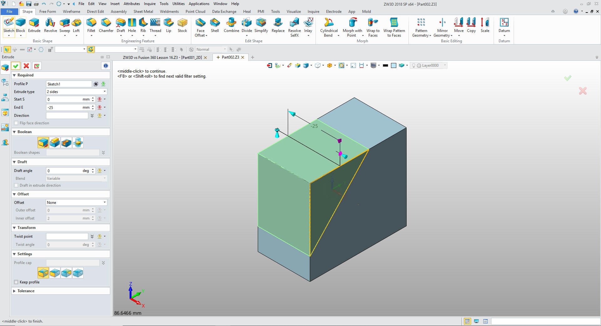
I exit the sketch mode and extrude the profile.
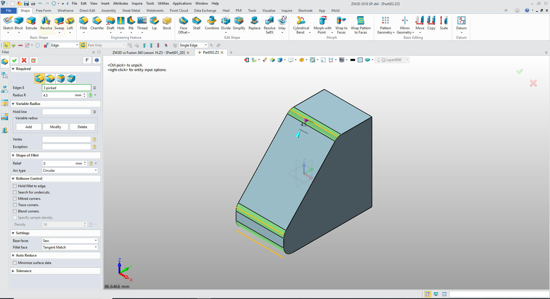
Now we
will add the BR of 2.5mm plus the material
thickness and create the 4.5mm blends
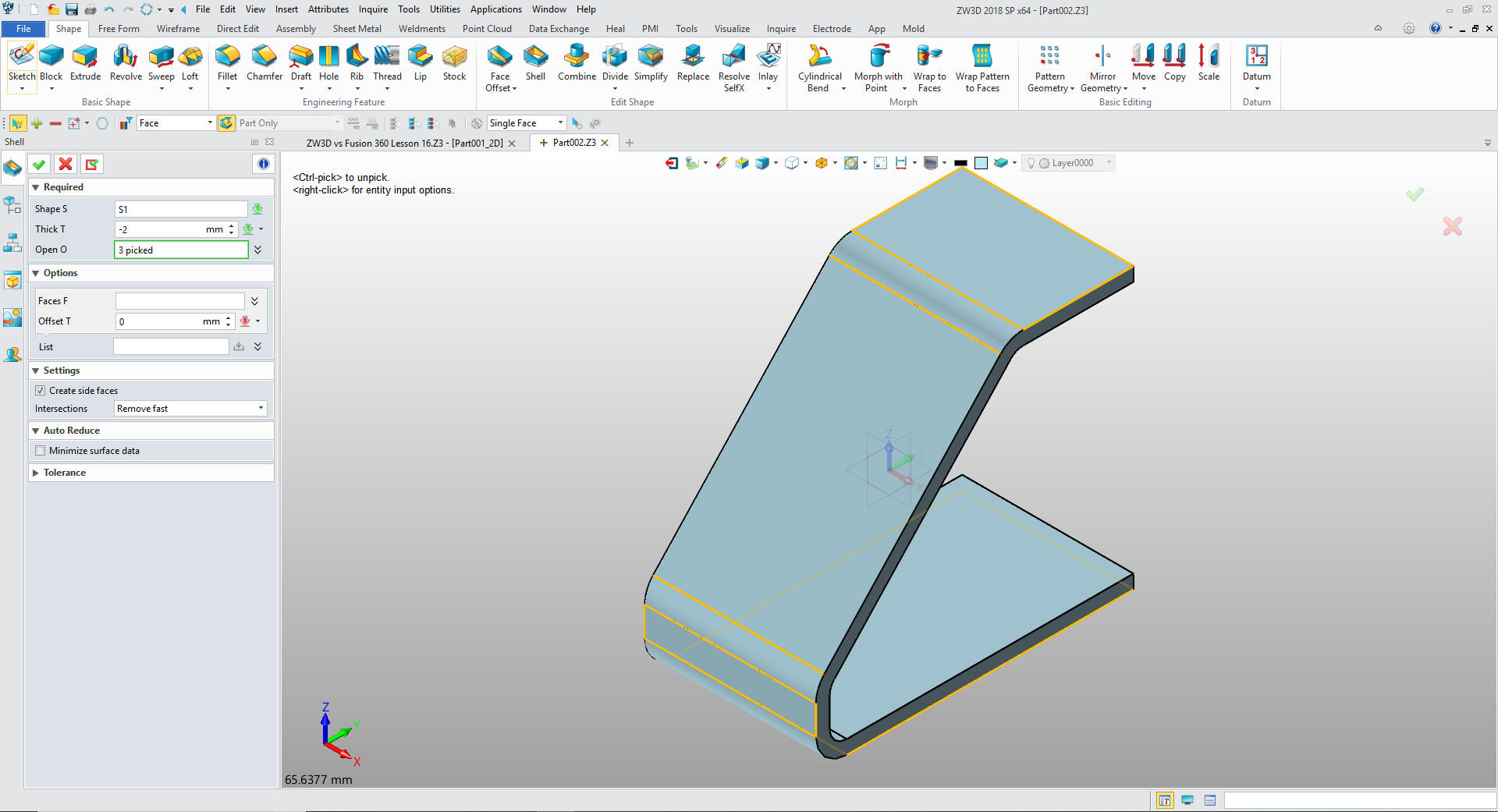
We can now shell the part. I could sketch the cut but this is so
much faster. Shelling is a big part of sheet metal modeling. I
select the three open faces and set the shell to 2mm. When you
design sheet metal you are working on overall shape that may be difficult to create with the sheet metal program. I just
want to make you all aware that it can be done a different way.
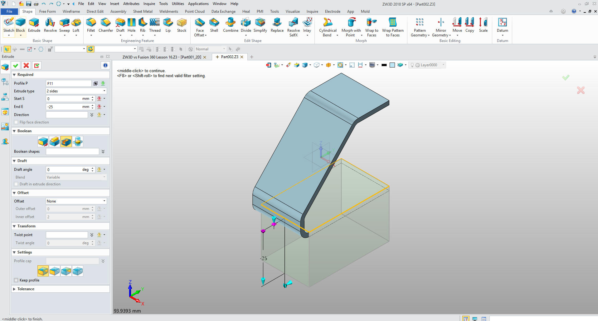
We
select extrude and select the bottom face and eliminate the flange.
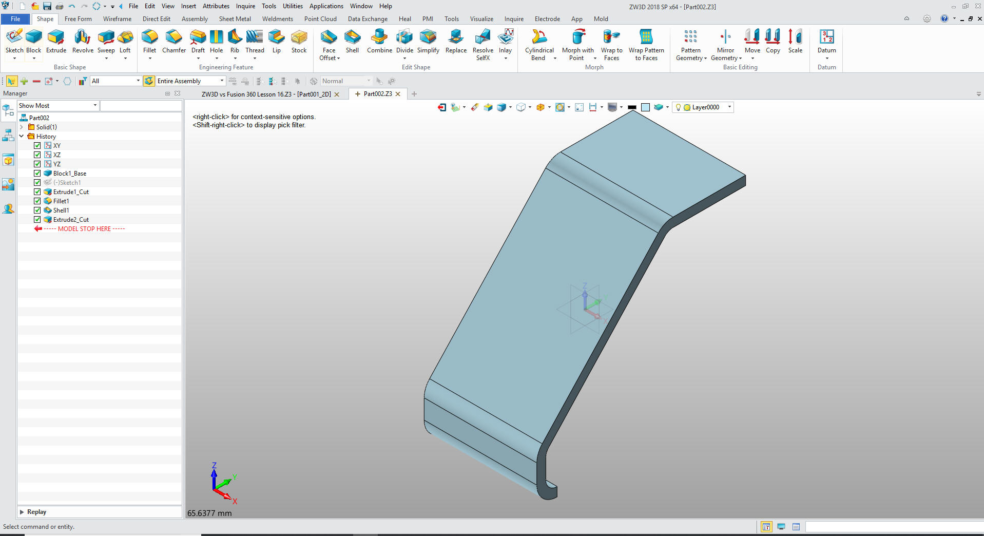
Now we
have the bended shape.
Like we did above, we
will create a sketch on the X-Y Plane and sketch the bottom plate
using Streamlined Sketching.
We
extrude the sketch 2mm adding the shape.
So there you go. That is how we
modeled sheet metal parts in the past and I still do.
It is
very important that you look into how you or your engineers are
creating the parts. Streamline Sketching and Feature Based Modeling
is easy to learn and implement. It, alone, will increase
productivity 10X. Now, IronCAD with its unique integrated
history/direct edit functionality can increase your productivity
another 5X or more with changes! Again, time is money in
engineering.
More on Streamline Sketching and Feature
Based Modeling.
To experience this increased level of productivity, please download
IronCAD for a 30 day evaluation. Legacy data is no problem, IronCAD
can read the native files of all of the popular programs. IronCAD is
a great replacement for the subscription only Autodesk and PTC
products.
Give me a call if you have any
questions. I can set up a skype or gotomeeting to show this part
or answer any of your questions on the operation of IronCAD. It
truly is the very best conceptual 3D CAD system.