IRONCAD vs Fusion 360 Lesson 16 3D Modeling Techniques Defined
Alternate Sheet Metal Modeling Streamlined Sketching/Feature Based Modeling
The modeling technique is
hugely responsible for the level of productivity. Those of you that
are only trained in the sketch, sketch, constrain, constrain world
are truly limited by not using the freedom of Streamlined Sketching
and Feature Based Design,
that is available in even the most Pro/e-ish of CAD systems. If your
designers are designing in these very unproductive and time
consuming processes it might be time to review your standard design
processes. Don't have any do you? When I introduce IronCAD's very
flexible design paradigm I have a hard time to get the Pro/e clone
users, like Solidworks and other programs to understand the drag and
drop design paradigm.
Download
IronCAD/Inovate and take
the one day and 17 lesson course. I get rave reviews from my new
customers. Give it a try, this is a fully functional 30 day
evaluation with all of the native translators so you have access to
your legacy engineering information.
IronCAD Self-Pace Training Course I am available for support questions and presentations on Skype
from 4 am until 3 pm most weekdays and 4 am to 9 am on weekends.
Fill out the download form and ask for my Skype or give me yours so
I recognize you.
This kind of support continues if you
become one of our users!
I saw the
following video challenge on linkedin and thought I would give it a
try. I actually did it before I watched the video, so I
did it a bit differently. This will give you an idea how different
and flexible IronCAD is compared to the conventional Pro/e clone and
to the not so conventional Fusion 360.
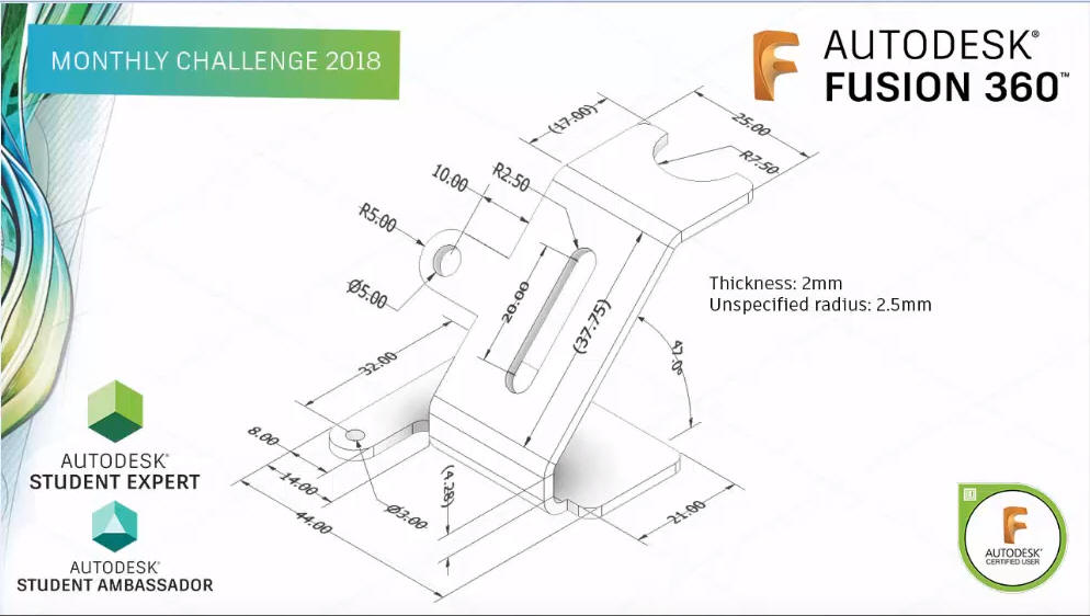
Look at this drawing. Who details like this? It is obviously
dimensioned only to be able to easily create a sheet metal model with
the sheet metal tools. No where in the world would they detail a
drawing like this. How do you inspect it? We are going to get it
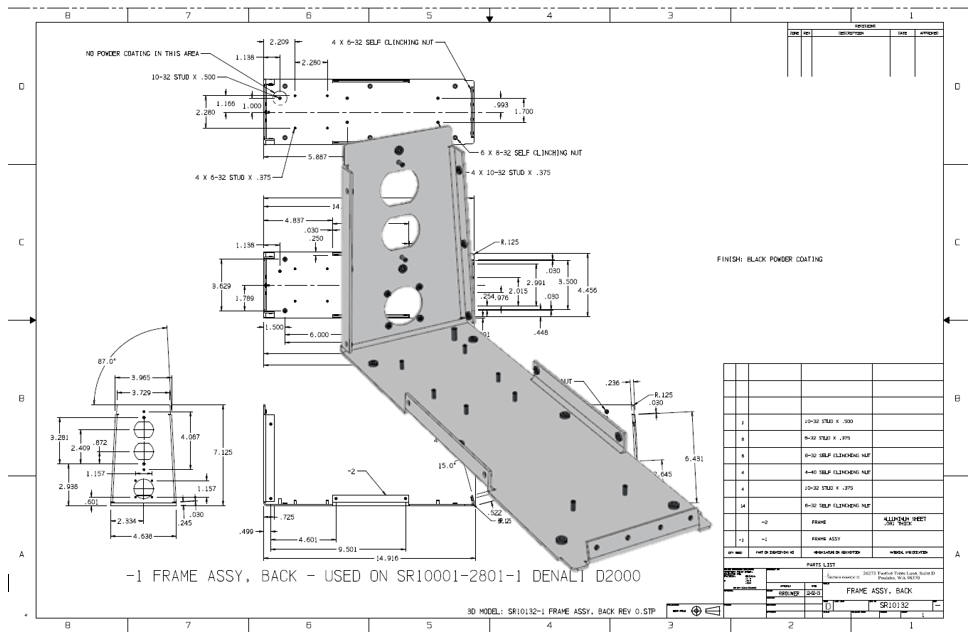
back to reality. I have included a
properly detailed drawing below.
Alternative Sheet Metal Design
I was introduced to
3D CAD in 1982 with Computervision CADDS 4, Found PC base 3D CADKEY
at Boeing in 1986, Started using and selling it in 1987. This was 3D
wireframe, no fancy sheet metal modules. We even had unfolding
programs for the wire frame design.
Here is an image of a
wireframe sheet metal part. With CADDS 4 we started with one color!
Green on Black! They added Color for $35,000 per seat with CADDS 4X.
I sold PC Based 3D CADKEY in 1987 with full color with 90% of the
functionality of CADDS 4 and Catia 2 for $9000.00 with CADKEY, a 386
computer and 19in CRT. CADDS 4 and Catia were well over $100,000.00
per seat.
Are you looking up or down? This used to drive the engineers
crazy. Yes, in those days 3D CAD was only in the realm of draftsmen!
Enter solid modeling in
1995. We started modeling our sheet metal like we do all of our
models. We would develop the basic shape and use shelling
command. I show this process below
I am afraid that many of the new millennial engineers really don't
know you can probably do your sheet metal design faster and easier than
with the sheet metal modules. This option probably has never been
presented.
Now, I suppose if I only designed
sheet metal parts a sheet metal application might be advantageous. But most of us design
projects where a variety of mechanical design is used. Machining,
sheet metal and other fabrication. So you may design just a few
sheet metal parts.
Being a Boeing trained draftsman, I have
extensive sheet metal design experience. We would do flat
pattern development on undimensioned drawings to .005 tolerance.
They would photograph the flat pattern to create the tool.
Today, I
just use the basic solid modeling tools. In IronCAD I may grab a feature from the sheet metal
module, but that is it.
Here is a website that gives the
basics of sheet metal design!
While creating 3D models from drawing is the very best
way to learn 3D CAD and maybe some design techniques is does not
expose the designer to the design flexibility necessary in product
design. IronCAD is all top down due to the single model environment.
Creating mating parts is a cruise. But modeling is just one aspect of a
well designed productive 3D CAD system.
I would do a
video, but I really am not good at it. So I will show you step by
step. I will try and get IronCAD support to create one. They are
very good.
I always create the part before I watch
the Fusion 360 Video, so as to not taint my process. Of course,
there are a multitude of ways to create a model. There is no right
way, just more productive ways. From what I have seen from these
very complicated processes done by the Fusion 360 fellow, it is not
just limited by the 3D CAD system.
Creating this model without
using a sheet metal module would be a snap if someone understood you
just don't dimension parts for the sheet metal module. So lets get
started.
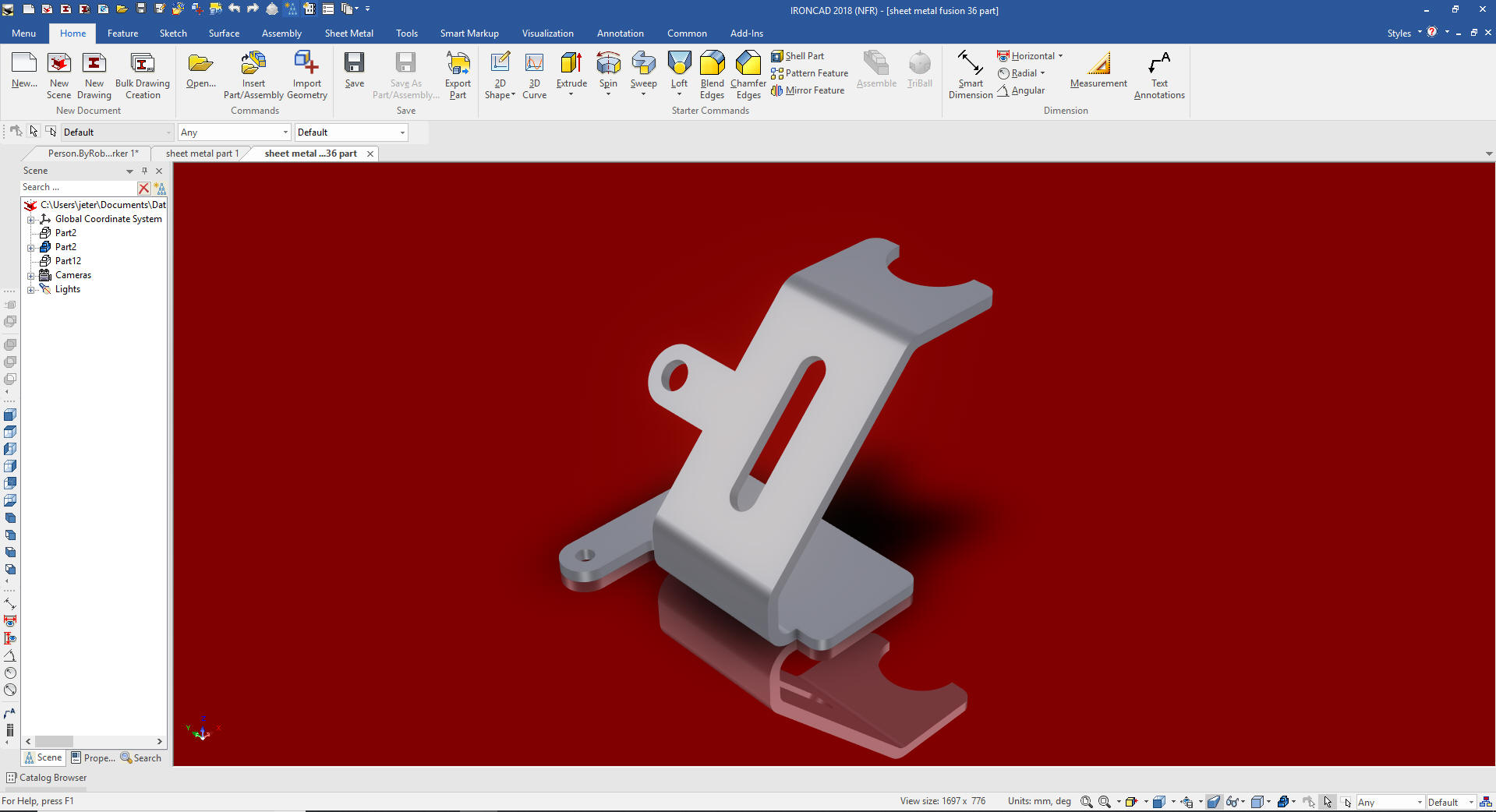
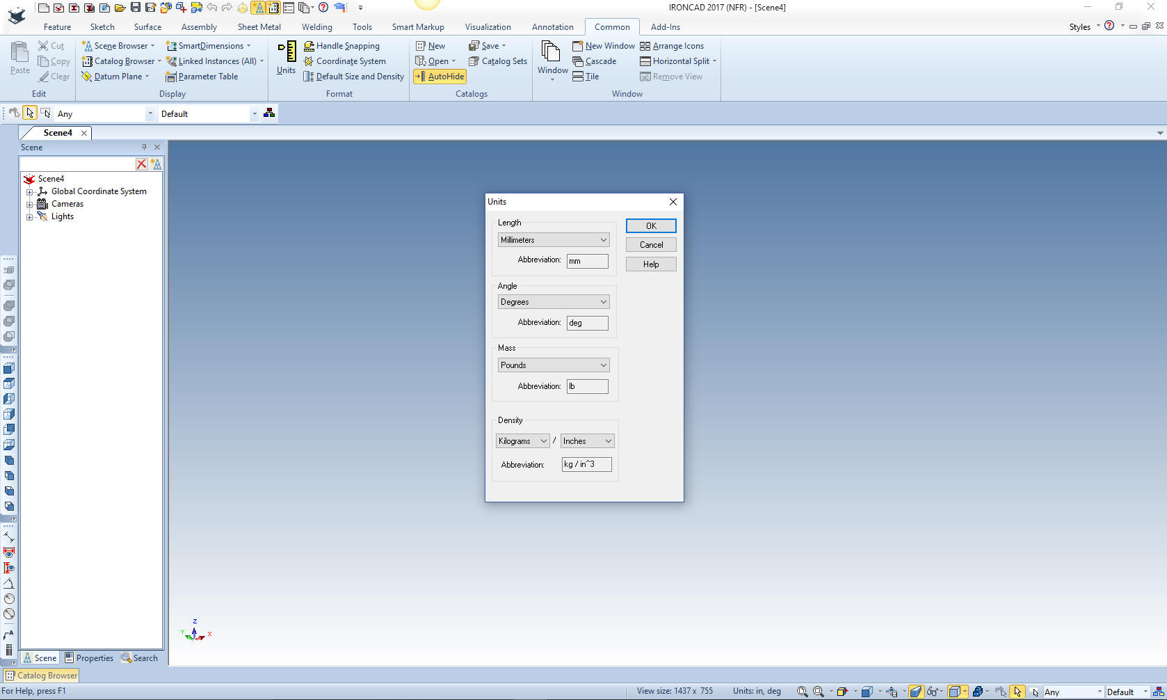
Here is IronCAD. My default is inches,
so we will set the units to mm. Let's get started.
We have to use descriptive geometry to define the sketch. This shows how silly detailing a part this
way.
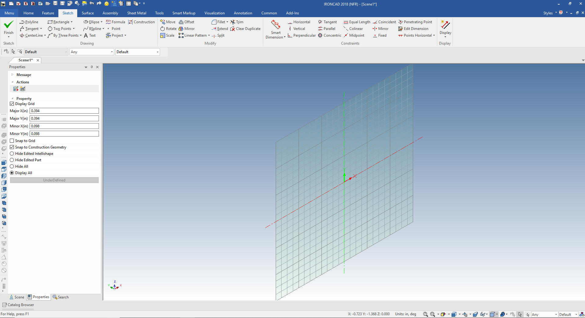
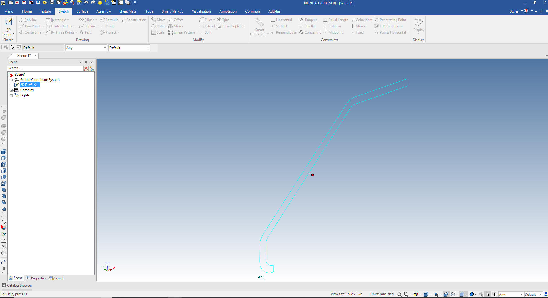
I first create a standalone sketch.
IronCAD has two sketching functions the Wizards that allow you to
instantly create a solid and the standalone sketch for more complex
sketching and .dxf/.dwg imports.
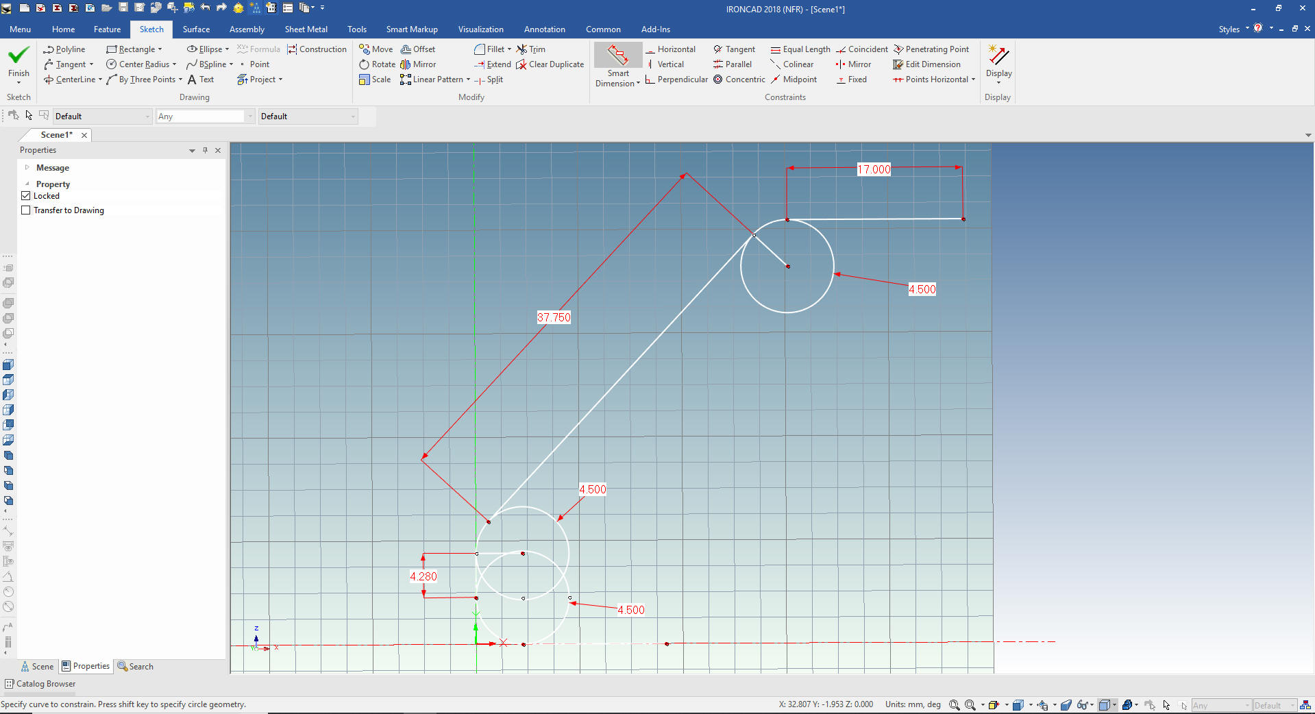
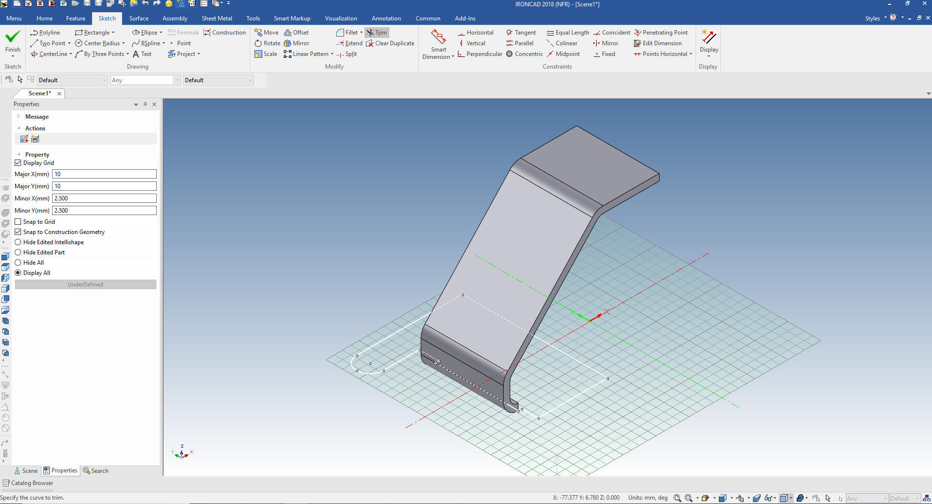
I
will just sketch the bent feature. Showing the geometry necessary to
develop the cross section from the drawing.
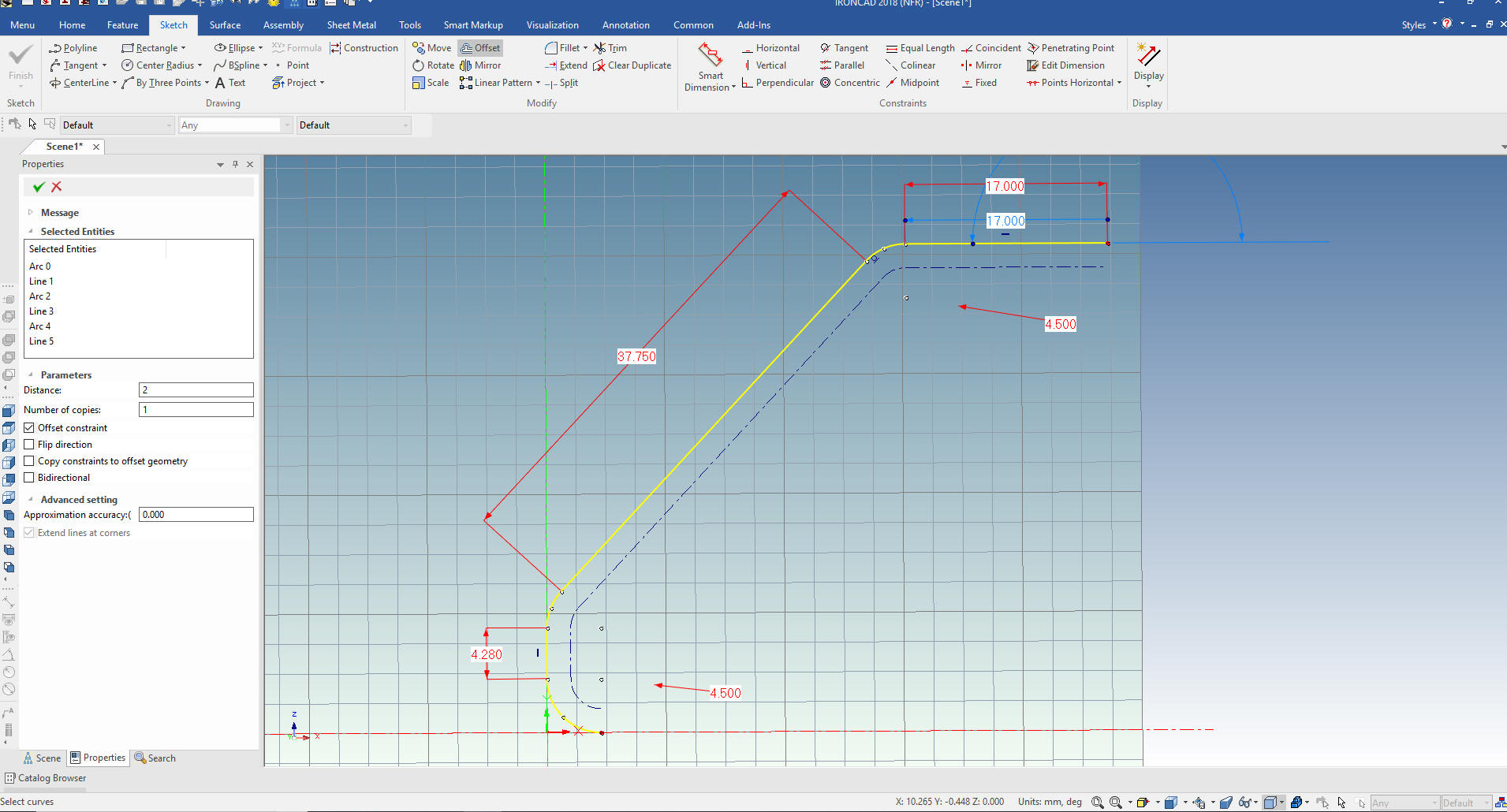
We
just trim the graphics and offset 2mm.
Add
the end lines and we are finished with the sketch.
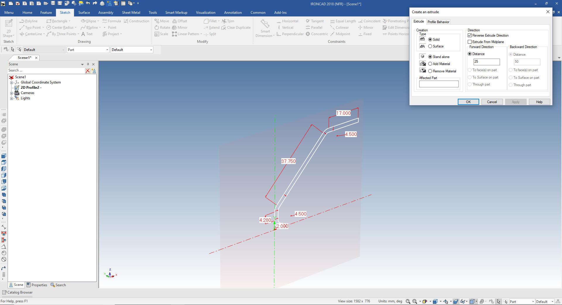
Now I
will extrude the the 25mm.
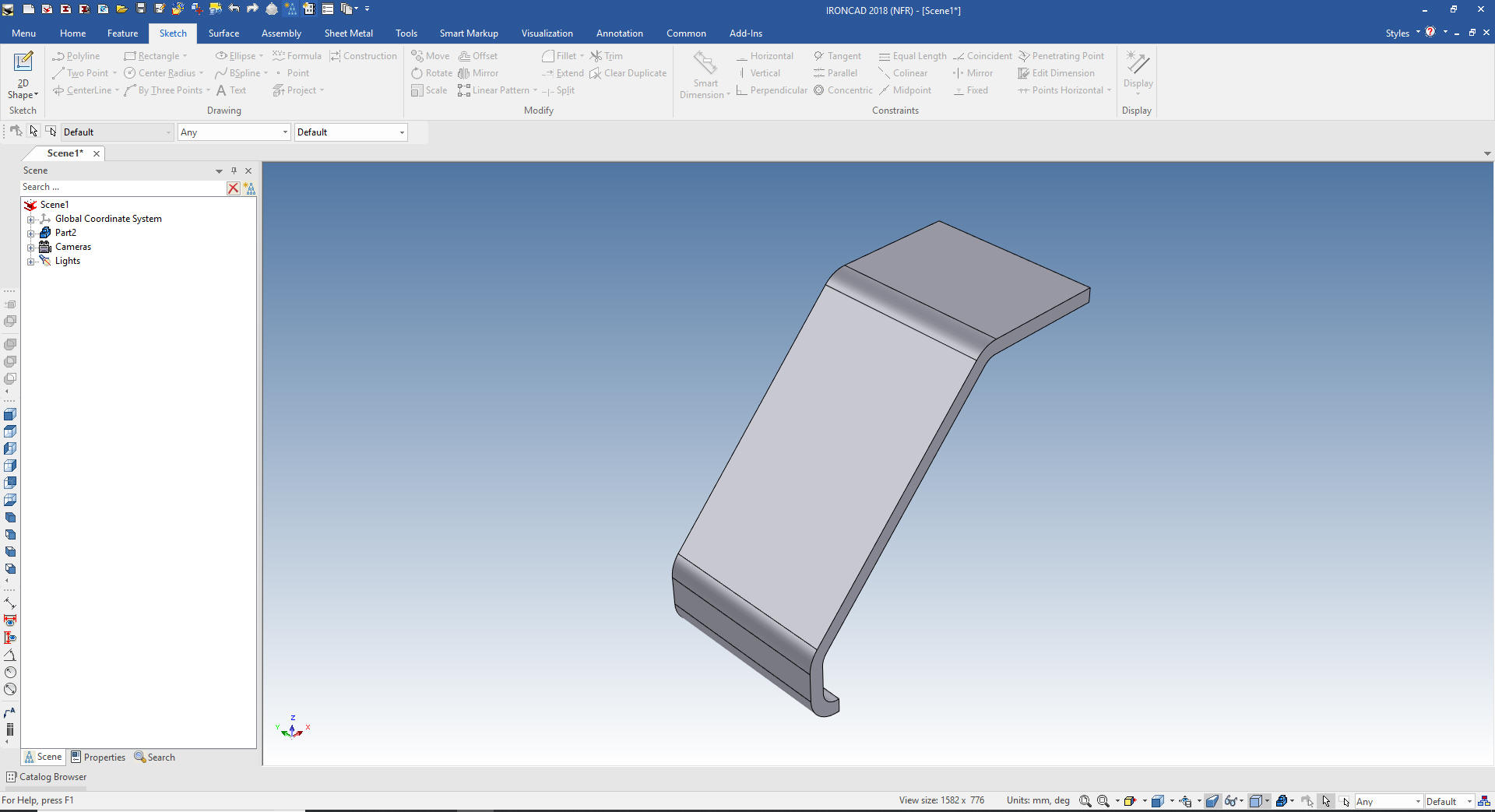
We now
have our bent shape.
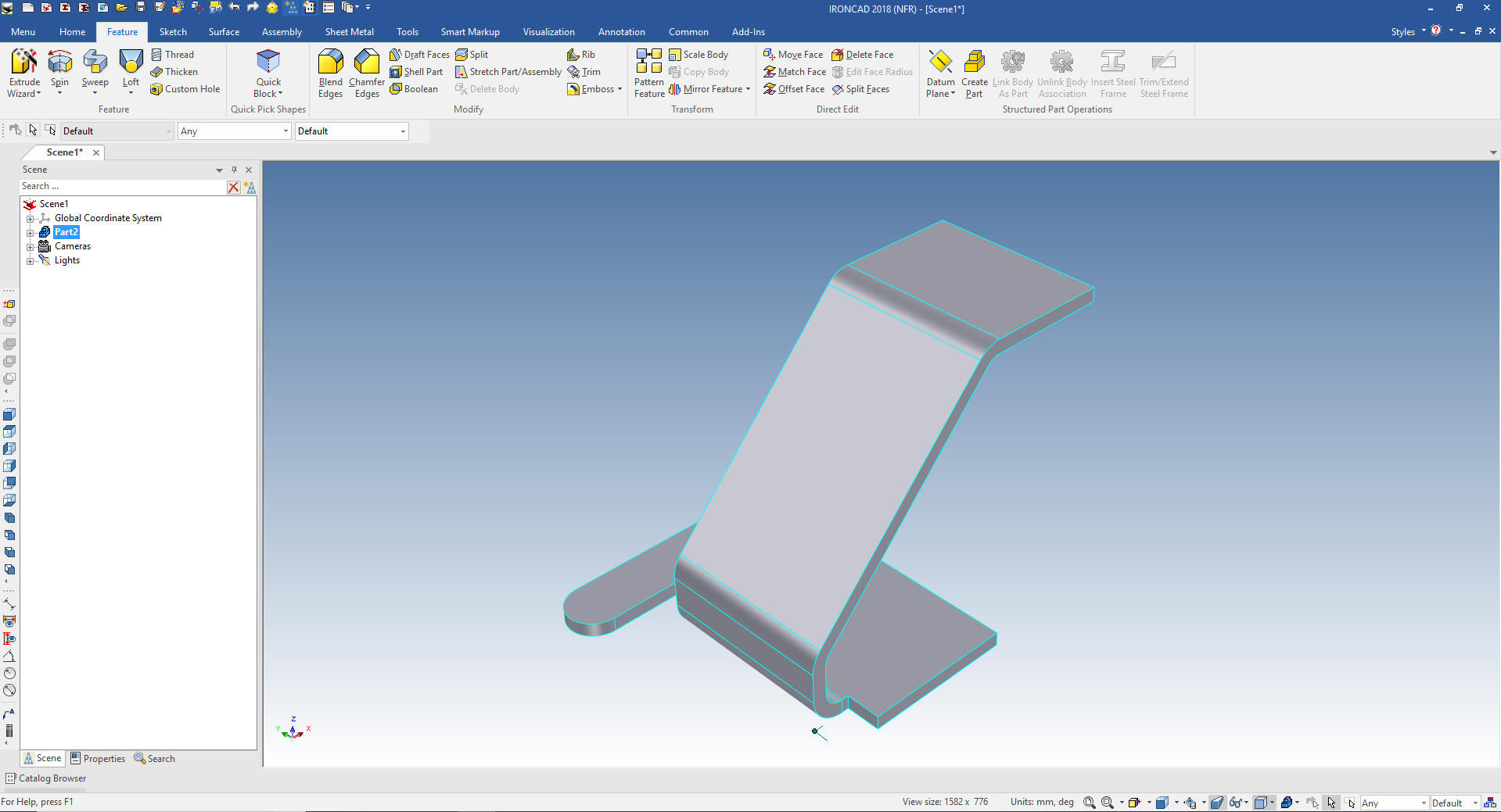
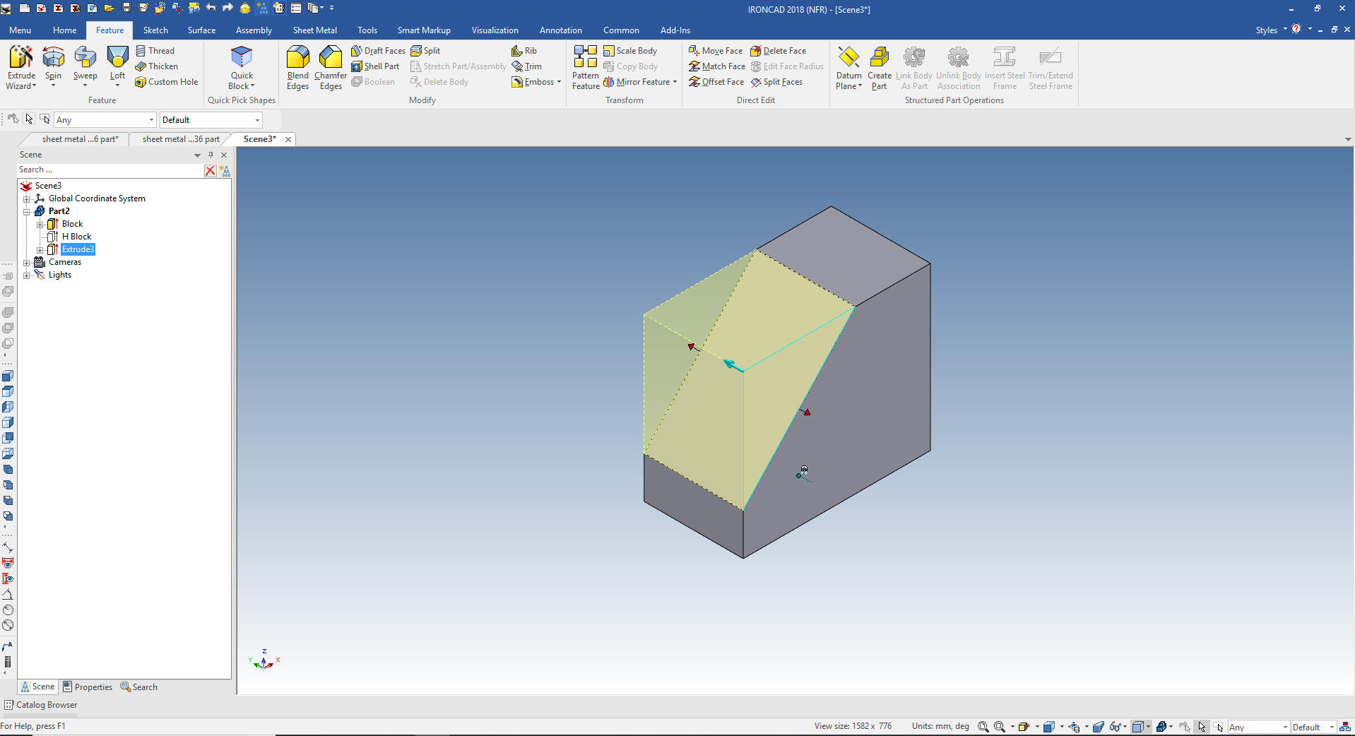
We
will now use the Extrude Wizard to create the bottom shape. We use
the top face to create the plane then the Triball to locate it on
the bottom.
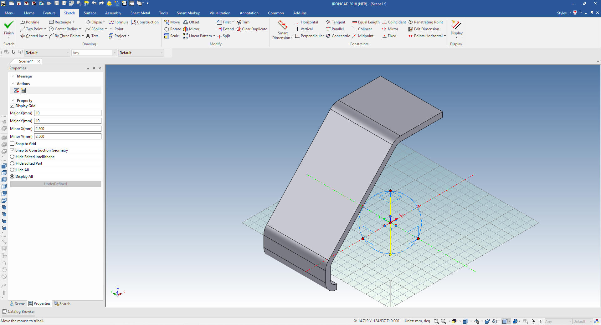
We
looking to the sketching plane and start sketching.
We now
have basic sheet metal part.
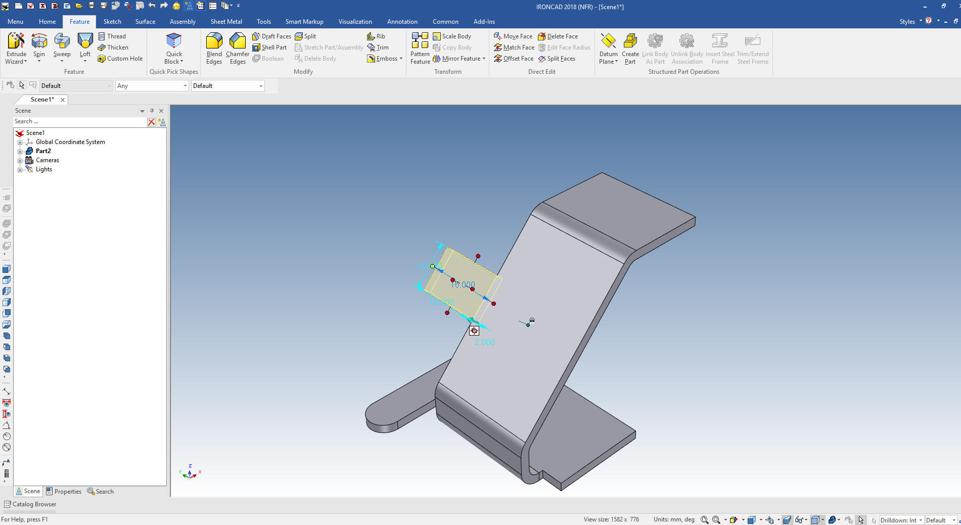
Now we
add the side tab by dragging and dropping a block and size it. We
have to assume a few things. I am locating it at the center of the
center face.
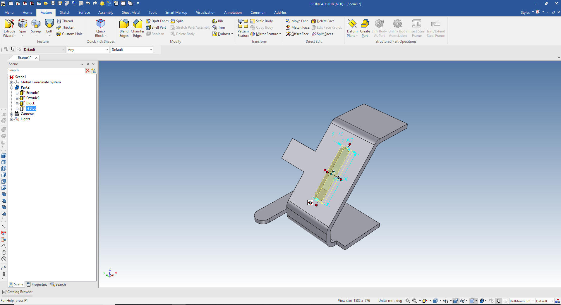
Now we
will drag and drop a hole slot the slot into the face. Again
assuming it is in the the mid-point of the face. IronCAD recognizes
edges, centers, mid-point and corners.
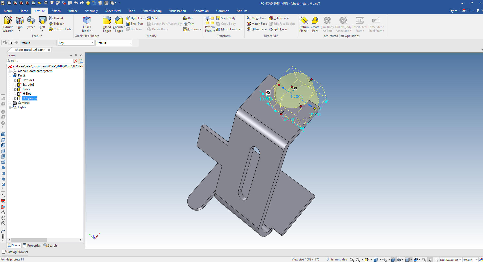
Now the top radial
cut.
Now for the top radial cut. We look at the top face and drag and
drop a hole cylinder on to that face and size it.
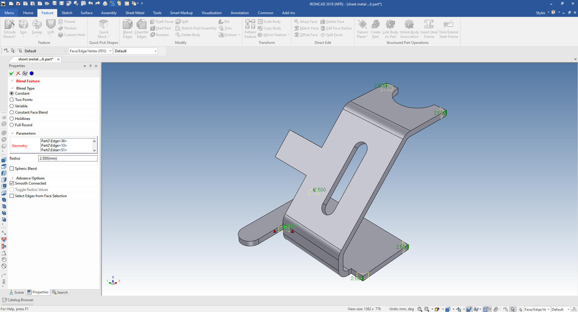
Now
we add the blends.
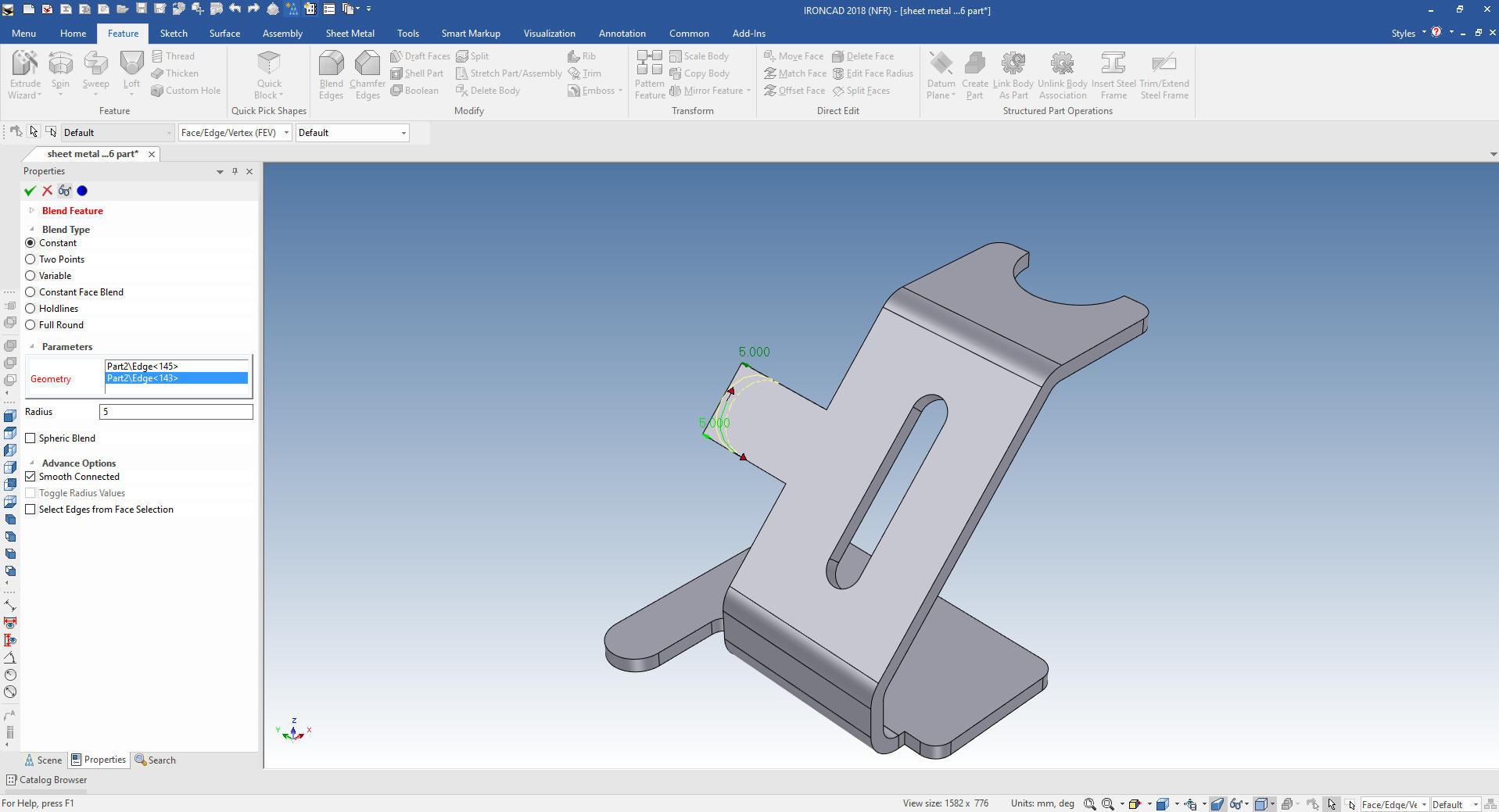
The
last blends on the tab.
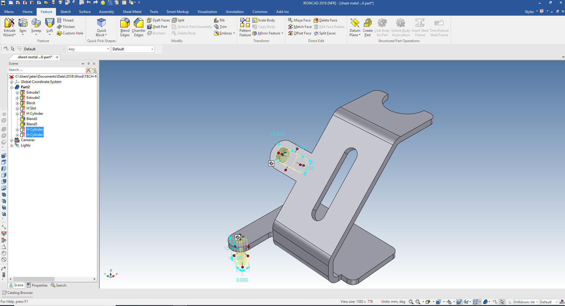
Add
the two holes by dragging and dropping hole cylinders to the center
of the radii and size them.
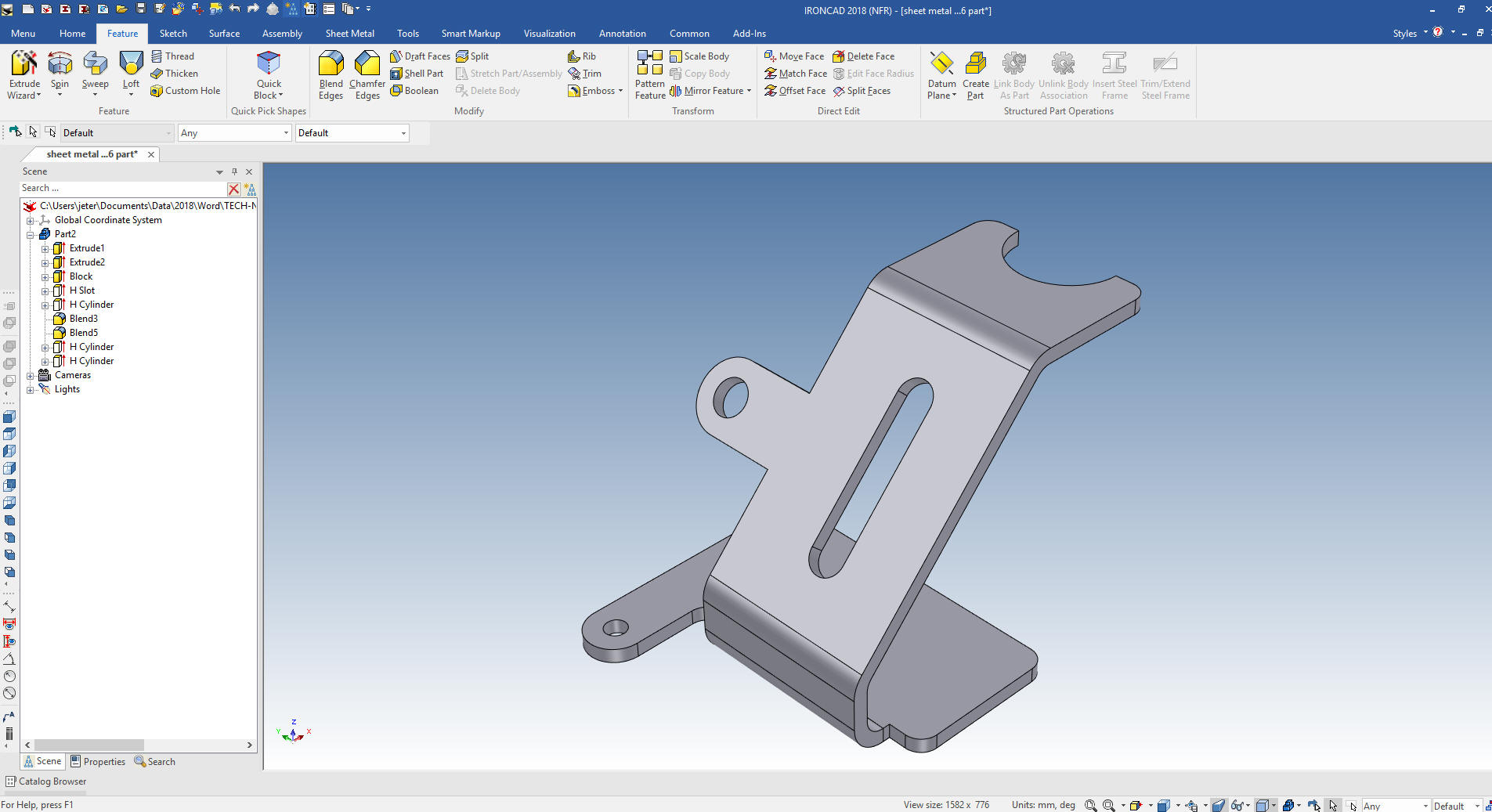
We
are done with the part. Even by creating the model this way was
faster than the Fusion 360 presenter with the sheet metal module.
Now you Fusion 360 users,
use
this drawing to create the model with the sheet metal module. You
will quickly see that the sheet metal module is a bit clunky and
time consuming. If fact he didn't even use the correct dimensions.
When converting drawings to 3D you have to re-detail the part to
assure it is the same as the drawing.
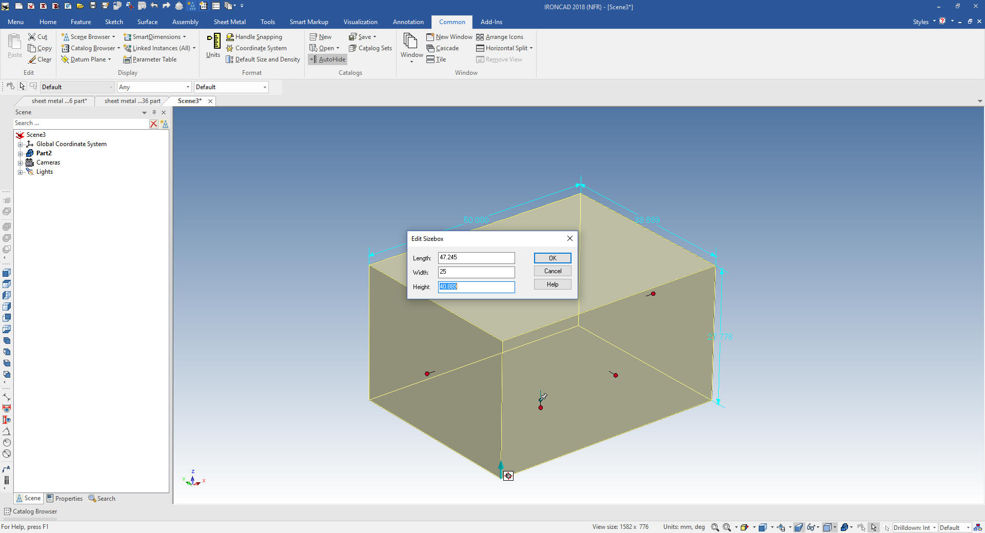
We are already in mm so let's drag and drop a
block and size it.
I will
show two ways.
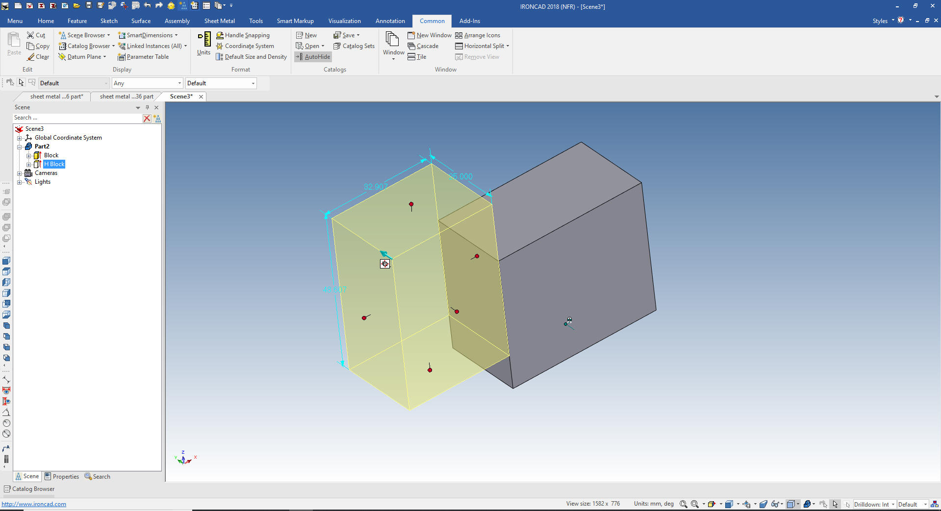
Drag and Drop design.
Now drop a hole
block onto the left face and push/pull it into position with the
handles. Notice it is just sitting on the affected face.
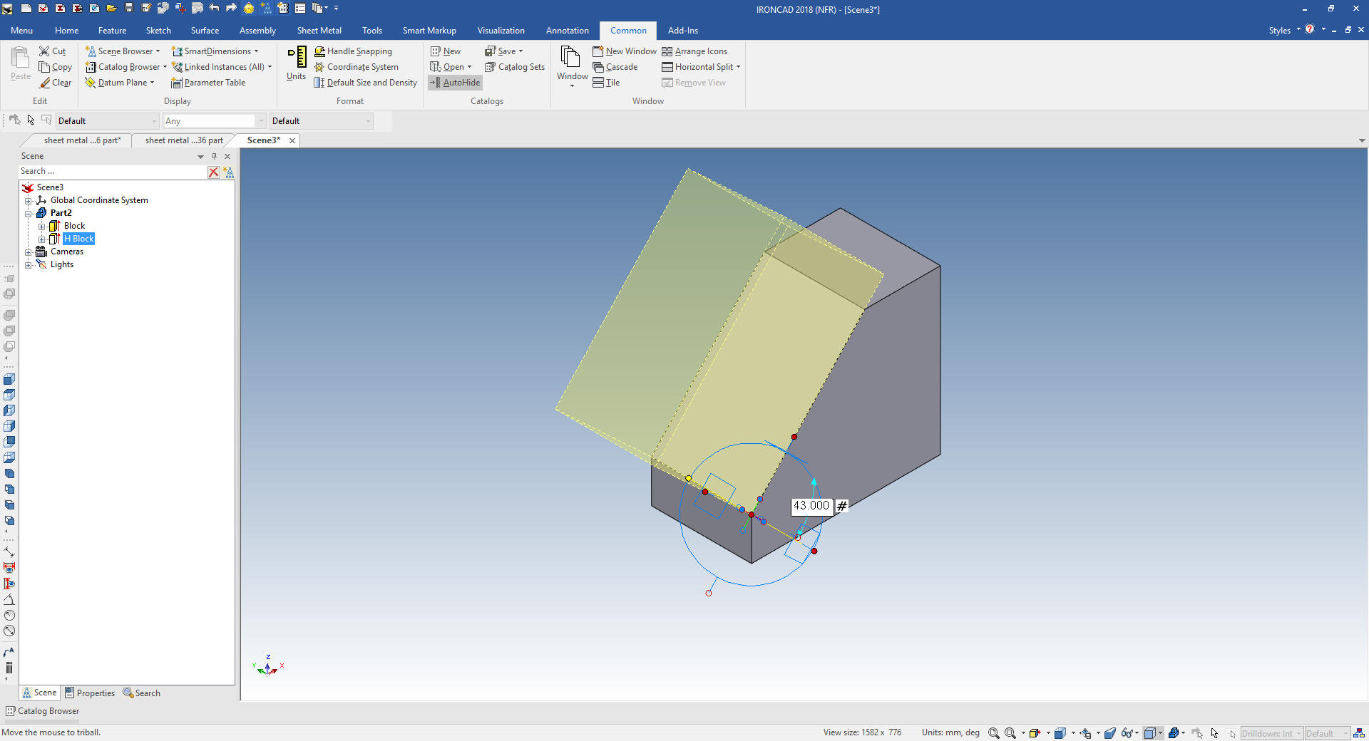
Now we
move the Triball to the edge and rotate 43 degrees.
Sketching
Now we can suppress that feature and I will create
a sketch. IronCAD offers this kind of flexibility. Evaluate the
situation and use the appropriate command.
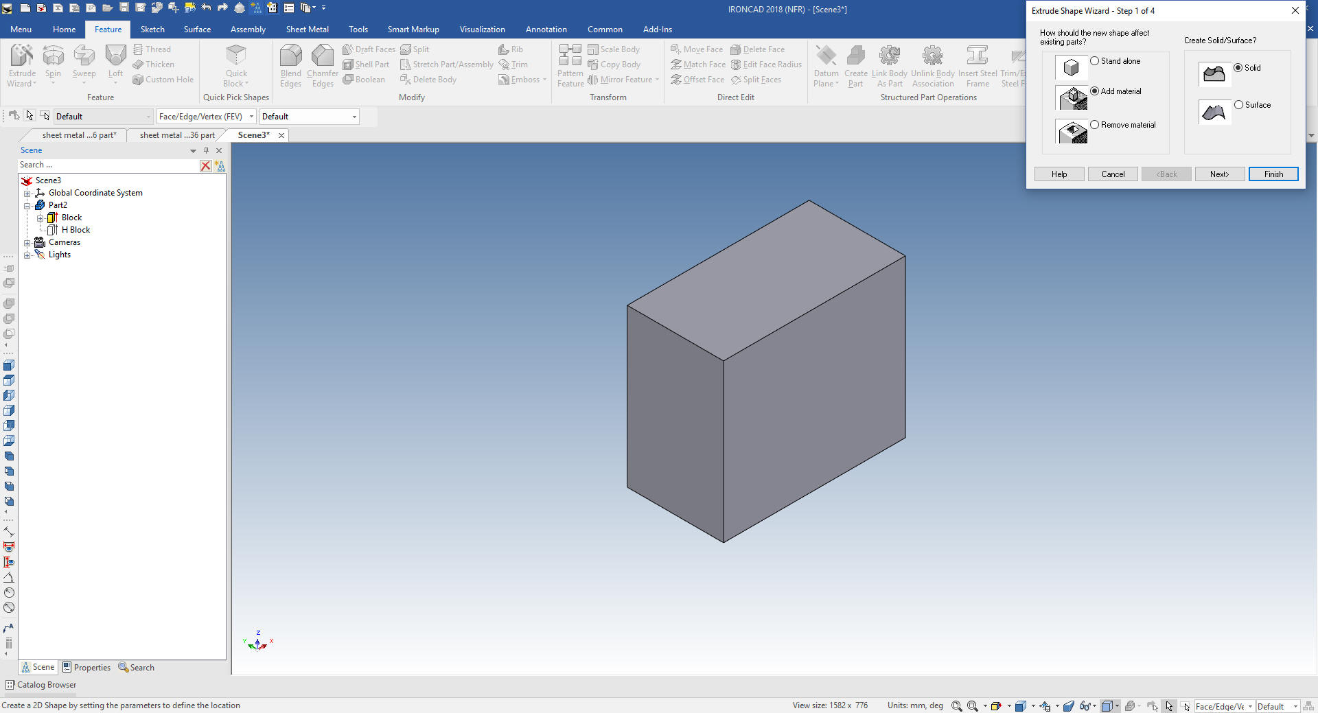
First we initiate
the Extrude Wizard and select remove material.
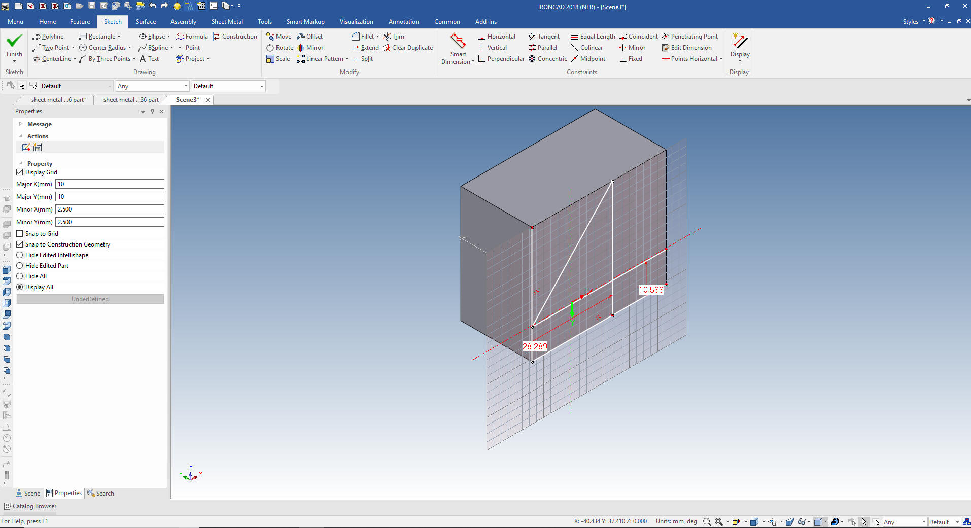
Now select the front face. I just projected the front and bottom
edge and offset the lines to locate the end of the diagonal line.
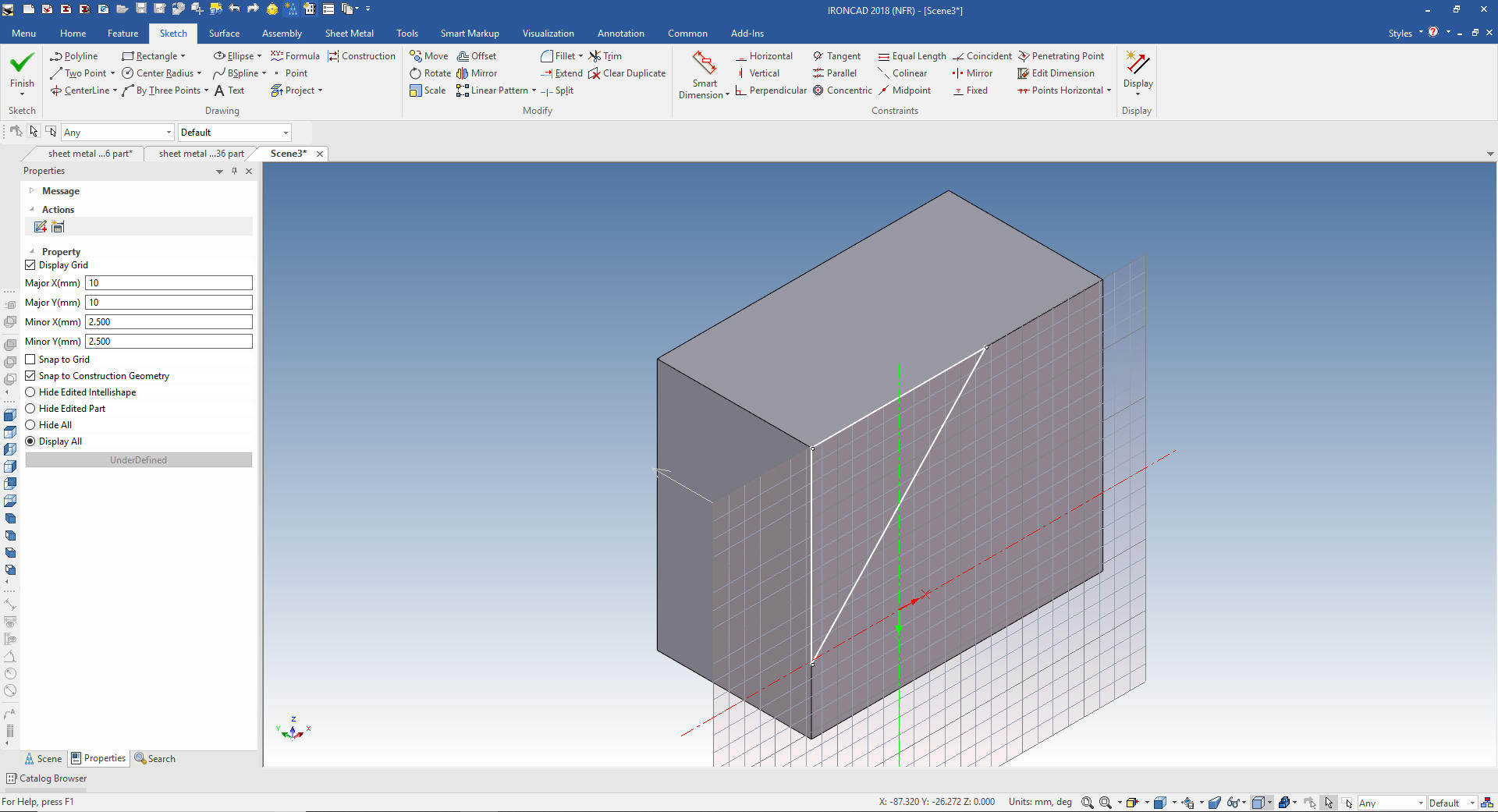
We
trim and delete the construction graphics. Notice no constraints.
We
select finish. You can see drag and drop is a much more productive
method.
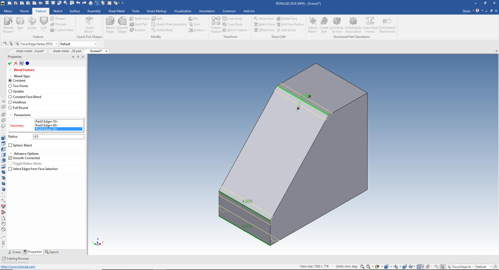
Now we
will add the BR of 2.5mm and the material thickness and at the 4.5
blend
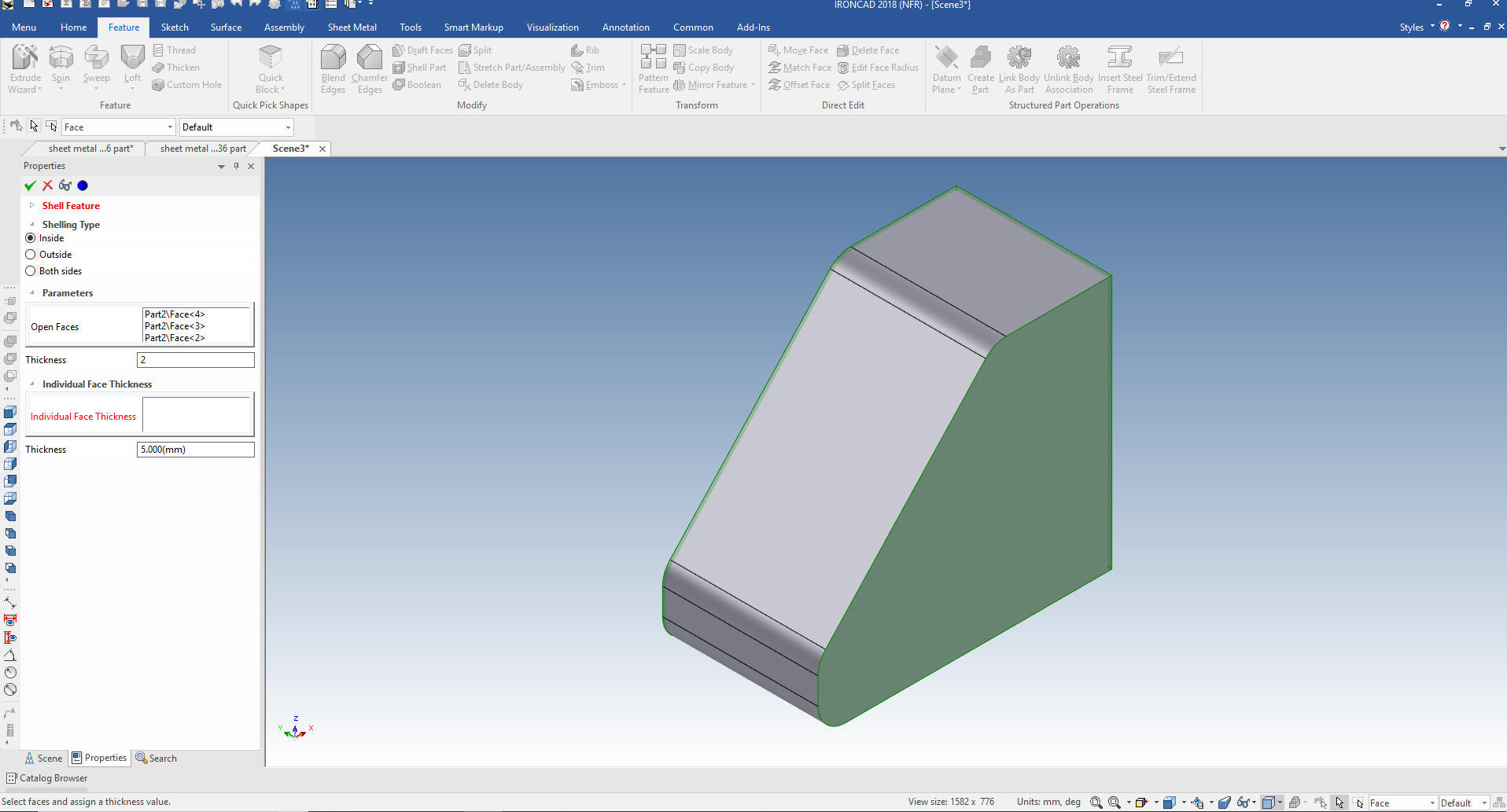
We can now shell the part. I could sketch the cut but this is so
much faster. Shelling is a big part of sheet metal modeling. I
select the three open faces and set the shell to 2mm. When you
design sheet metal you are working on overall shape that may be difficult to create with the sheet metal program. I just
want to make you all aware that it can be done a different way.
We
drop a hole block to trim the bottom. IronCAD operates much
differently than the Solidworks clones. It is fun and as you get
proficient there many more flexible options.
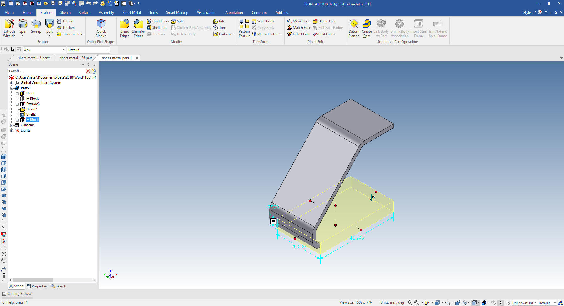
Now we
can added the the bottom shape and other features as we did above.
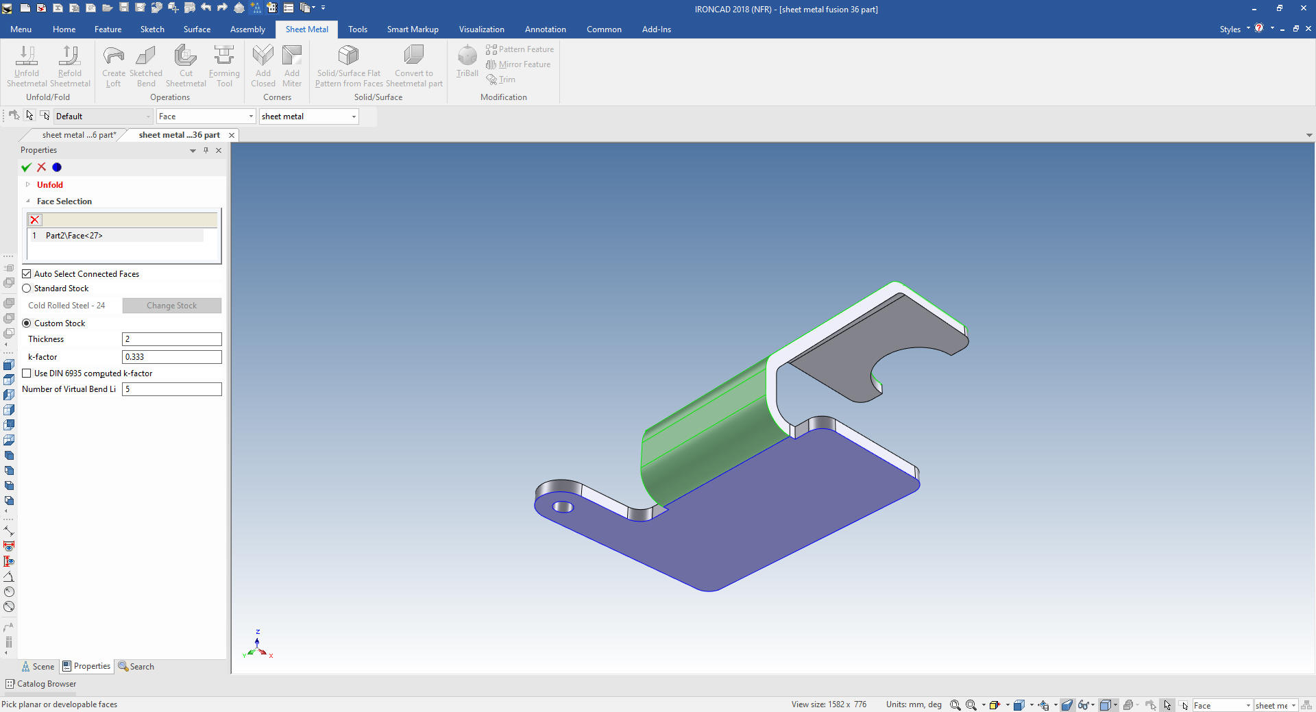
Unless you are working in a sheet metal house you should send the
AID (drawing) and the 3D model to the sheet metal supplier to create the flat
pattern. But IronCAD will unfold any correctly designed model.
We select the base face.
The unfolded flat pattern
So there you go. That is how we
modeled sheet metal parts in the past and I still do.
It is
very important that you look into how you or your engineers are
creating the parts. Streamline Sketching and Feature Based Modeling
is easy to learn and implement. It, alone, will increase
productivity 10X. Now, IronCAD with its unique integrated
history/direct edit functionality can increase your productivity
another 5X or more with changes! Again, time is money in
engineering.
More on Streamline Sketching and Feature
Based Modeling.
To experience this increased level of productivity, please download
IronCAD for a 30 day evaluation. Legacy data is no problem, IronCAD
can read the native files of all of the popular programs. IronCAD is
a great replacement for the subscription only Autodesk and PTC
products.
Give me a call if you have any
questions. I can set up a skype or gotomeeting to show this part
or answer any of your questions on the operation of IronCAD. It
truly is the very best conceptual 3D CAD system.