|
CORE/CAVITY SPLITs IN 5 MINUTES II! ZW2020 Mold Design! So Simple a Draftsman Can Do It! See Core/Cavity Split in 5 Minutes!! 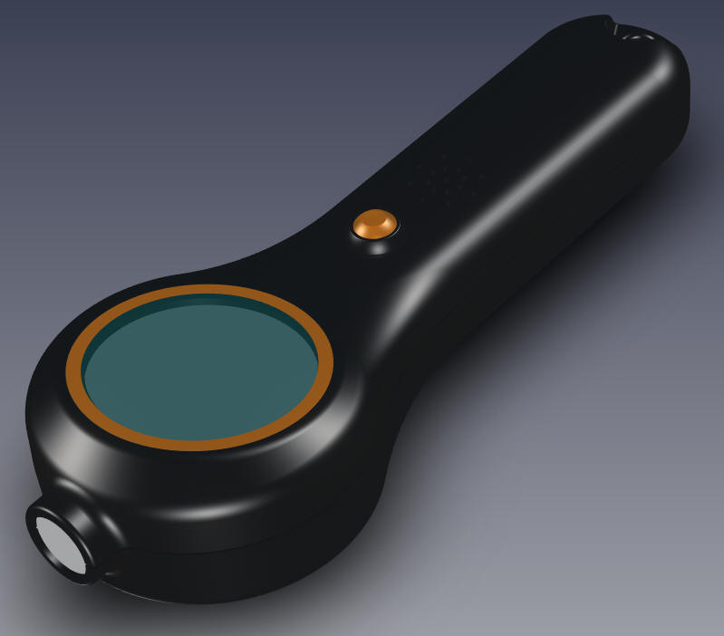 |
|
I first did this exercise in ZW3D 2018. I have my beta of ZW3D 2020 and it is much better and faster. With a straight pull it is just a couple of steps. It was easy before but it is now virtually 123!! 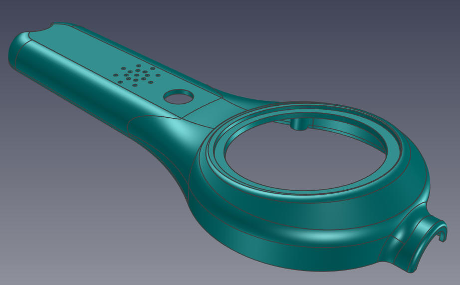 Larry and Charlie of Prototek finalized the design and now we are preparing to get a quotes on the molds. I had to make the prototype into a functional part. I designed the part with all the draft and basically ready for prime time to assure no surprises. But many of the features that make it a good mold have to be added. 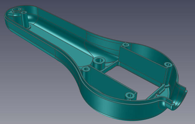 As a single designer I do not have the luxury of a checker so it is up to me to make sure the parts are correct for molding, assuring there are no unintentional vertical faces or under cuts. The design was done in IronCAD and I am very lucking to have ZW3D Mold Design available to check the parts. 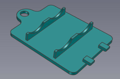 I export the models as STEP or Parasolid to ZW3d. I have found that Parasolid is a very good translation format. IronCAD has both the ASIC and Parasolid kernel so it does a good job with both formats. I did find out that the Mold Designers used Solidworks and provide both STEP and Parasolids since Solidworks uses the Parasolid Kernel. Take a look at my first article on this subject. It gives a bit more information on my introduction to plastic part design. I was probably the first designer to jump engineering disciplines due to my 3D CAD experience in 1983. Core/Cavity Split in 5 Minutes!! 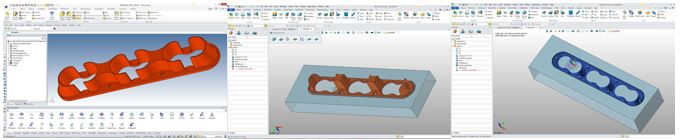 Here is the Hand Held Linefinder. 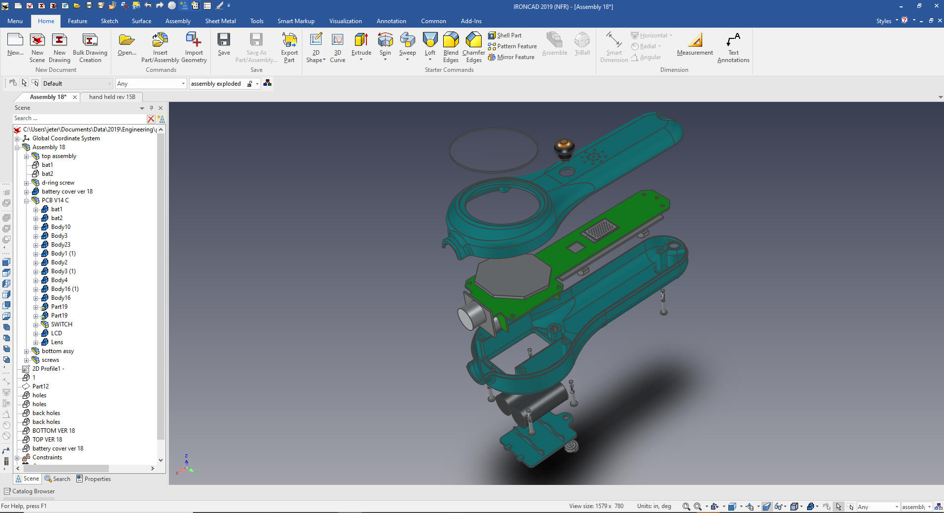 We will start with the Top. We export the model as a parasolid out of IronCAD and import it into a new ZW3D part file. 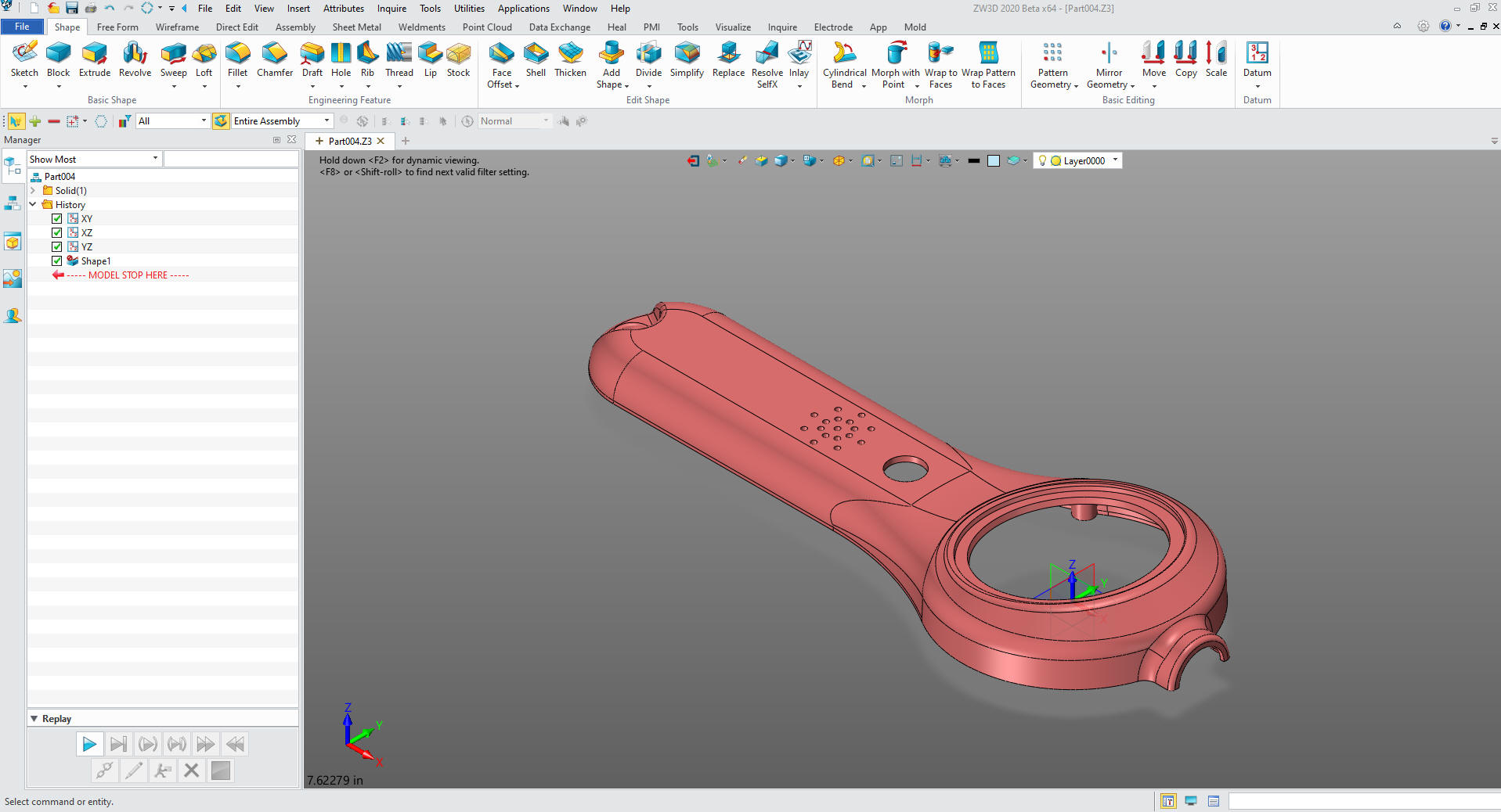 We go to the mold menu and select "Region Analysis" and select "Calculate" to set up the core and cavity. I will give us a report on the model, whether there are unexpected vertical or undercut faces or other problems. You can see I have no problems with this model. 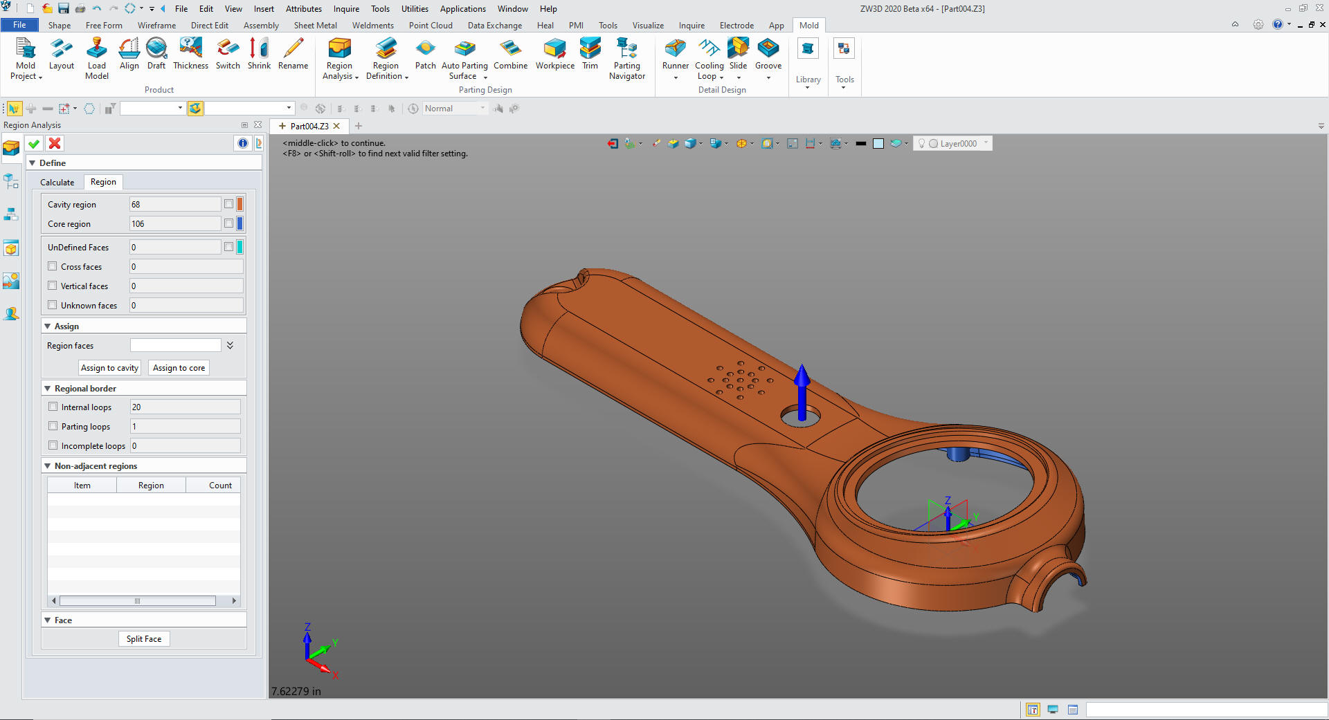 We now use the "Region Definition" to define the core and cavity and parting lines. 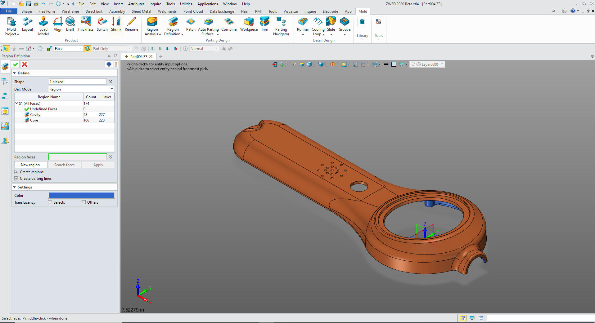 We now select patch and it finds all of the pass throughs. One step. 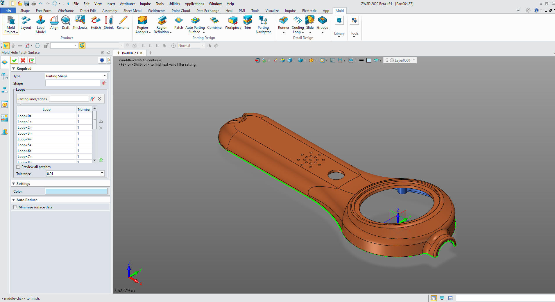 Now we select the "Auto Parting Surface" 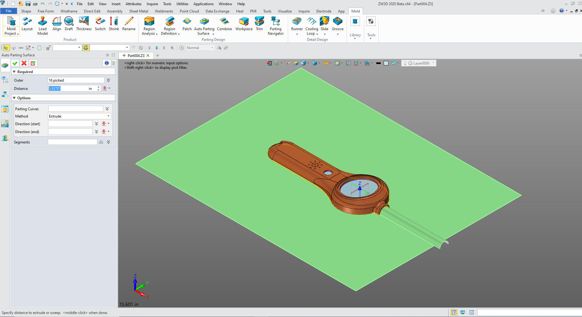 We now create our work piece and locate it. 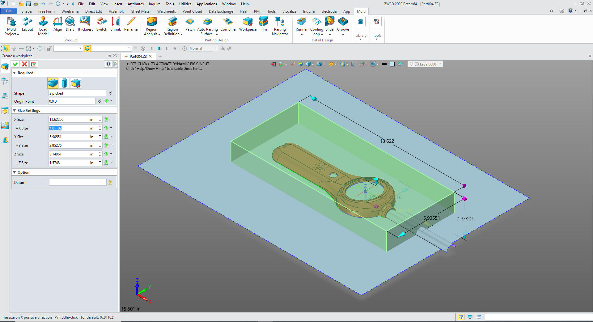 Then we trim the mold. 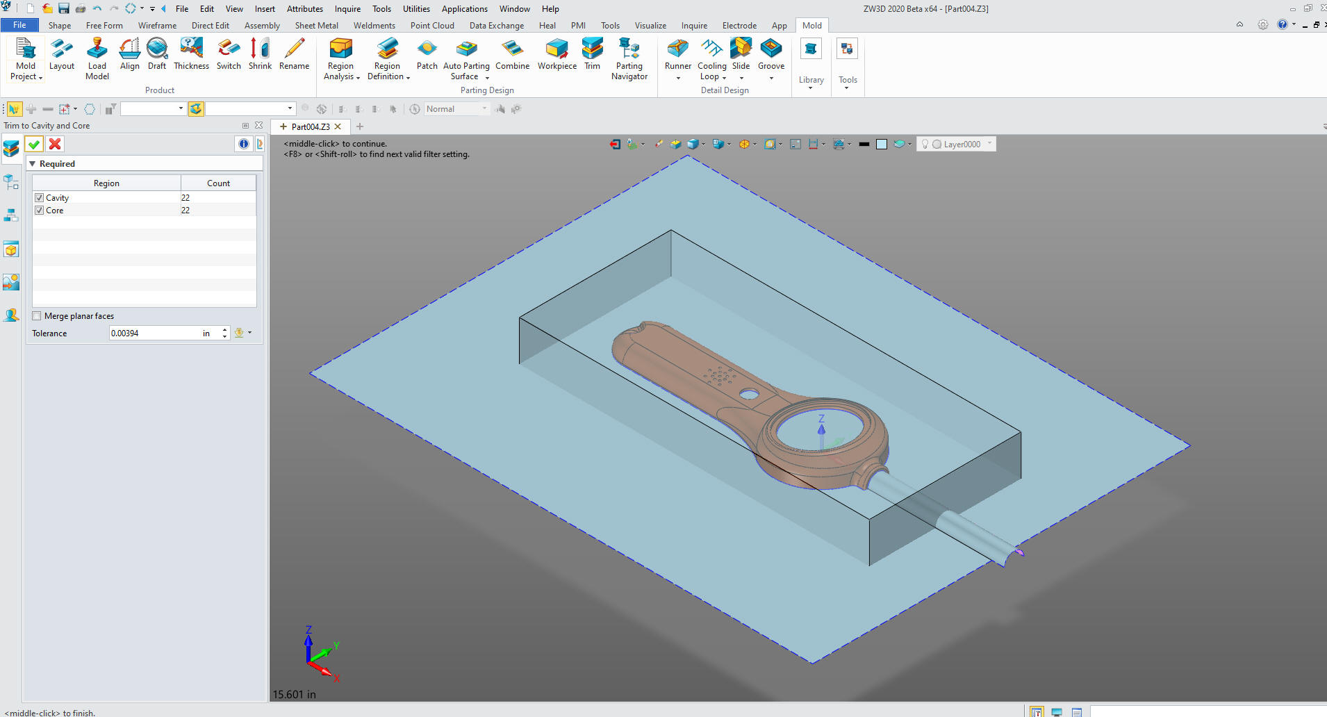 We have our two molds 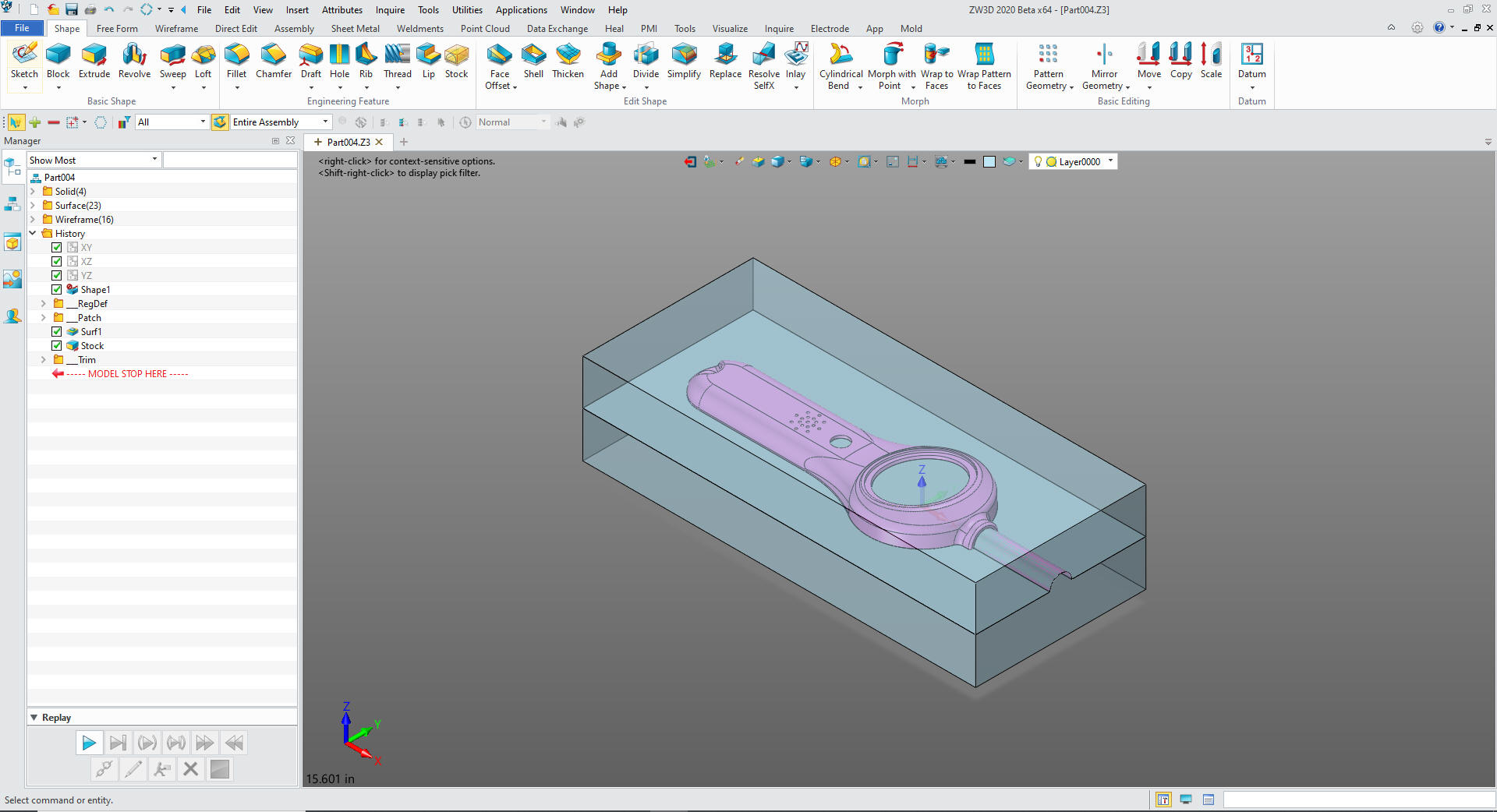 Then my favorite part. Viewing the molds. 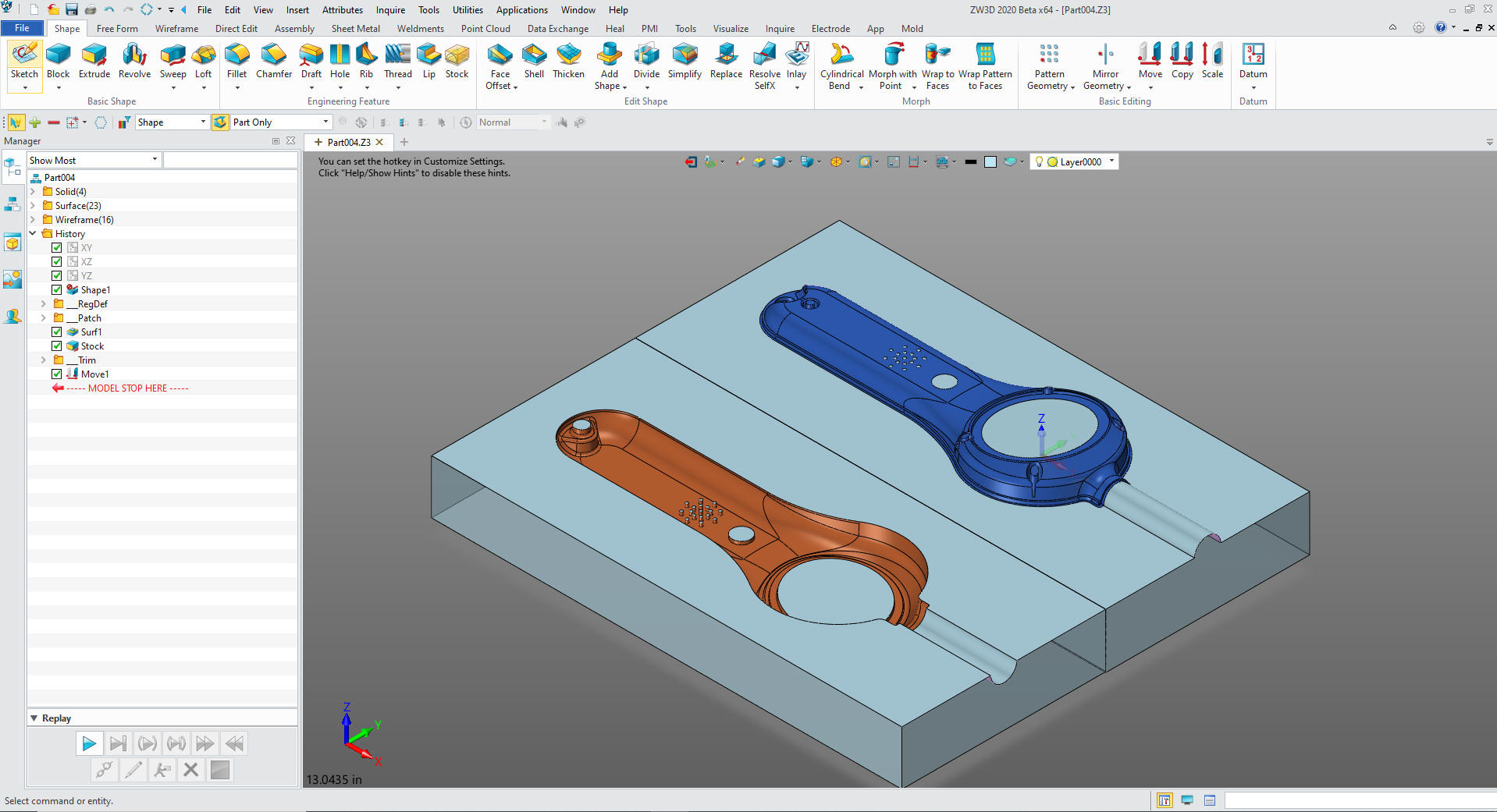 The Bottom 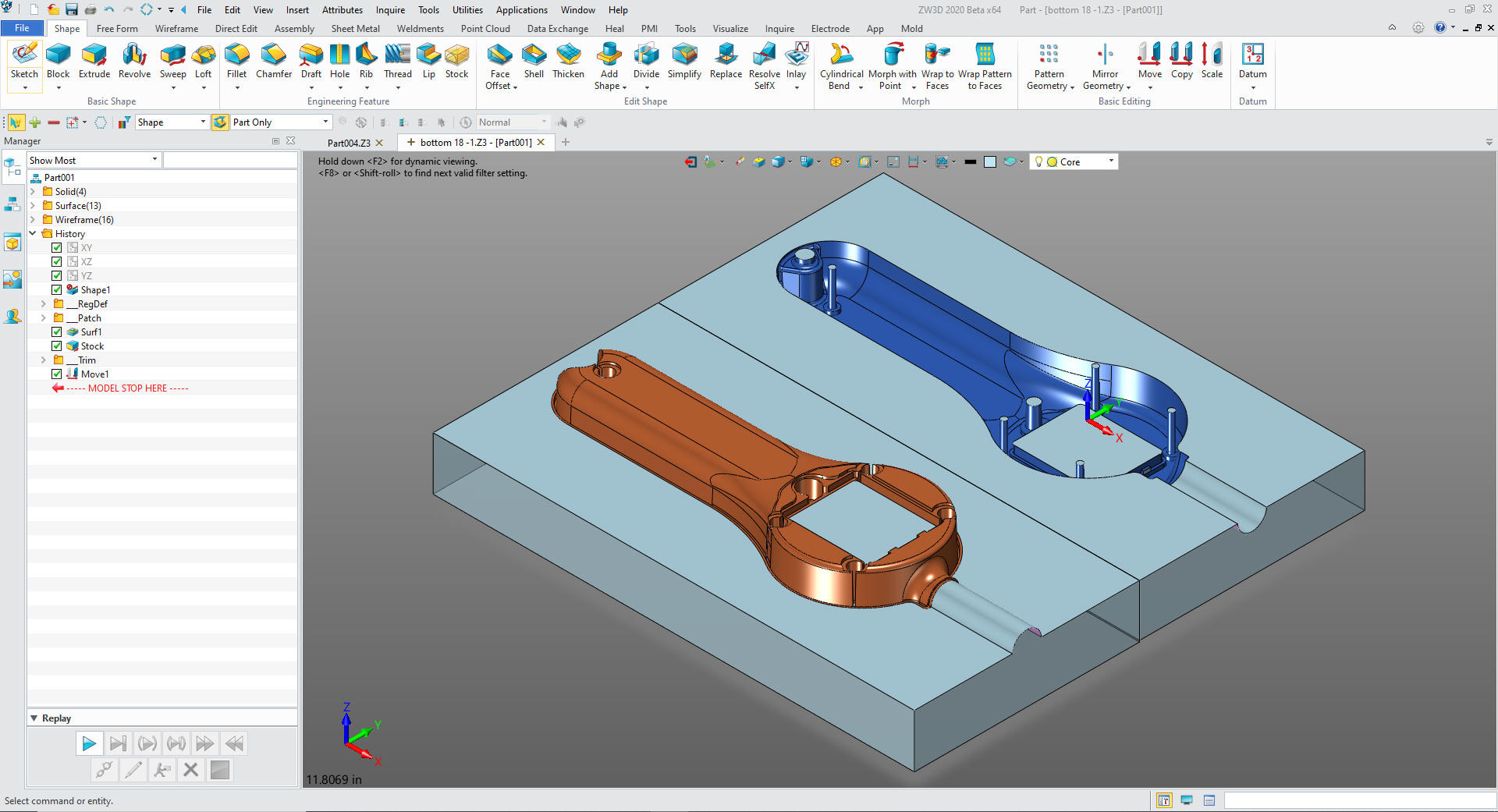 The Battery Cover 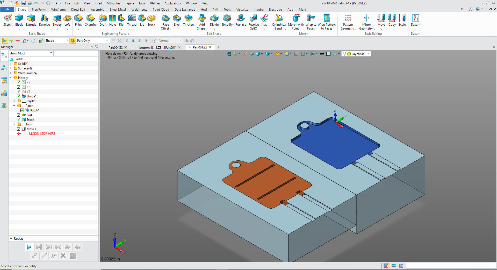 So you can see it is as easy as one, two, three! Nothing like a good core/cavity split to realize when you are designing plastic parts you are actually designing holes in space! Give it a try. No matter what system you have you can bring your parts into ZW3D. No need to export in a neutral format, ZW3D reads the native files from all the popular programs including PMI For more information or to download ZW3D Besides integrated mold design, ZW3D Pro includes all of ZW3D Standard functionality such as History Based/Direct Edit Solid modeling, Easy Multi-Object Design (Top Down), integrated drawings, Free Form Class A surfacing, Robust Reverse Engineering including complete wireframe design and much more. ZW3D is a true integrated CAD/CAM system, you can go from Mold Design to CNC programing and machining.
TECH-NET Engineering Services!
If you are interested in adding professional hybrid modeling capabilities or looking for a new solution to increase your productivity, take some time to download a fully functional 30 day evaluation and play with these packages. Feel free to give me a call if you have any questions or would like an on-line presentation. Joe Brouwer 206-842-0360 |
TECH-NET ASSOCIATES | RENDERING OF THE MONTH | CAD•CAM SERVICES
HARDWARE | TECH TIPS | EMPLOYMENT | CONTACT