|
CORE/CAVITY SPLIT IN 5 MINUTES! | |
 In 1982 I was introduced to 3D Computervision CADDS 4 while on contract with Williams International in Walled Lake, MI (Fondly called Willie's Rocket Shop). I quickly became an expert. The 1980's - 3D CAD - The Beginning I took a contract with Comdial in Charlottesville, VA in 1983. I was hired only because of my 3D CADDS 4 experience. I was probably one of the first designers to jump engineering disciplines, in this case, from aerospace to plastic product design only because of my 3D CAD experience. Being an aerospace designer, plastic product design was a new world. It is basically all graphic design. My work was on new telephones.  I
would walk through the manufacturing area and talk to the mold makers and
machinists. Review the different pieces as they came out of the mold. One
part was quite interesting. If you remember the old hand set, it was not a
straight forward design. When the part came out of the mold the worker would
have to shake it to get the two cores that made the hole between the
receiver and transmitter out. It was quite intriguing. I
would walk through the manufacturing area and talk to the mold makers and
machinists. Review the different pieces as they came out of the mold. One
part was quite interesting. If you remember the old hand set, it was not a
straight forward design. When the part came out of the mold the worker would
have to shake it to get the two cores that made the hole between the
receiver and transmitter out. It was quite intriguing.
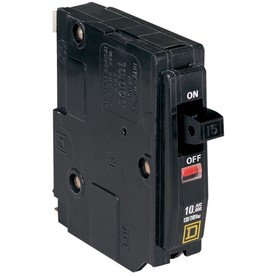 Now with a bit of plastic design experience under my belt and my CADDS 4 experience I took a job with Square D, Lincoln, NE in 1987 to design circuit breakers. I learned much more about plastic product design. 3D CAD/CAM was well in place and there were now CNC programmers you could work with. They sat next to us and informed us of the design process from their point of view, in not so pleasant terms. Prior to this we just designed the parts with no draft. Draft was very difficult in 3D wireframe. We defined the draft on the AID (Associated Information Document (drawing)) in a print format which was the only manufacturing deliverable pre CNC. But now we would give them the 3D wireframe in the form of an 3D IGES file which they would use 2.5 axis machining. Circuit breakers are very simple. I founded TECH-NET, Inc in 1987 and became a Dealer of PC based 3D Cadkey. I ended up back home in Seattle selling PC based 3D CADKEY to Boeing and all their suppliers, plus most of the manufacturing companies in the Great Northwest. The 1990's - 3D CAD/CAM Moves to the PC!! I provided 3D CAD sales, training, support and engineering services. One of my customers was SpaceLabs. In the beginning of 3D CAD we designed in 3D wireframe. They came to me to add draft and net surfacing to one of their wireframed designed parts. Stereolithography was just being introduced and they wanted to get a .stl. I quoted 55 hours. They howled "It didn't take that long to design!" I said, "Well, you should have designed in the draft." It was funny they gave me a similar wireframe part later after we had solids. It took 15 hours. With the introduction of solids, draft quickly became part of our design process. 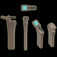 The first
plastic product I designed was the Prototek LineFinder in 1998. The first
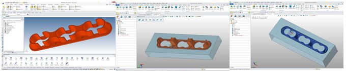
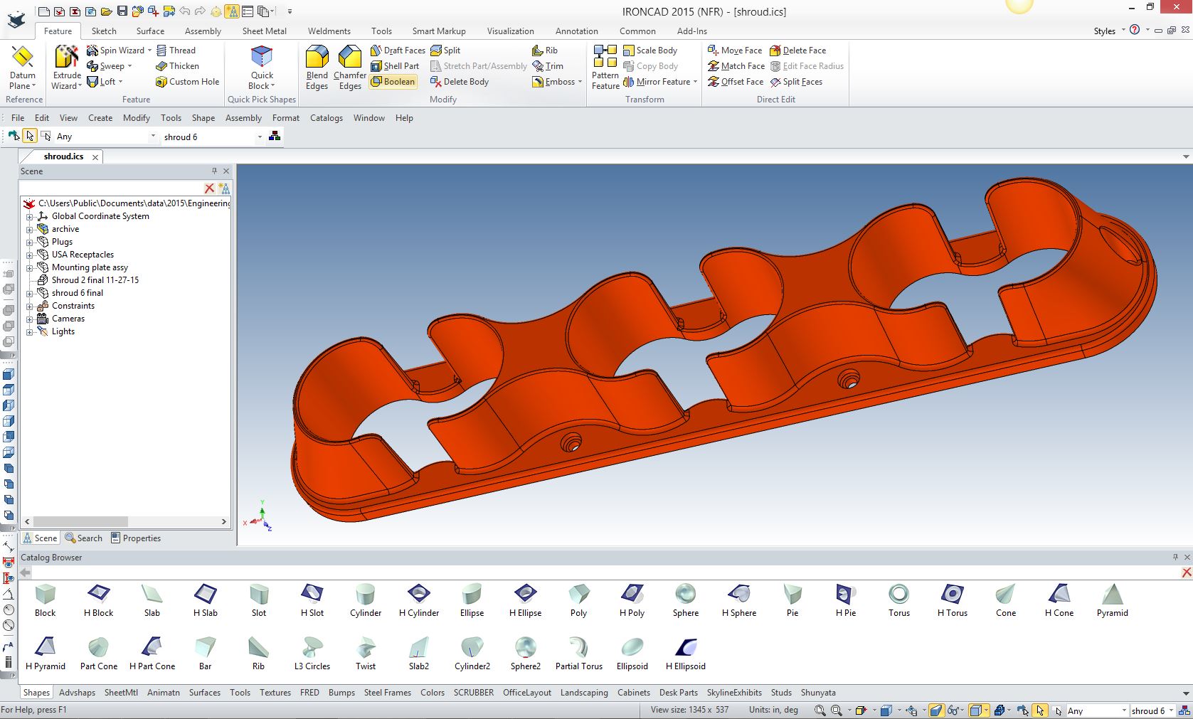
plastic product I designed was the Prototek LineFinder in 1998.It was an interesting experience and a great story. It was designed in IronCAD and it describes the first of the 3D .stl printing to create silicon molds. Then was modified for injection molding providing 3D IGES files to produce the molds with Pro/e CNC. The Prototek LineFinder I started doing quite a bit plastic product design from that point on. I would struggle to create the core/cavity split to make sure the parts had the correct draft and the parts could be made. Early on, CADKEY could create silhouette curves to define the parting line, then you would explode the solid model and separate the faces pass through's were a pain. Later CADKEY had a core/cav split function that would separate the faces. I was a bit funky and still took a lot of work. We took on ZW3D and it had an integrate mold design package. I really never got into the mold design side until I was contacted by one of my ZW3D mold maker customers that was struggling with a complex part trying to create the core/cavity split. He actually had ZW3D mold but was only using the CNC portion of ZW3D since he had a copy of Cadkey he was familiar with. Cadkey just couldn't do the job. I can't show it here but it was a doozy!!! We were really having a hard time and I said let's send it to ZW3D support. The next day we had the core/cavity split. We reviewed the process and saw some errors in the design that CADKEY overlooked. It was designed in Solidworks and the designer made some amateur plastic product design mistakes. Even though they were small mistakes, they stood out like a sore thumb after running it through the core/cavity split process. We just made a few changes that would not alter the function or aesthetics of the part, but made the core/cavity split much easier to create. I studied the process and saw it was very simple. So I started checking my parts. ZW3D mold would quickly show any problems with the part. Like faces that did not have draft. I got quite good at it. Not that it is a complex process. But it was fun to bring the parts in and assure they were complete and correct. Here is a picture of the shroud and a few other parts I designed. 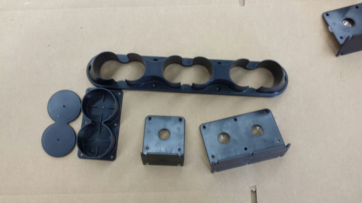 I will show you this simple process. Here is the original shroud that was done in IronCAD.
I export it as a parasolid .x_t file to ZW3D. 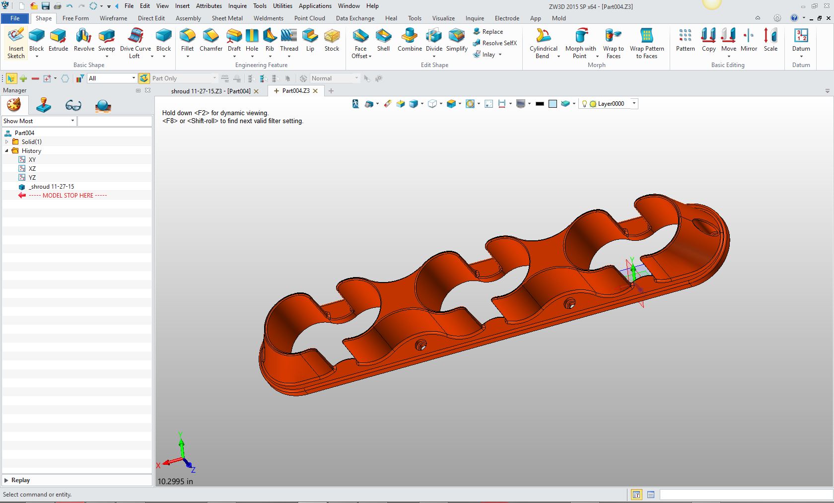 Setting it up in the top View makes it a bit easier to process. If it didn't I would rotate it into the top view. 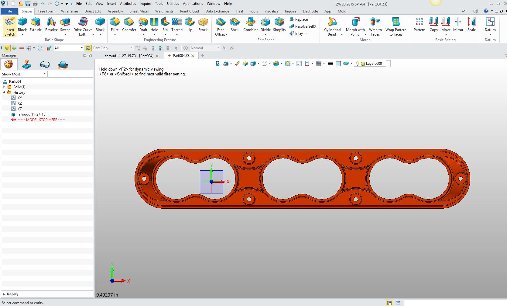 Now we go to the mold design menu and select Core/Cavity region definition! You can see it has recognized 380 undefined faces. 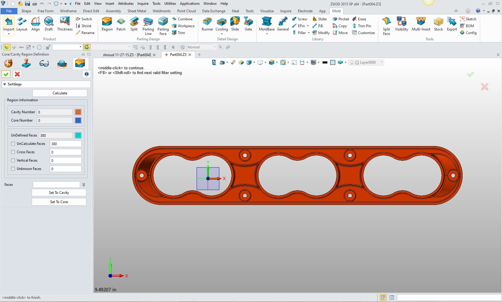 You can see that the core and the cavity faces are now defined and there are no errors. 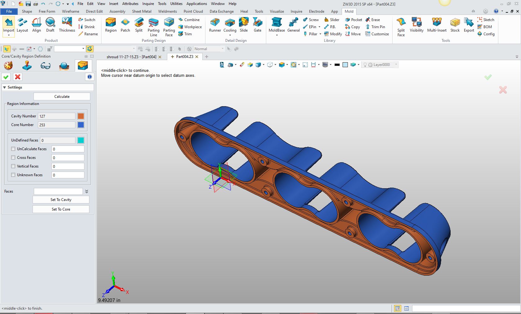 We now split the core/cavity. 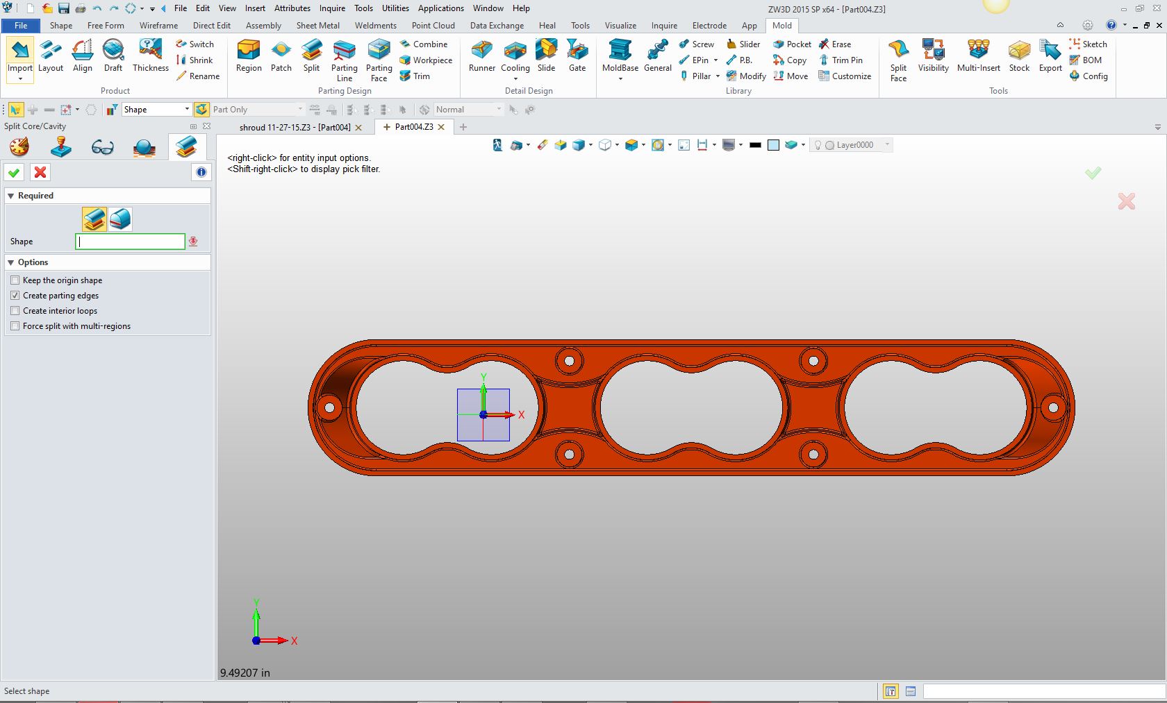 When you select go it comes up with this notice that the 2 regions have been defined. 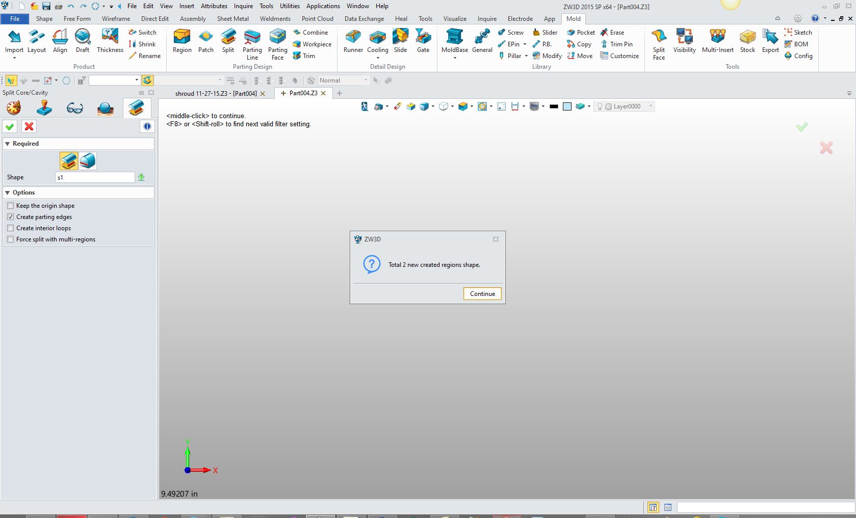 Now we create the parting face 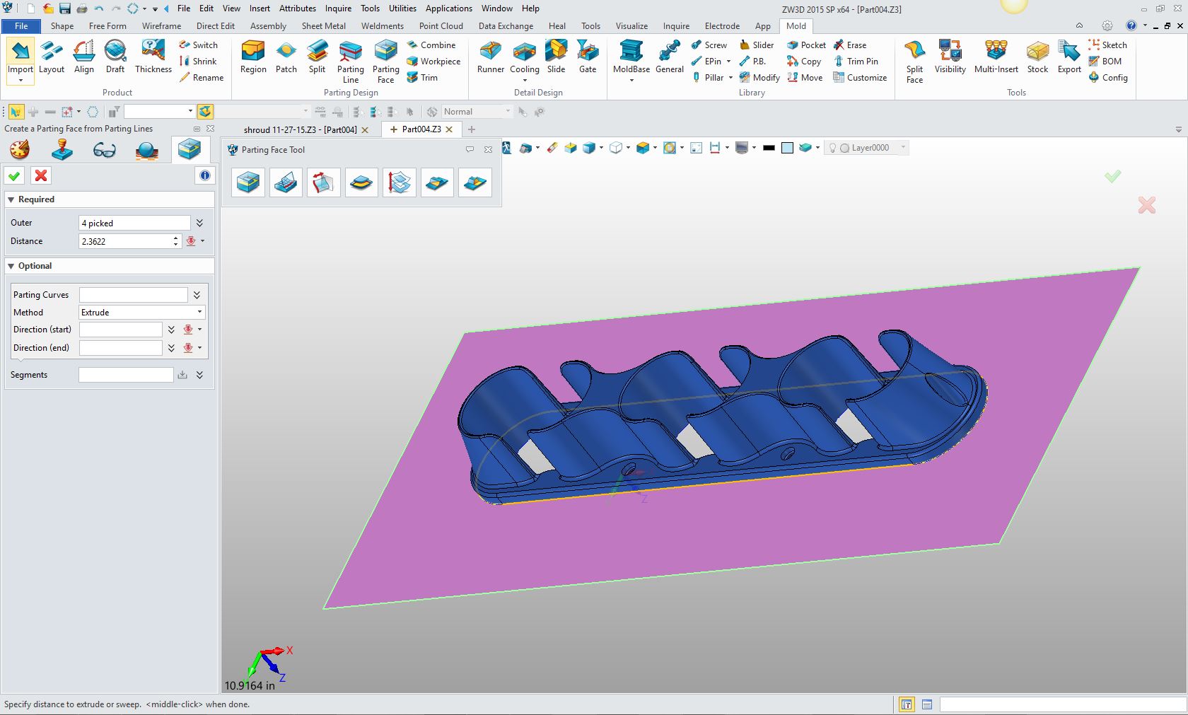 We then create the work piece and size it correctly. I am not too worried about the size just that it fits inside the parting face. If you were to continue to create the mold I am sure you would put a bit more time into it. Please realize this is a fully integrated mold design package. Watch the following video is shows some of the steps we had to go through working with the Solidworks model above then continues to full mold design. ZW3D Mold Design 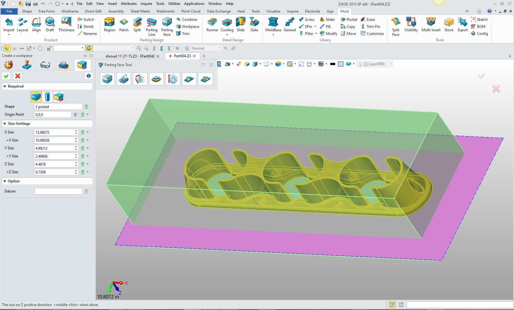 Now we are ready to trim the mold plate to core/cavity by parting faces. 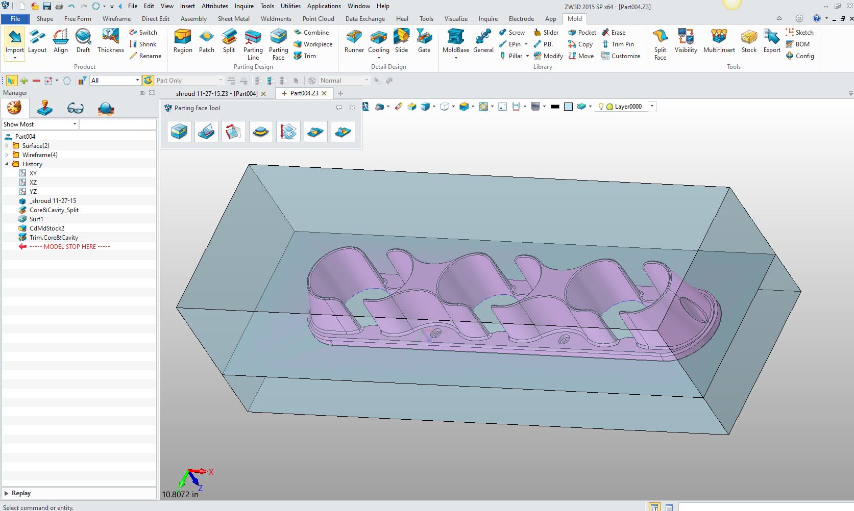 Job done in a few easy steps. I get a big kick out of seeing the resulting core and cavity created by my design. Here is the core 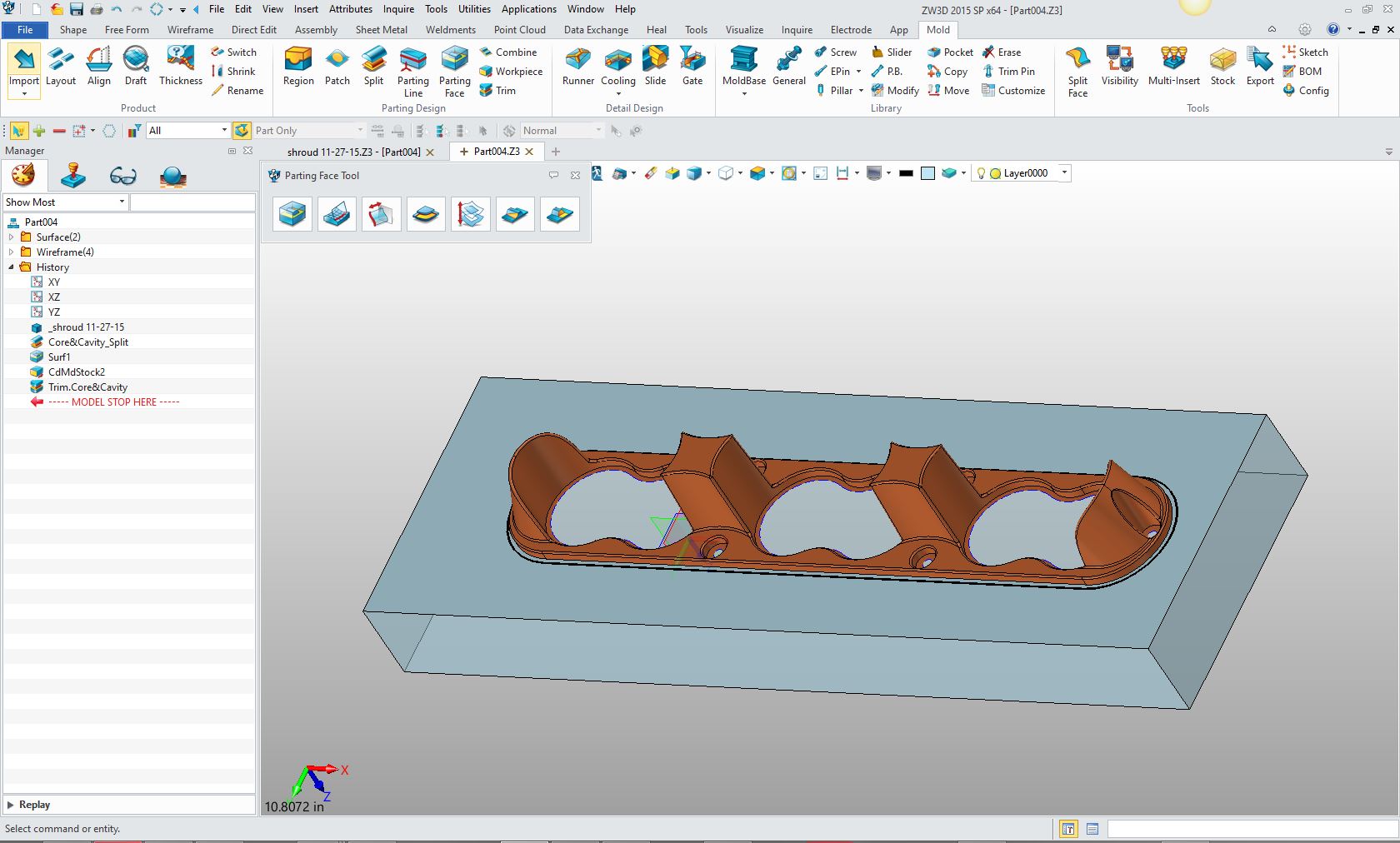 and cavity 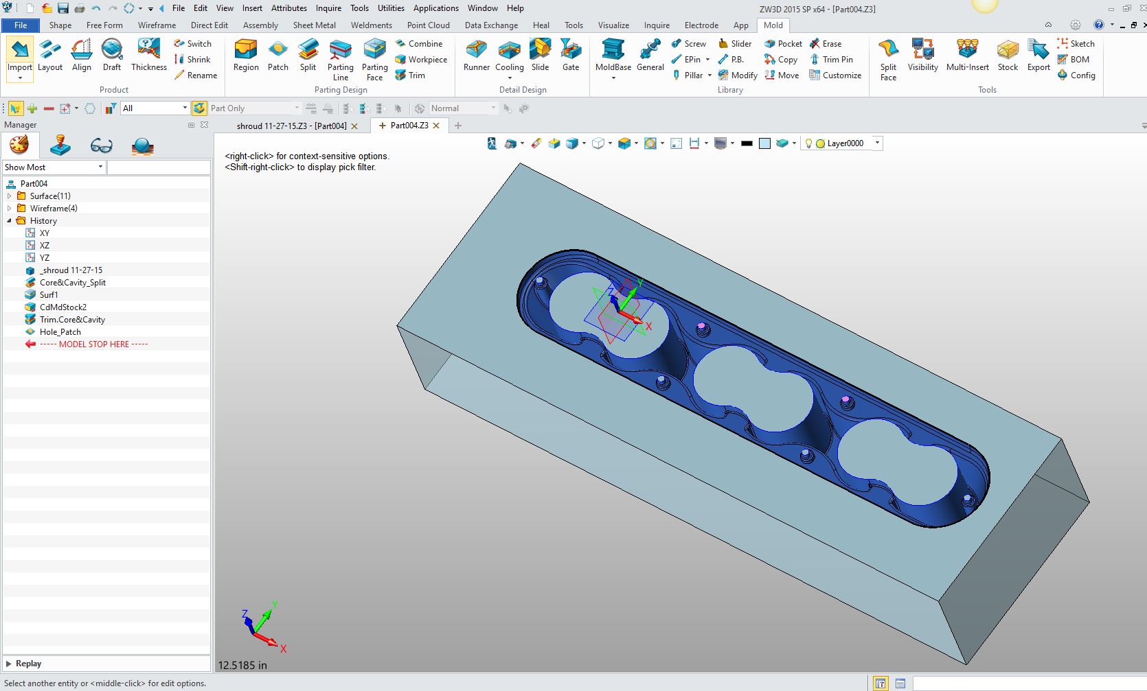 So you can see it is as easy as one, two, three! Nothing like a good core/cavity split to realize when you are designing plastic parts you are actually designing holes in space! Give it a try. No matter what system you have you can bring your parts into ZW3D. No need to export in a neutral format, ZW3D reads the native files from all the popular programs including PMI For more information or to download ZW3D Besides integrated mold design, ZW3D Pro includes all of ZW3D Standard functionality such as History Based/Direct Edit Solid modeling, Easy Multi-Object Design (Top Down), integrated drawings, Free Form Class A surfacing, Robust Reverse Engineering including complete wireframe design and much more. ZW3D is a true integrated CAD/CAM system, you can go from Mold Design to CNC programing and machining.
TECH-NET Engineering Services!
If you are interested in adding professional hybrid modeling capabilities or looking for a new solution to increase your productivity, take some time to download a fully functional 30 day evaluation and play with these packages. Feel free to give me a call if you have any questions or would like an on-line presentation. Joe Brouwer 206-842-0360 |
TECH-NET ASSOCIATES | RENDERING OF THE MONTH | CAD•CAM SERVICES
HARDWARE | TECH TIPS | EMPLOYMENT | CONTACT