Feature Based Modeling!
Streamlined Sketching!
Defined!
|
The History of Sketching When I was introduced to 3D Computervision CADDS 4 in 1982 it was 3D wireframe while on contract with Williams International in Walled Lake, MI. It had a mini-mainframe computer in a refrigerated room, a Versatec 34 inch roll plotter, an admin room with a control terminal, removable hard drive and a tape back up system. Are you ready for the price? $250,000 per seat with a minimum purchase of three. The 19 inch monitors were monochrome: Green on Black. You could have highlighted green to help distinguish a bit. Look at the lower image, are you look up or down at the part? Yes, that was a constant problem. Especially when working with the poor engineers. It was really in 3D!!
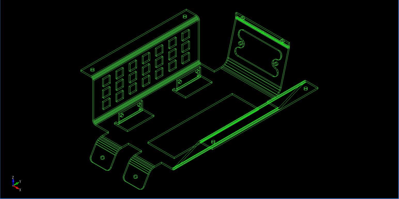
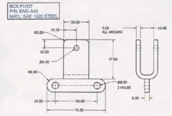
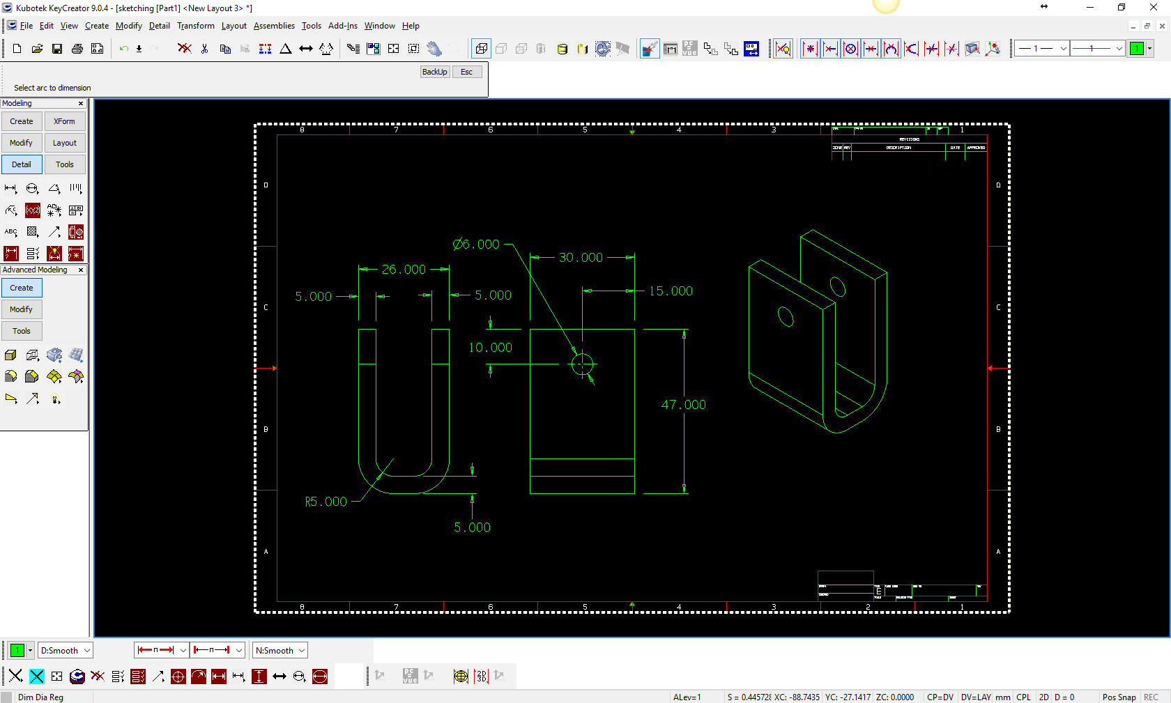
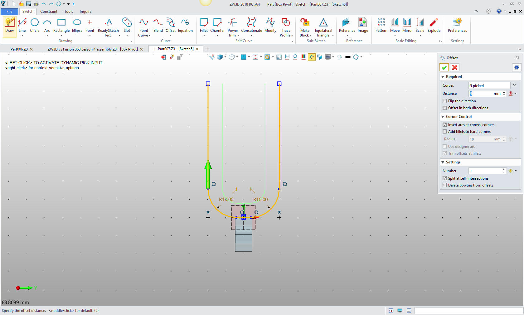
I quickly became an expert and probably was the first to get a job due only to my CADDS 4 experience. My rate went from $20.00 to $35.00 per hour! With loads of overtime I was soon rolling in dough. I took a contract at Boeing in 747 Flight Deck in 1986 as a manual board draftsman just to get home to my young family. I was a "3D CAD designer". Boeing had just switched to Catia 2. It also was a 3D wireframe system. Only the direct prima dona draftsmen got on the system. No hope to get on CAD there. I was whining about not being on CAD and a fellow said there was a PC based 3D CAD system on a couple of Compaqs. I took a look and it was PC based CADKEY. It was incredibly similar to CADDS 4 and I was up and running in 2 weeks of lunch hours. I convinced the boss to allow me to do a project, the first observers workstation. It was such a success that they started buying CADKEY by the dozen. I was the main trainer. I purchased CADKEY, a 286 Compaq and a 19 inch CRT for $8500.00. But at $20.00 per hour my job at Boeing was short lived. They offered me a dollar to stay, I laughed and headed out to Square D, in Lincoln NE for $35.00. I founded TECH-NET and made my first sale for 3 seats of CADKEY to Square D, the rest is history. The 1980's - 3D CAD - The Beginning I continued to sell CADKEY for another 22 years. They went direct and got rid of the dealers in 2009. But I had quit using it as my main design system moving to IronCAD in 1998. CADKEY was rereleased as KeyCreator in 2003, basically duplicating CADKEY with a bit different UE. It still was a dumb system, but was a fairly good highbred modeler, with a mixture of 2D/3D wireframe, surfacing and Boolean solids. I replaced it with ZW3D which is a much more robust hybrid modeling system. With that under out belt let's get to the subject. Why do we call them Sketches? All CAD operators in the beginning were draftsman and brought our drawing practices to 3D CAD. We would draw like you did on the board with sliding triangles. Mostly vertical and horizontal parallel lines offset. We would add the lines and arcs to complete the 2D graphics. We did not use the term "sketch" at the time. We called it "2D graphics" and was made up of lines, arcs and splines. Can anyone tell me why they called them "Splines"? We could extrude and revolve only. The program would create the graphics by joining the graphics together. I will show you with the original concept in KeyCreator 2009. Yes, it still has this capability. I had to do a refresher course on how to do it. As we moved to Solids, CADKEY offered a solidify function that would turn wireframe to solids. We just had to make sure there were no spherical fillets. I have set up KeyCreator as CADKEY was in 1986. Black background, I will set the color to green, even though CADKEY had 16 colors, to emulate the even more convoluted CADDS 4 experience. Color did finally show up on CADDS 4X around 1984 at a $25,000 option. We would fight for the colored station. Welcome to living history! LOL Actually I could bring up CADKEY, last released in 1998 and can still load on Windows 10, but it really isn't much different than KeyCreator which I am used to. We are going to create the "U" shaped channel. I will be using this channel later to show a variety of modeling techniques as compared to "Constrained Sketching". Inside fillet is 5mm.
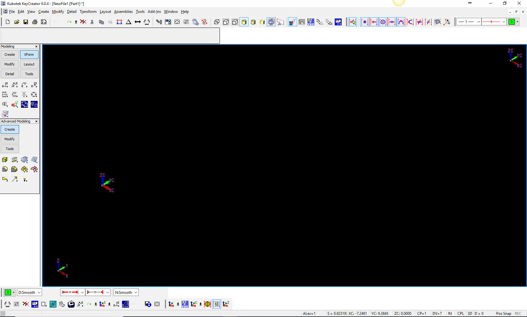
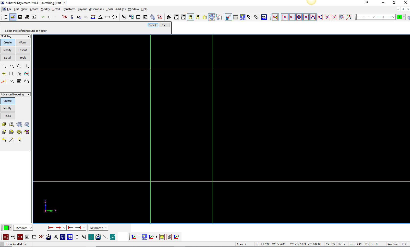
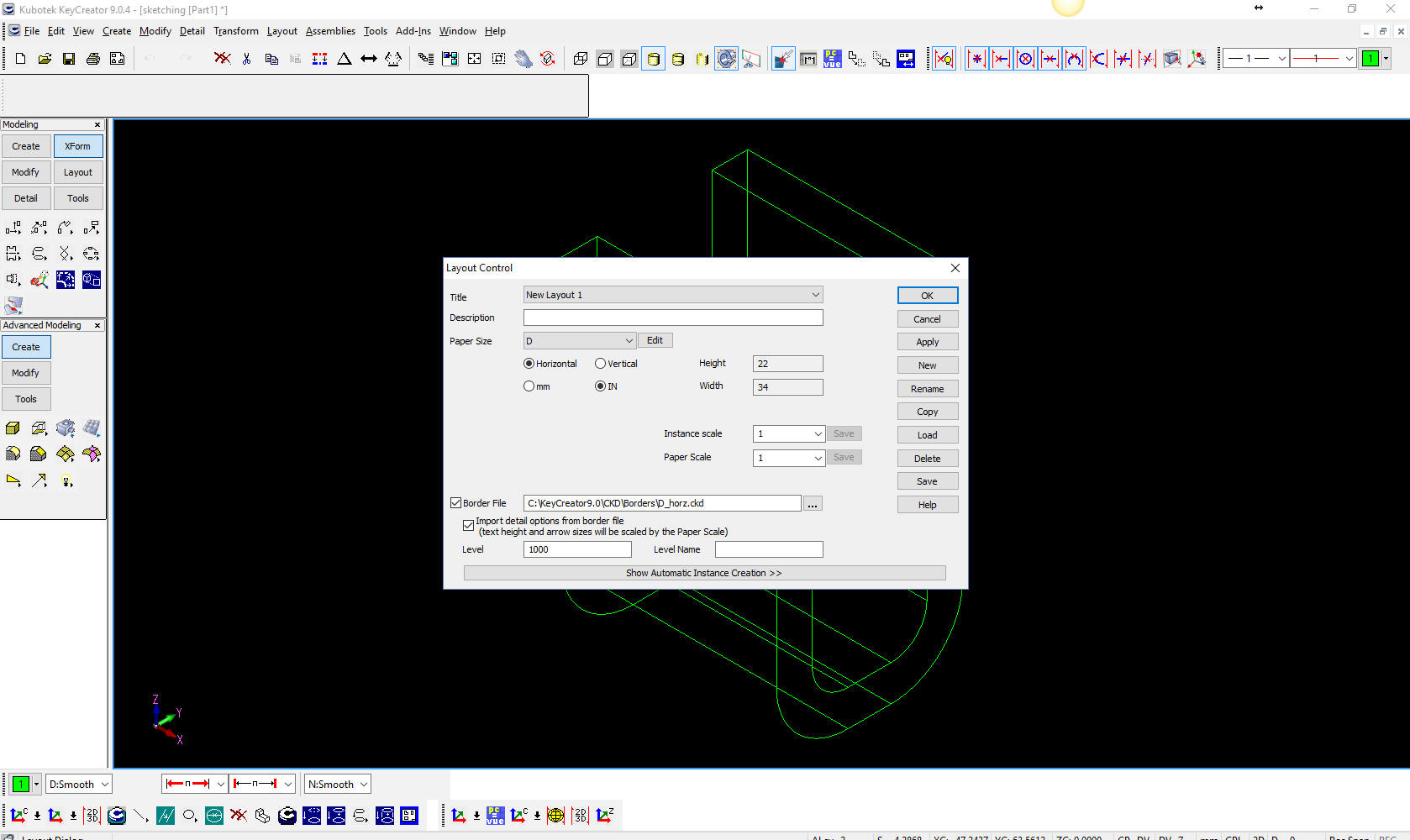
We open KeyCreator and it comes up with a new file we will set the units to mm.
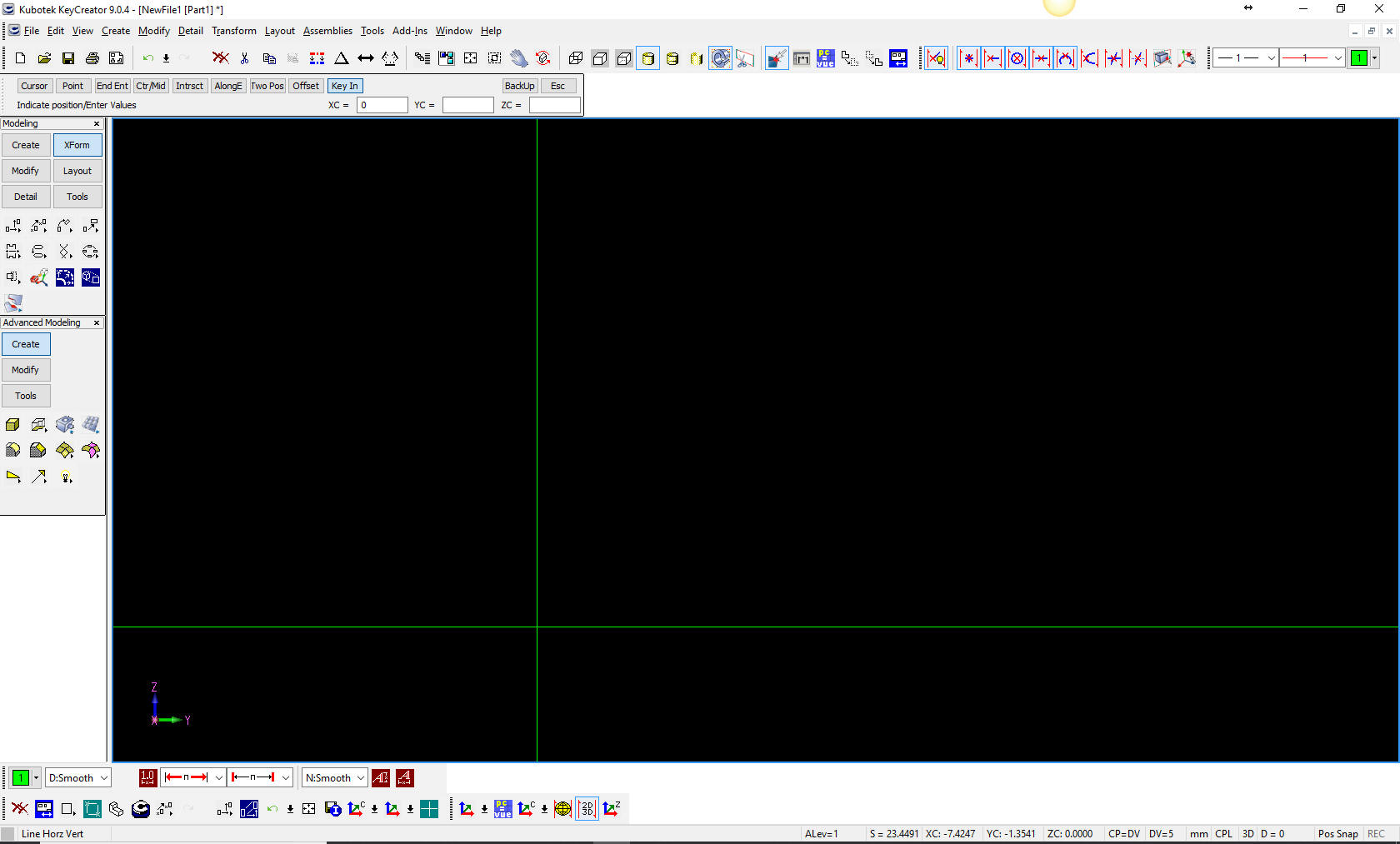
We will switch to view 5 or right view and create a horizontal/vertical line at X0Y0Z0. No there are no separate planes, they are implied in a flexible Cartesian work space.
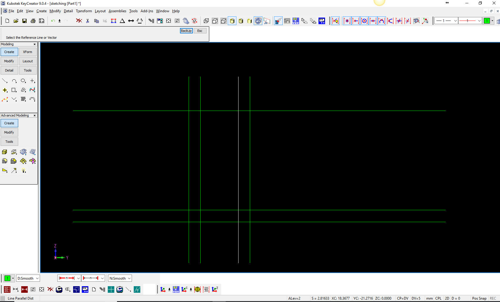
Now we will create the basic rectangle with parallel lines.
Now we will create the 5 mm walls.
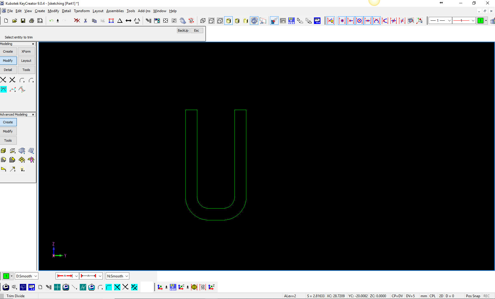
We now will create the fillets and they automatically trim. We will trim the other lines with a variety of trim commands. We had a few options for trimming since it was part of our process. Remember in manual drawing you would lightly create construction lines put in the fillets with a "hole template" and erase the lines and darken the object lines. As you can see there are no constrained dimensions. Even though these entities knew what they were, you could not edit them.
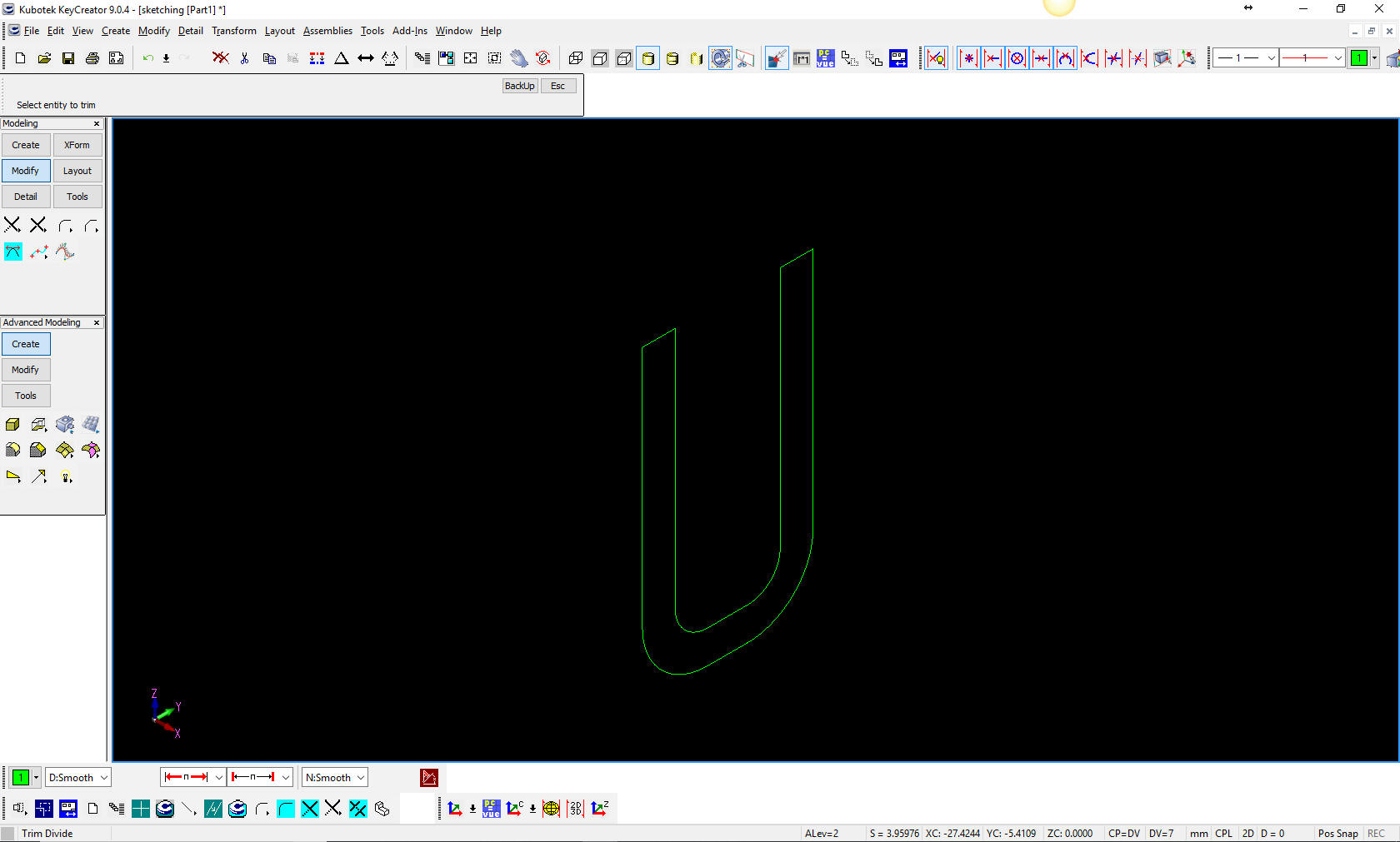
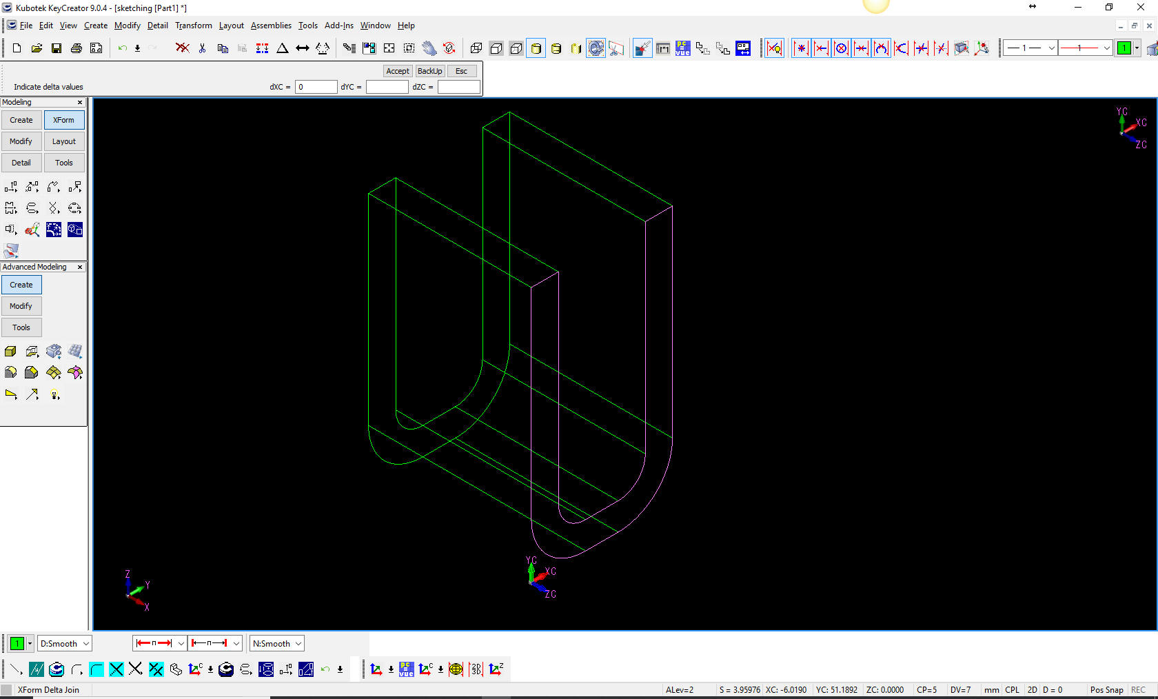
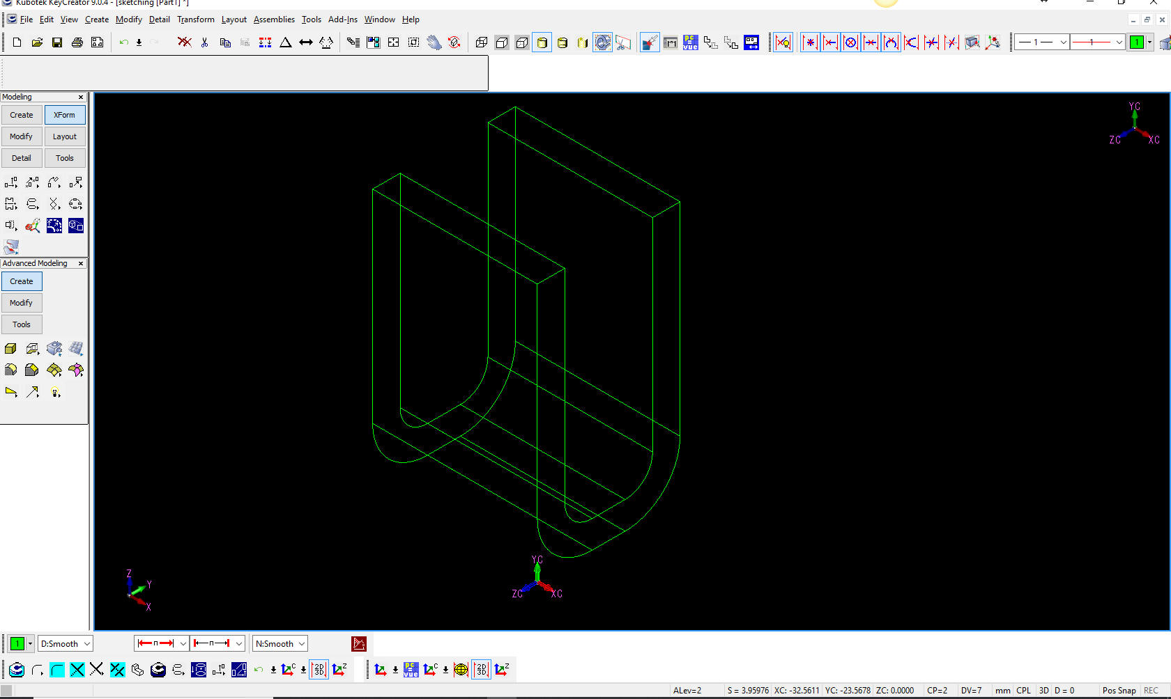
We are done with our sketch. We will turn to an iso view and set the plane separate from the view. This feature was always in CADDS 4 but was introduced to CADKEY a few years later. You can see the view coordinates different than the global system in the lower left.
Now to extrude it. Join lines will be created. This feature was included with CADDS 4. I cannot imagine how much work it would be to have to connect the dots. We just create the extrusion with the Xform delta copy and join and set the distance for 30 mm. You can not do this type of wireframe modeling in any of the popular CAD systems. But you can simulate it by turning on 3D wireframe. Again I ask, are you looking up or down at the part. That was a huge problem when we would work with the engineers. Poor guys. Now they are proud to be 3D CAD jockeys. LOL
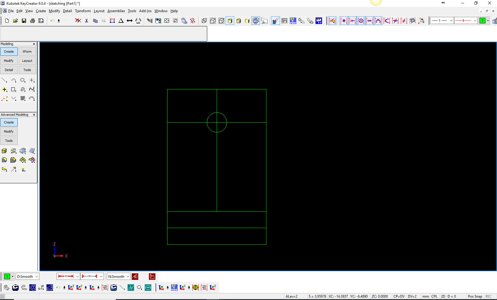
Now we add the hole. We set the CPL (Construction Plane) to View 2 or front. We set the depth on the from the end of an entity on front side of the channel. You can see the change in the gnomon or axis indicator in the upper right and the X0Y0Z0.
We will lock the depth of the plane and change the view to 2 or front and create the 6 mm diameter circle. We rarely located anything explicitly. You can see I created parallel lines and put the circle at the intersection. I still create my sketches this way, it is part of "Streamlined Sketching"
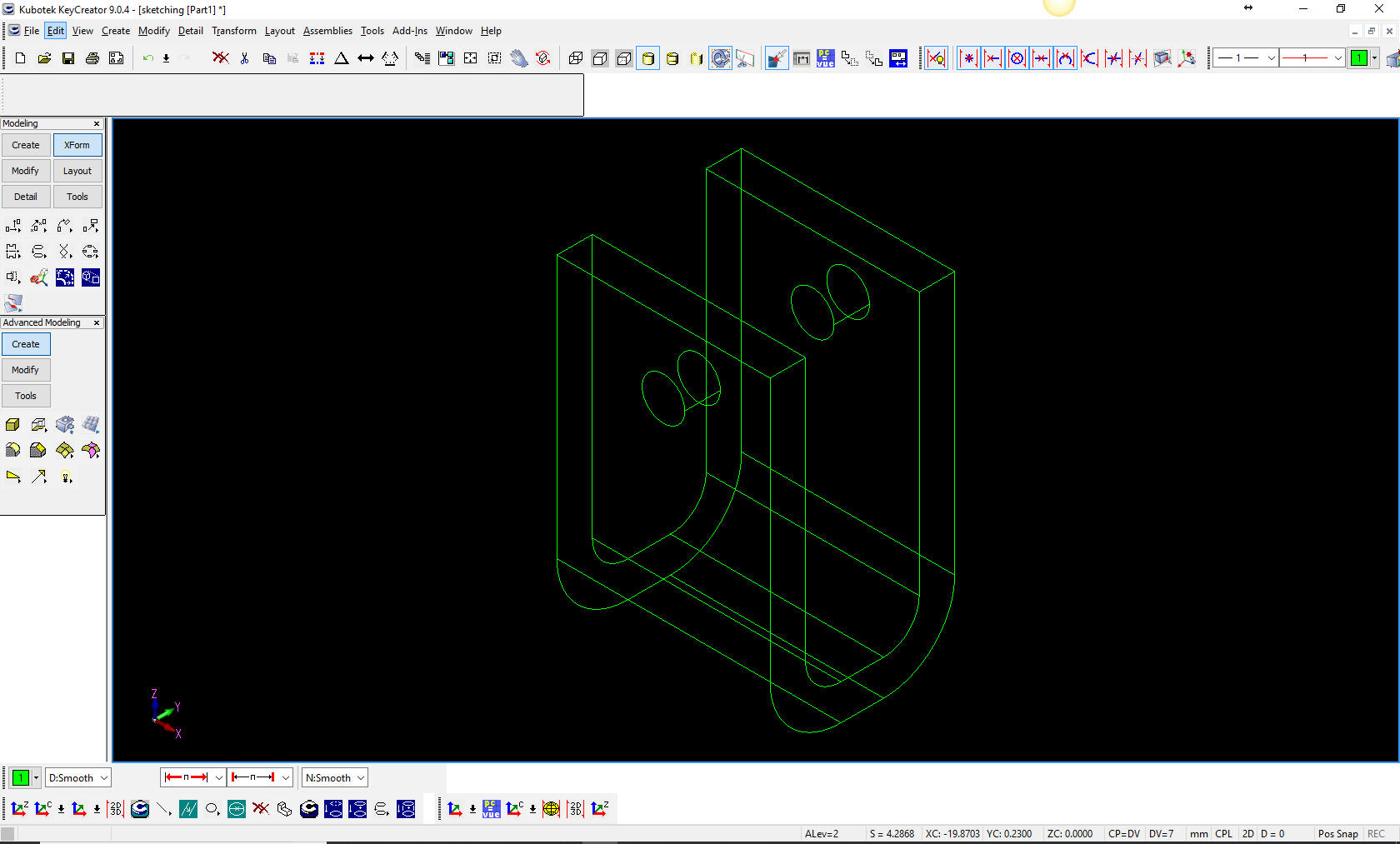
We delete the construction lines and change the instance to ISO to project the circle. This is an interesting process. First we will Xform project copy join for the first side to the inside by selecting the 2 lines that form the plane of the destination. The next will do the same command to the inside of the channel, but we will just copy. Then we will use the same command this time with join. I am hesitant to call them faces. Remember there was no concept of faces in the beginning. Welcome to probably your first exposure to 3D wirefame design. Only surfacing is worse. LOL But we are not done. The selling point of 3D CAD in the beginning was faster drawings. So let's see how that worked. It was not pretty. Since we did not draw these, the term "drawing" was a misnomer. Boeing draftsman called them the "Flat File". In the beginning this was the only purpose for the 3D model. Later they added surfacing and CNC programs like SurfCam, MasterCam and SmartCam showed up that could drive 2.5 Axis from the wireframe and 3 Axis with the surfaces. I coined the term AID (Associated Information Document) since we were now sending the 3D model and the needed pertinent additional information to manufacturing as a paper print. CADKEY had a documentation module called the layout mode. Those CADKEY guys were experience professional engineering personnel and knew that these were not drawings.
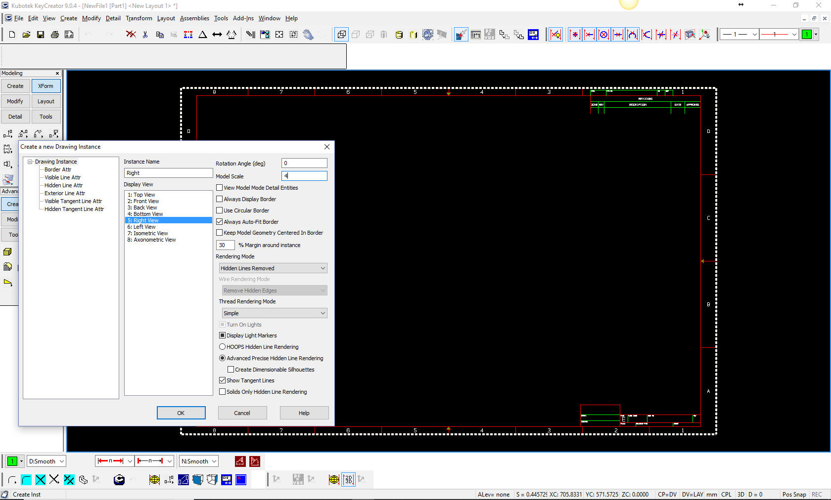
We will set up the views. Sadly, this part is very simple and needs little modification. But I will include an ISO view to show what we had to do to create a clean document (flat file). CADKEY called the views instances. Like I said these folks were a bit more with it as compared to the Pro/e folks with little actual engineering experience.
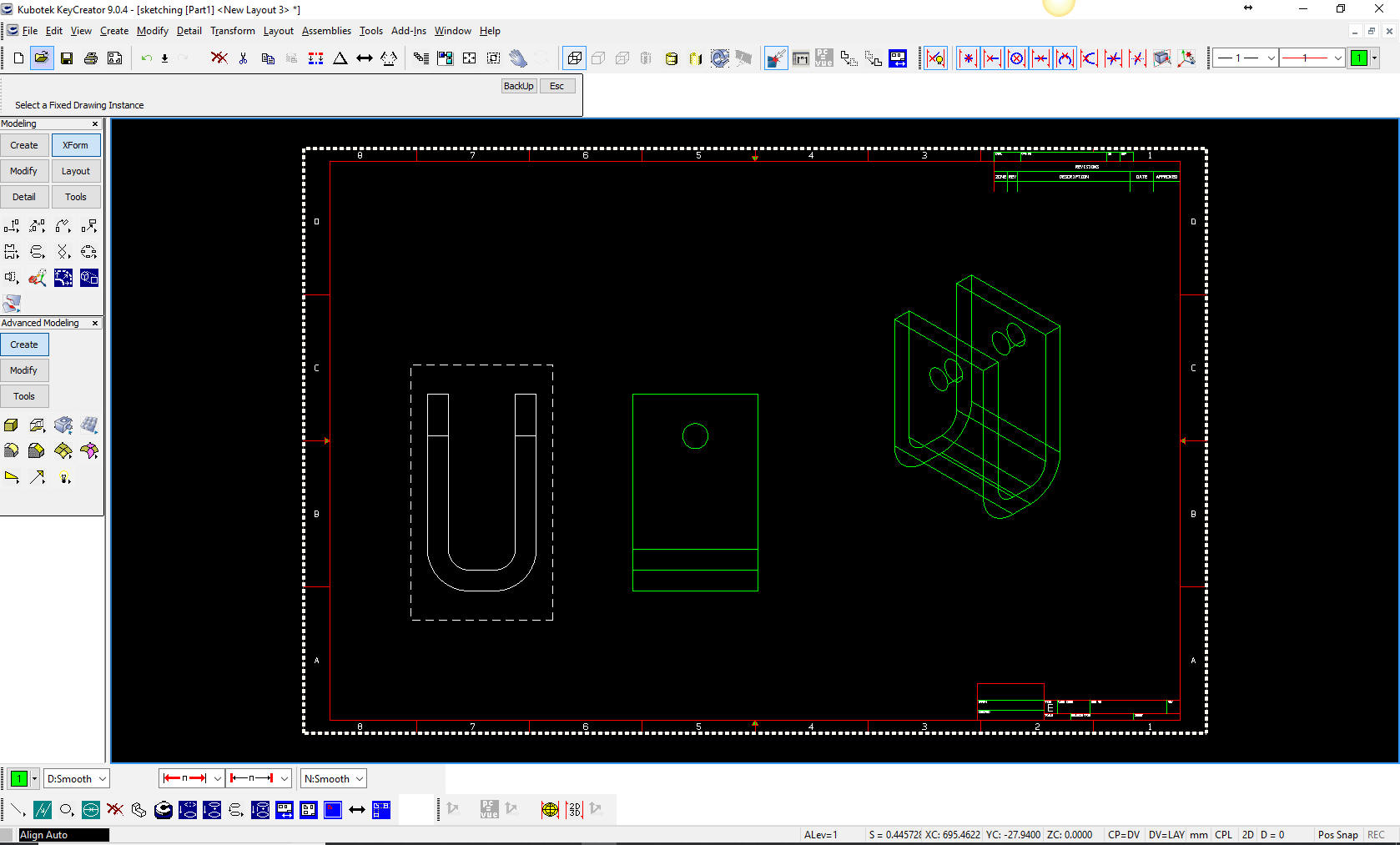
I will set up the different instances. We would have to manually align the instances. Later offered a bit more flexibility with instances but not like todays solid modeling CAD systems like IronCAD, ZW3D and others. Notice that all of the entities are displayed in the ISO view.
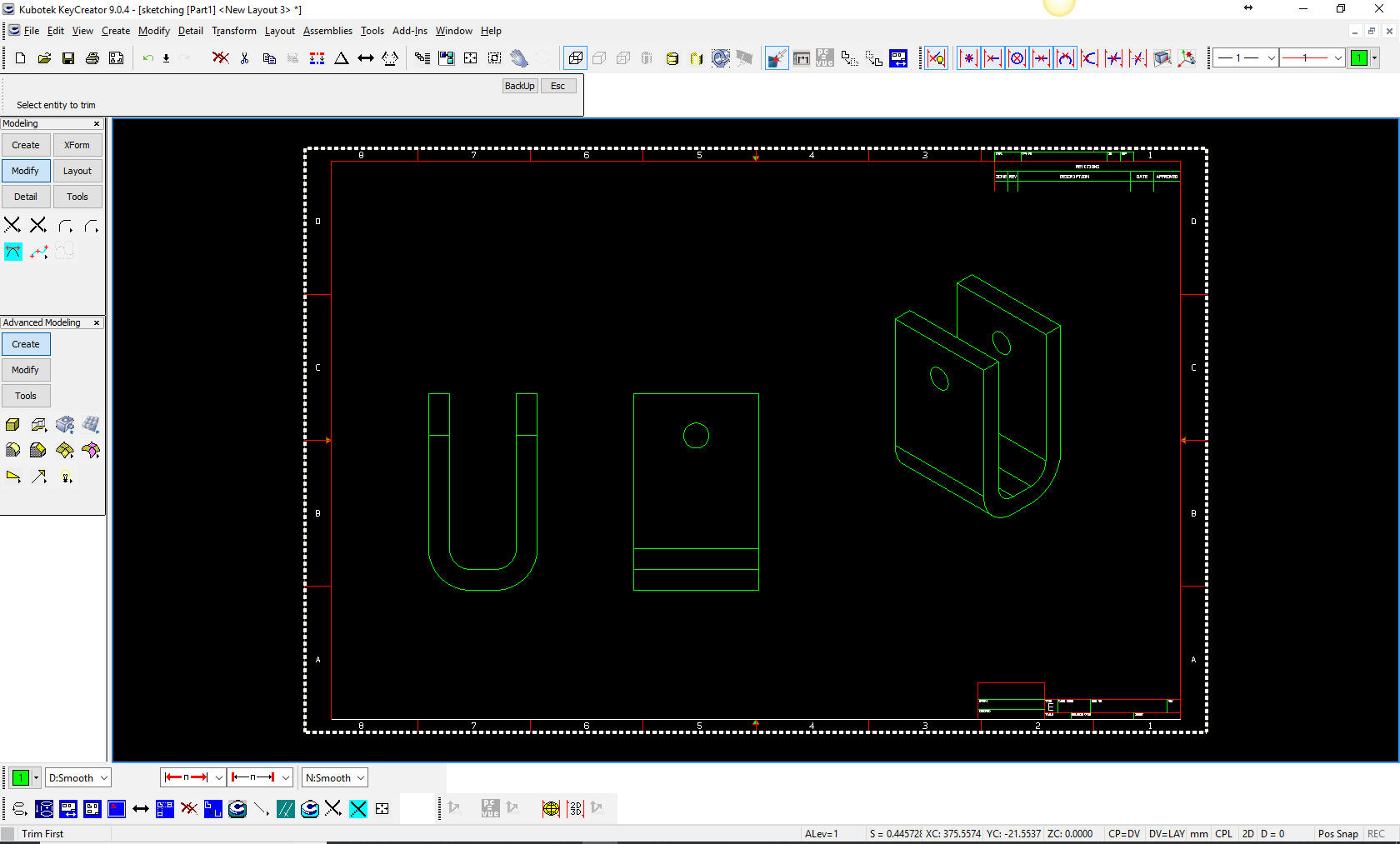
I will clean up the views. That is what we called erasing and trimming the affected entities. We call the graphics entities. Another wise generic terms by the developers. You can see cleaned up the ISO. I even had to add the silhouette line on the bottom. Can you imagine doing this with a complex part or an assembly. You can see that changes would not be easy. But it was faster than drawing on the board. It was funny that the electronic drawing package were by passed by the large Aerospace and Automotive firms by going directly to 3D.
There you go. 3D CAD Circa 1982 to 1995! CADKEY was the only 3D CAD system that was compatible with Catia 3, 4 and 5 for 20 years. Boeing probably never noticed that TECH-NET alone was responsible for making all of Boeing's suppliers completely compatible. Sadly, with the introduction of Catia 5 and PLM/MBE/MBD they have made that compatibility incredibly costly.
So there you go 3D wireframe design in a nutshell. It was done like we did it on the drafting board. Industrial/mechanical engineering never use point to point drawing. We slid triangles, T-squares, Parallel bars or drafting machines. We use circle templates for circles up to a couple of inches then we would use a compass. AutoCAD was and still is based on architectural drawings. Mostly drawing from point to point using lines. Infact the way you trimmed two intersecting lines was to put in a "zero" fillet. Pro/e sketching is very point to point as you can see in the example of the Fusion 360 presenter. Then the added dimensional constraints are very time consuming even on a simple part like this. You will see how Streamlined Sketching and Feature Based Modeling can increase productivity 5 to 10x. One more interesting point, when surfacing showed up it did not add to documentation creation. While you could render it it was only useful for 3 axis CNC and 3D printing. We would send the model as an IGES file along with the print of the "flat file". Enter Solid Modeling Pro/e, the only solid modeling system designed from the ground up, showed up in 1988. It was expensive, very complicated and delivered on a single UNIX workstation, making it available to the single user and much cheaper than the mainframe networked Computervision's and Catia's at the time which were just beginning to dabble in solid modeling. But its history based design was unique and quite viable for initial design. When it came to changes it completely failed in so many ways and still does. In 1995, solid modeling hit the PC! I was
selling CADKEY and a third-party company developed FastSolid. It
was a Boolean modeling system. Which you designed by adding or
subtracting shapes or by trimming. This was followed by the very
powerful, flexible and productive direct editing of today. As you use direct editing for your design you used a
mindset like machining or manufacturing. Which was a bit more
realistic concept in 3D modeling. You basically designed like the part would be
made. Also in 1995 there are many solid modeling
CAD systems showing up due the the release of the Parasolid and
ACIS solid modeling kernels. At that time I was introduced to
Trispectives that became the basis for IronCAD developed by a company that
was an OEM for CoCreate, now Creo direct. It was a drag and drop of smart shapes
from a catalog. They incorporated much of the direct edit
functionality which made IronCAD the only truly
integrated history/direct edit modeler. You use both concepts
freely in your design. But you basically start by dragging and
dropping positive or negative shapes, pushing and pulling
features to create your design. You also have robust sketching
when the need arises. So, it is the best of both worlds. With direct edit you have a more real-world view point of how the parts are made, plus a very flexible way of making changes with no limits. With the introduction of Solidworks in the
same year, we had the duplication of the Pro/e paradigm on the
PC.
This is quite different than the direct
edit concept. I found this as I was doing product comparison
with Solidworks and Fusion 360. I noticed that the CAD designer was sketching
point to point and dimensionally constraining everything. When they could have created a basic shape and added
another shape, used shelling or creating a blend, they would
create time consuming overly complicated constrained sketches,
as shown here, even on very simple parts.
I realized this was a industry wide mindset. I found even
old board designers that was a Pro/e designer from the very
beginning falling into this convoluted modeling process. I bumped into this Creo expert. He could
not conceive not using constrained sketching. He did the model
to show me. It was just like the SW user. He said it only took 7 steps!!
But he didn't consider each sketched entity and constrained
dimension a step. He would not even look at the way I told him
to give it a try. Create a cylinder, add blends, create the center
extruded cylinder cut, split and shell for the basic shape. I gave up on him. But I should have asked
him if he ever tried Creo Direct. The direct edit only package
from PTC.
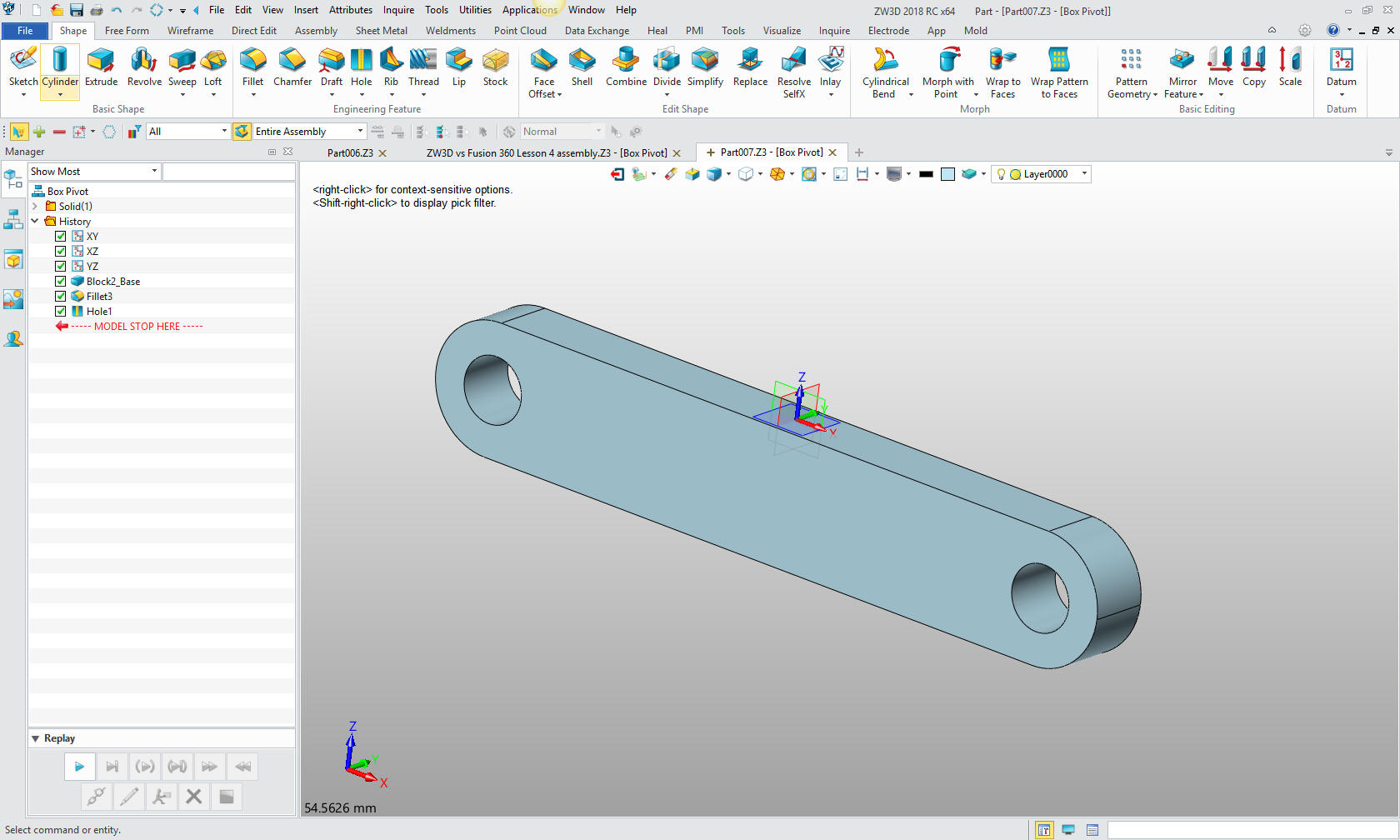
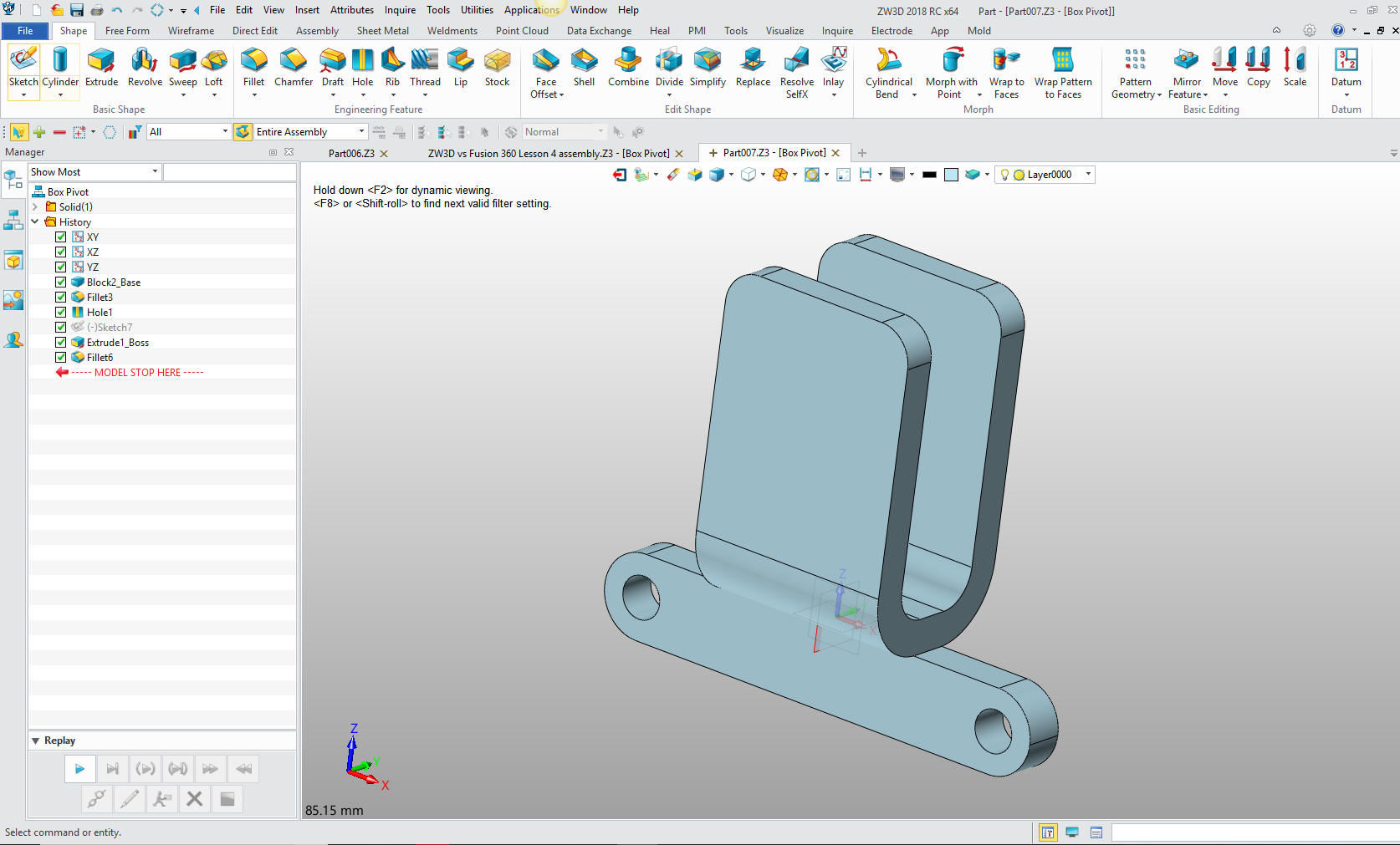
Here I will do these in ZW3D that is basically a
sketch based system. IronCAD is first, drag and drop design,
sketching is a secondary process. I will be using streamline
sketching to save time. You can see the complete exercise here.
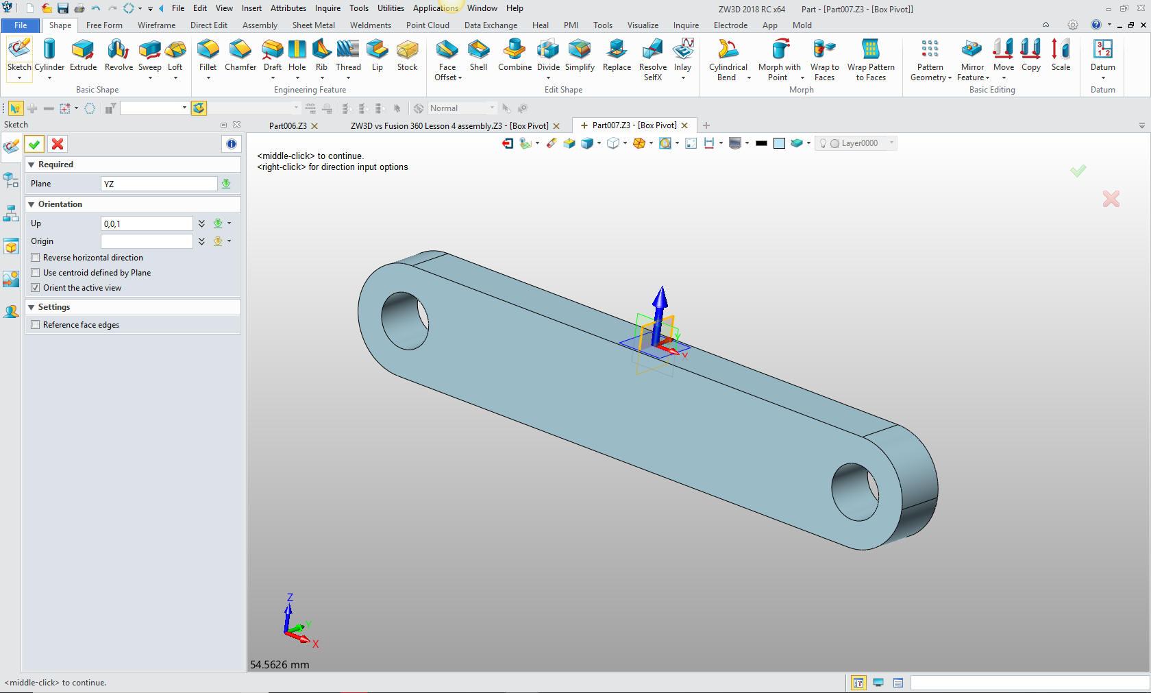
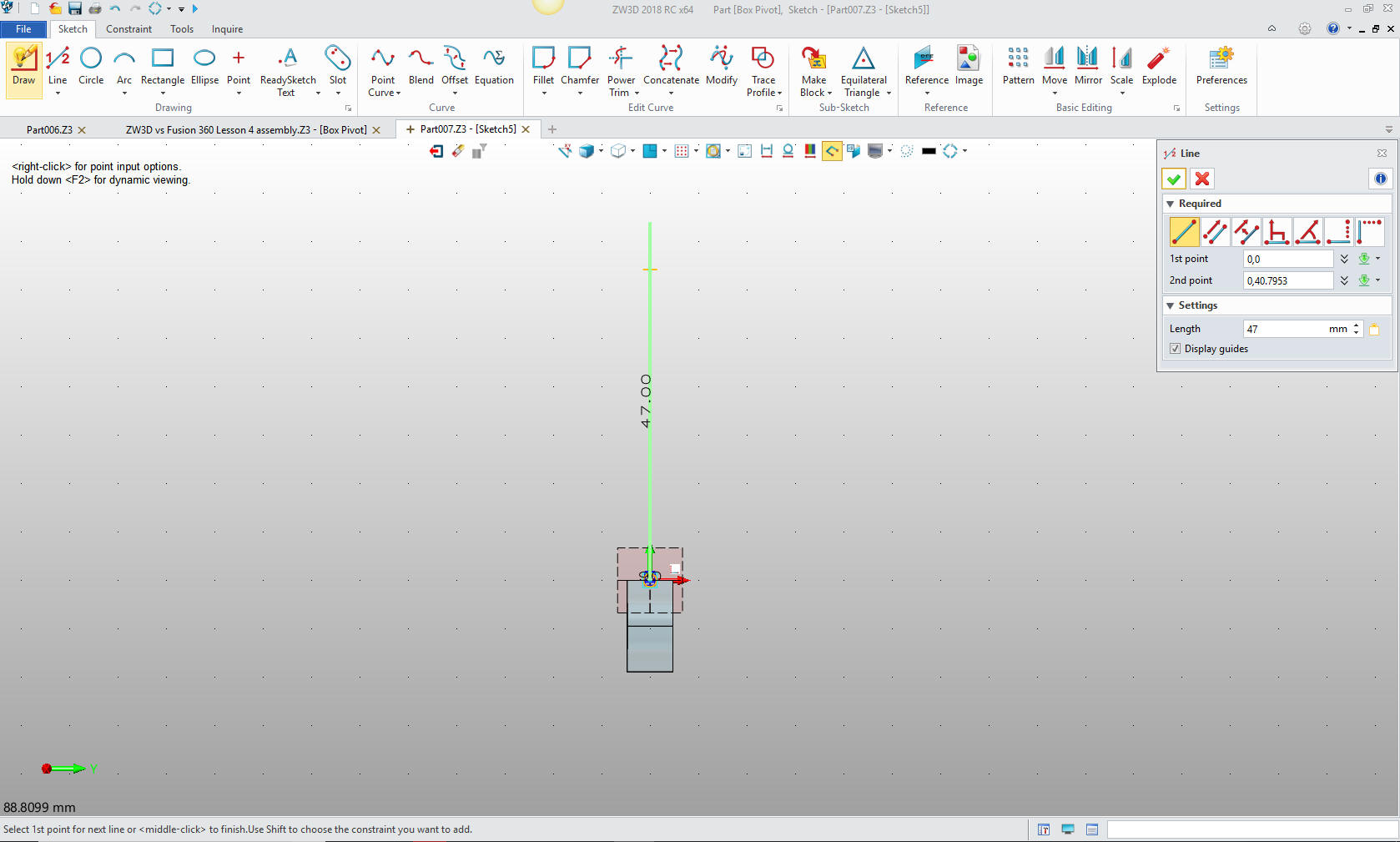
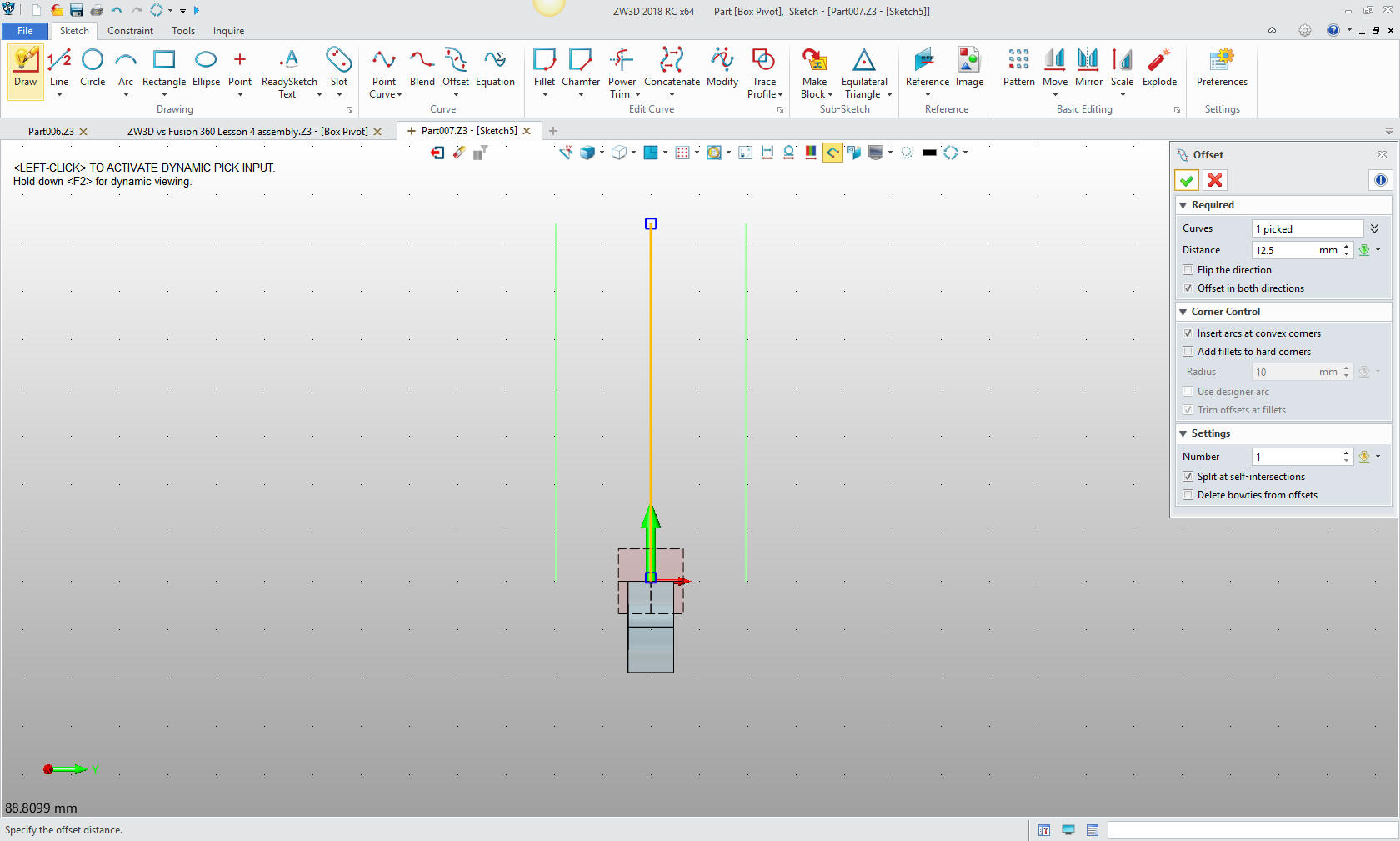
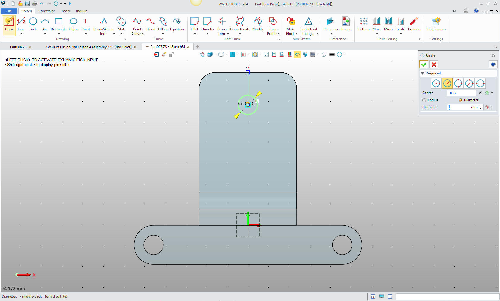
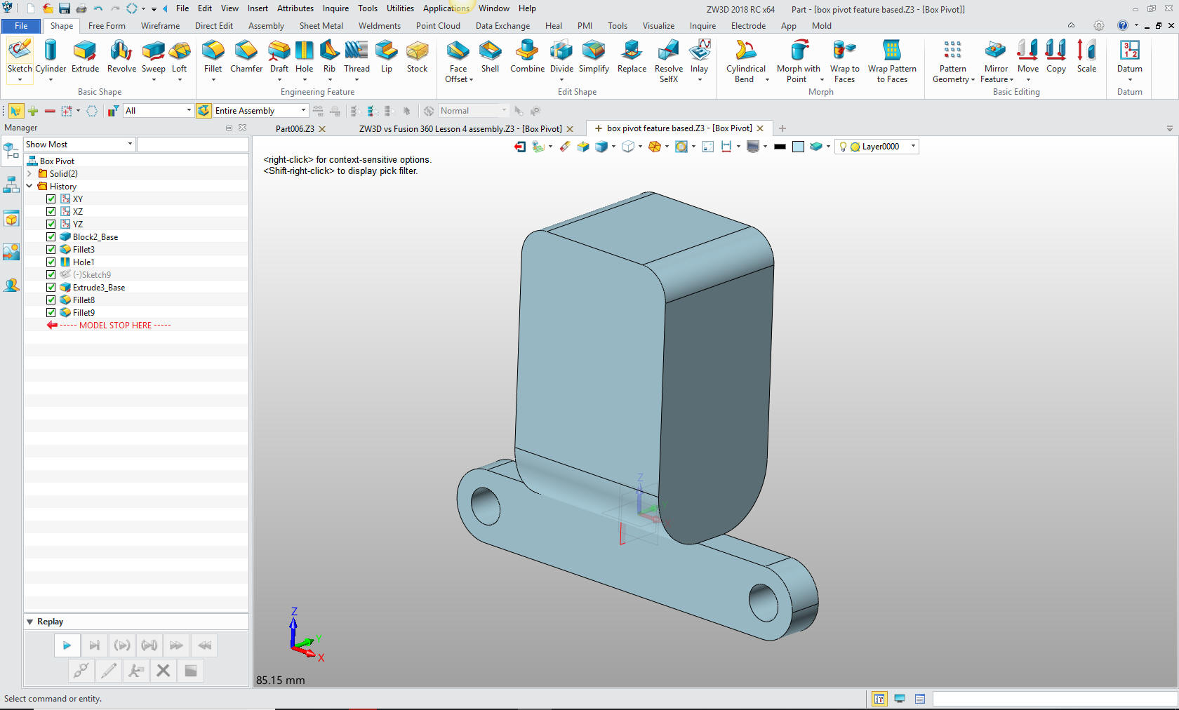
Let's get started Please view the incredible convoluted way the Fusion 360 user sketches this part. It starts at 3:55 in the following video Fusion 360 Challenge of the Month: December 2016 - Part1We will create a “U” shape. 1. Streamlined Sketching Based Design Mindset We start with the bottom support already create.
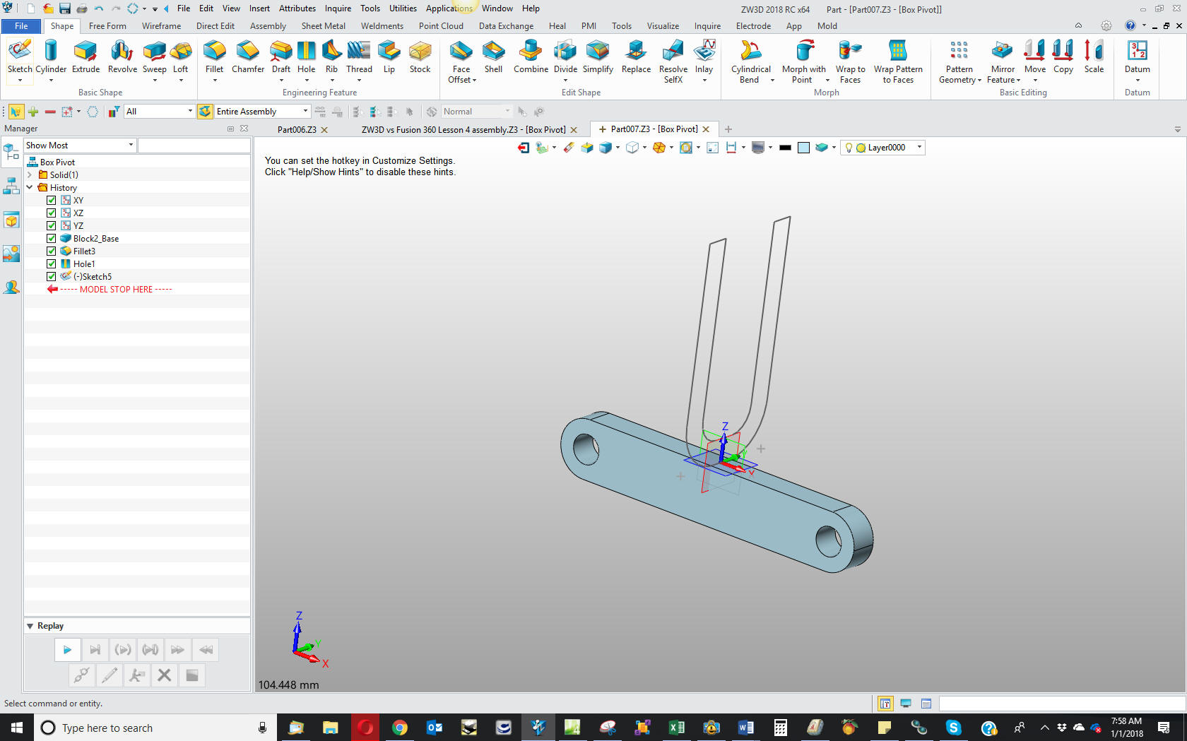
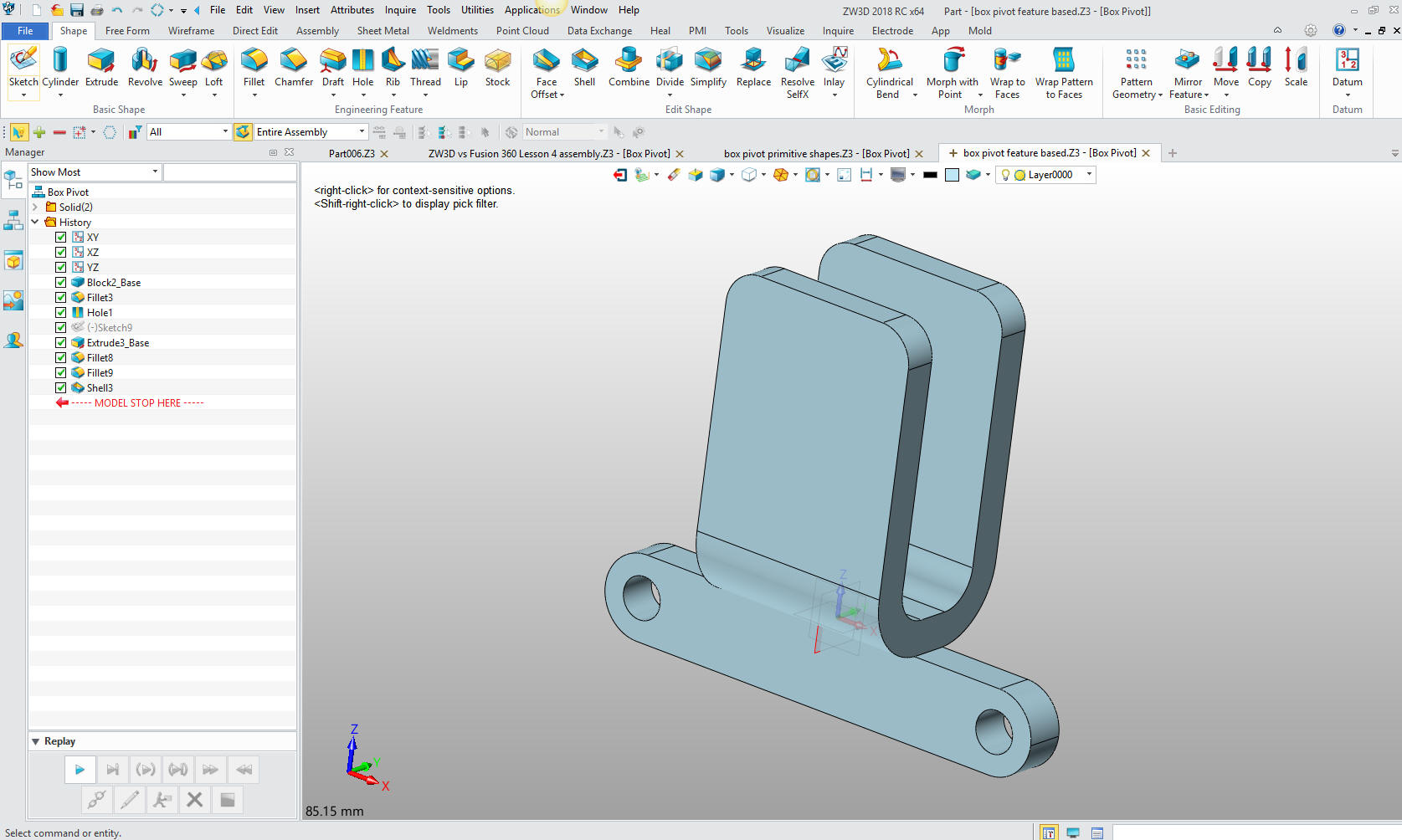
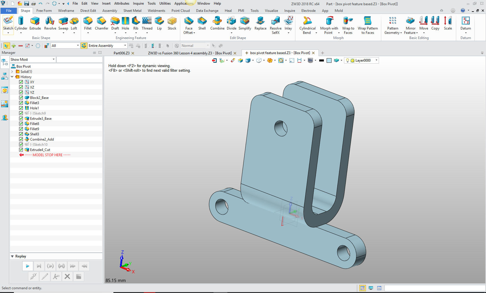
Exit the sketch and extrude the circle, creating the hole. We are done much, much faster than the Fusion 360 user.
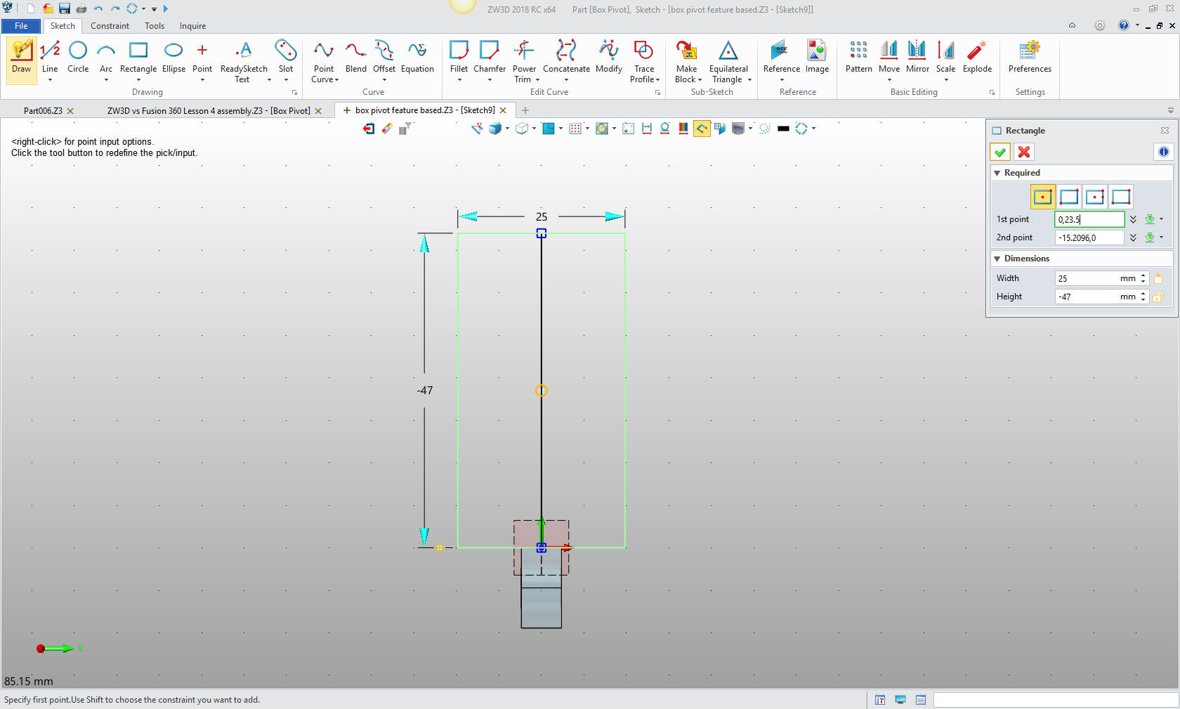
We now create a reference line and then a center based rectangle using the mid point of the reference line. Again we are using Streamline Sketching with no constrains.
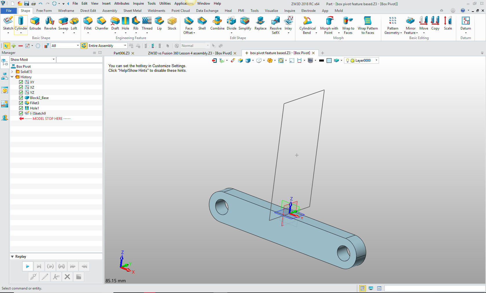
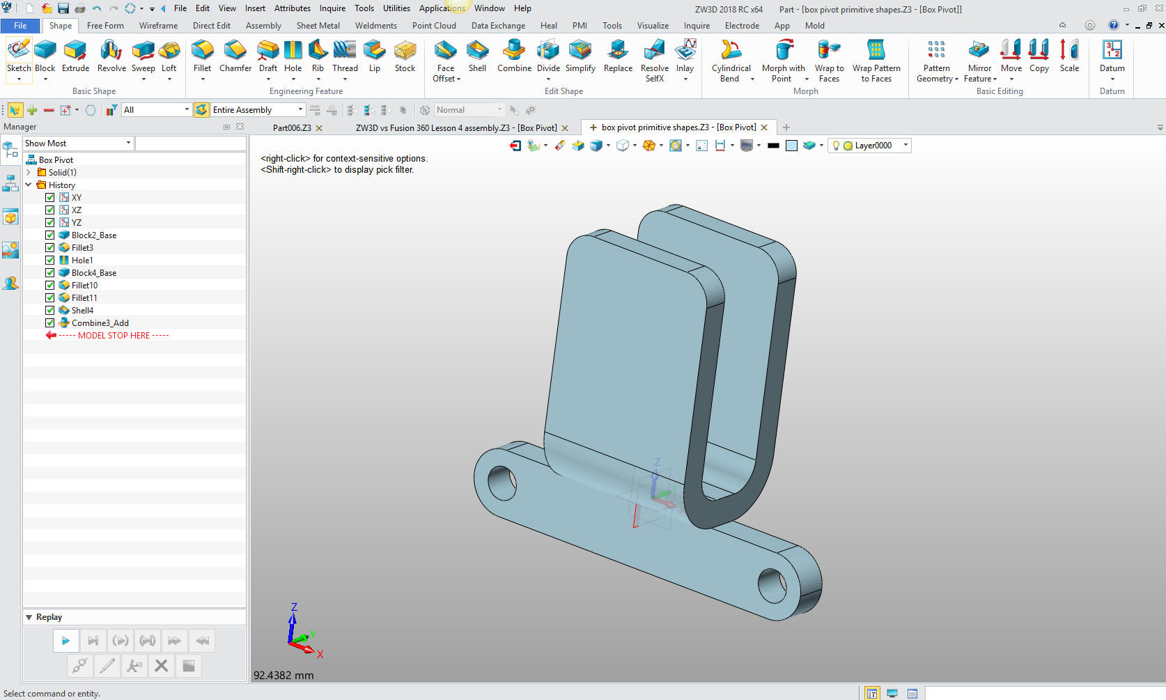
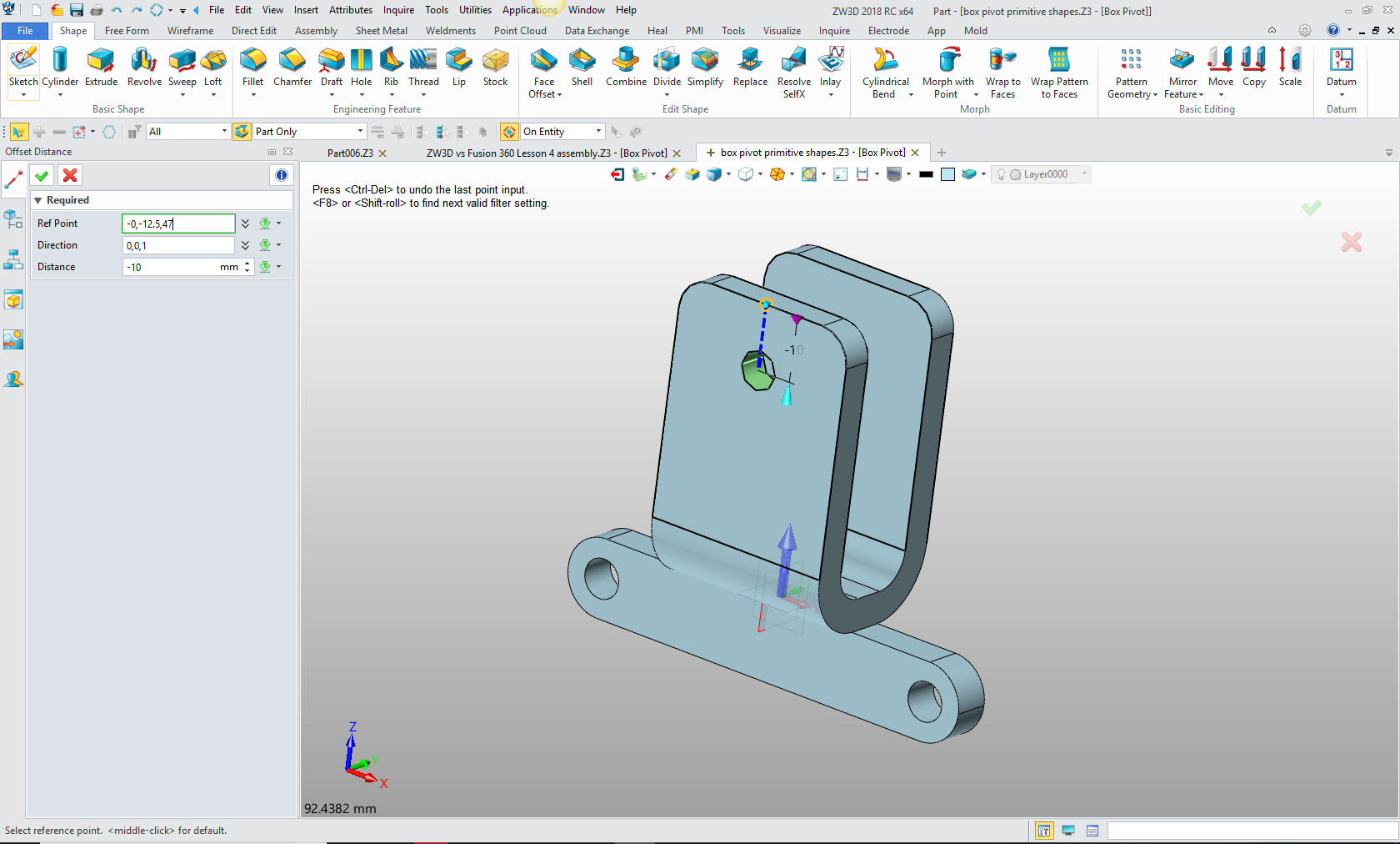
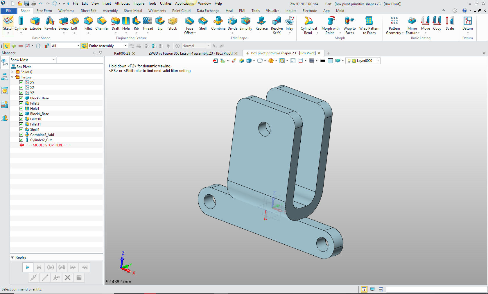
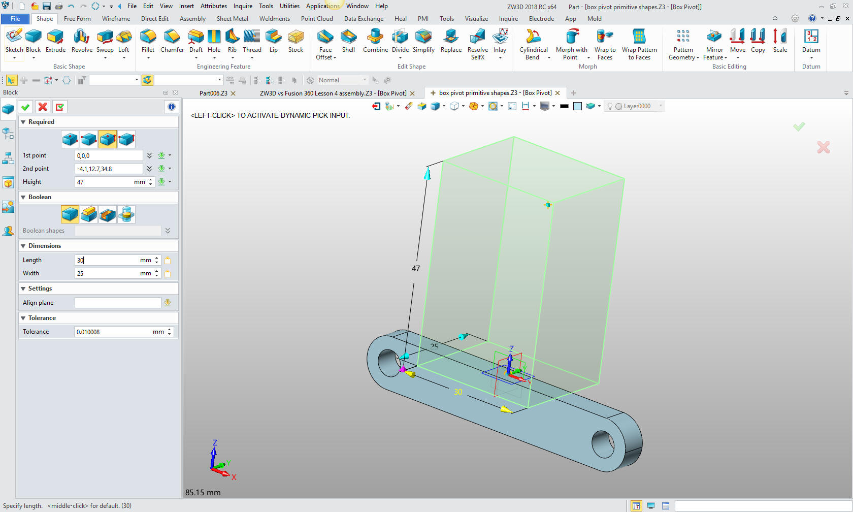
3. Bonus: Designing with Primitive shapes! No Sketching at All.
And we are done.
All three parts are sent off to manufacturing and they load them into their CNC package. Nope, no difference. Conclusion This shows that Feature Based Modeling and Streamlined Sketching is superior modeling paradigm as compare to constrained sketching. Not twice the productivity but 5 to 10 times. Give me a call if you need more information or introduction to this concept. It will work with any 3D MCAD system. If you would like to try ZW3D please download for a 30 day evaluation.If you would like more information or to download ZW3D Give me a call if you have any questions. I can set up a skype or go to meeting to show this part or answer any of your questions on the operation of ZW3D. It truly is the Ultimate CAD/CAM System.
TECH-NET Engineering Services!
If you would like more information or to download ZW3D or IronCAD If you are interested in adding professional hybrid modeling capabilities or looking for a new solution to increase your productivity, take some time to download a fully functional 30 day evaluation and play with these packages. Feel free to give me a call if you have any questions or would like an on-line presentation.
|