 | |
|
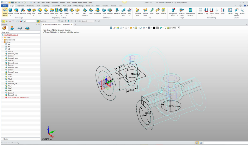
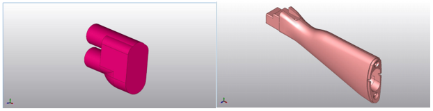
November 17th, 2016 3D CAD Precision or Free Form MorphingMorphing allows you to manipulate faces arbitrarily or
precisely. This is unique design process used in different industries.
Mostly Industrial Design where aesthetics is a very important part of the
design. Date & Time: Thu, Nov 17th, 2016 at 10:00 am PST RegistrationPlease register for the above meeting by visiting this link: http://joe114.enterthemeeting.com/m/6RG7MTKC Once you have registered, we will send you the information you need to join the webinar.
If you think ZW3D can enhance your existing system with increase
productivity, functionality or compatibility feel free to give it a try. Download a fully functional 30 day evaluation
TECH-NET and GreatLakes3D are offering a series of 3D CAD/CAM informational webinars focusing only on Industrial/Mechanical Engineering, Manufacturing and the generic operations of all the 3D CAD systems. 3D CAD has been much more than a profession for me. It has been a passion for over 34 years. I have sold, supported, trained 3D CAD and provided engineering services. I have work with most of the 3D CAD systems and have found that most work pretty much the same. The only difference being the user interface. The 1980's - 3D CAD - The Beginning I met Randy, of GreatLakes3D, a few years ago. Both of us have been in the 3D CAD world for decades. Randy came from the manufacturing (CNC) side and between the two of us we provide support from product design to product manufacturing. We will start with the setup and beginnings of the creation process. We will break down the process to show the simplicity 3D CAD. We will be using ZW3D, but this can be related back to any 3D CAD system. All 3D CAD systems basically work the same, the difference being the user interface. These will be a 30-minute presentations with 15 minutes of discussion. Remember we are focusing on generic operations not the operation of the specific 3D CAD system. Please pour a hot cup and just watch or join in!! Joe Brouwer 3D CAD is 3D Graphic Design
We will go through the most commonly used functions as they are used in 3D CAD design. Each of these beginning sessions will also include the setup of creating a new part or assembly. As we move to more advanced design tools will work with existing work. Who would be interested in learning these basics?
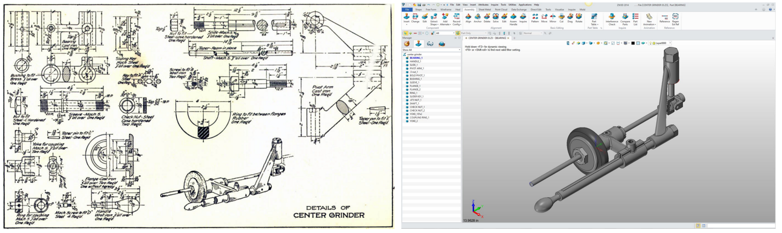
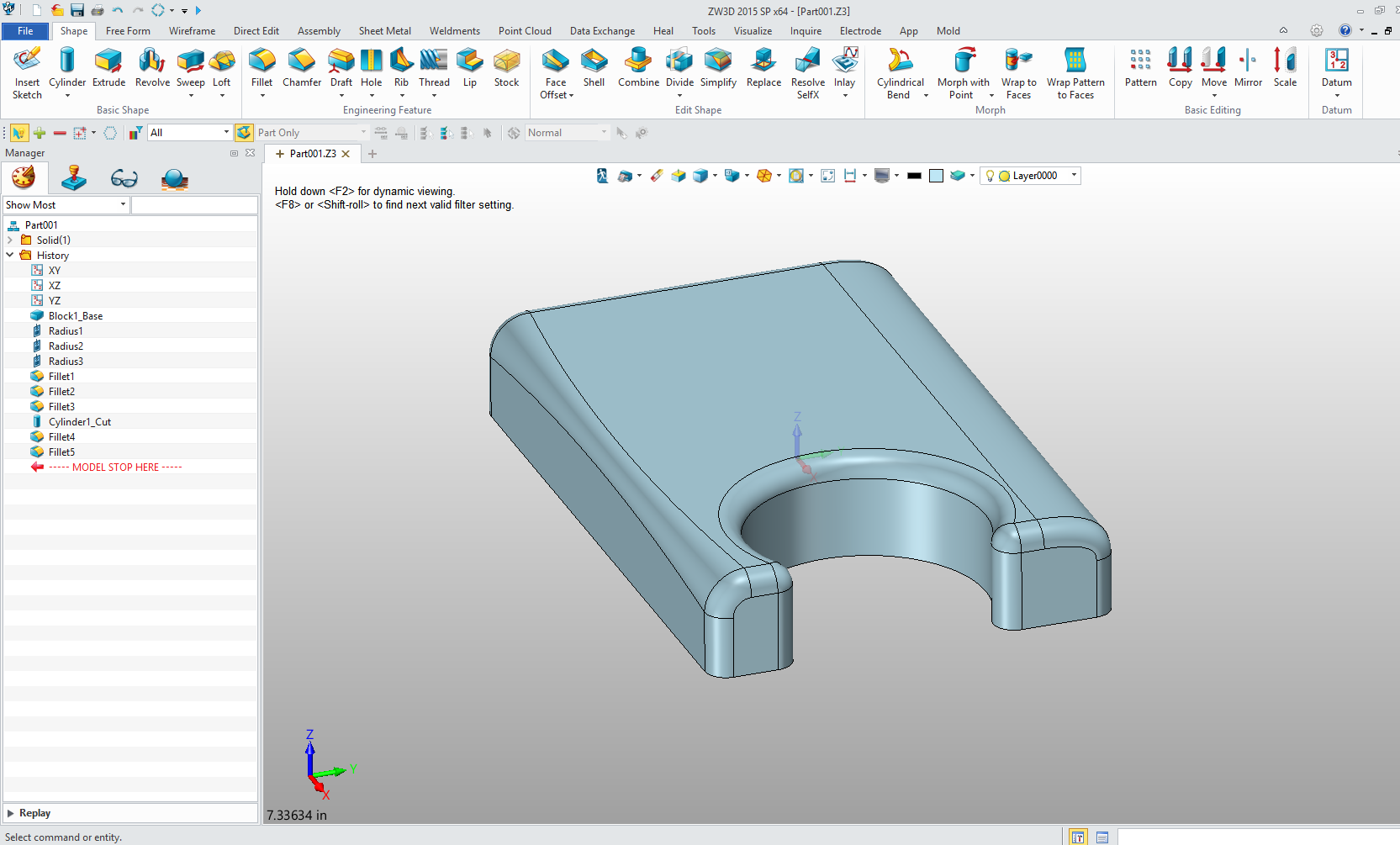
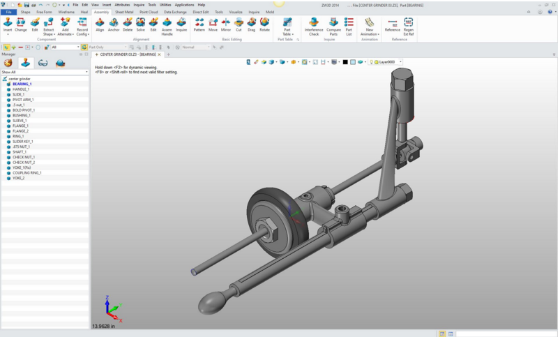
You can see how some of these commands and functions
are combined in the following article. Watch as I convert this ancient drawing
to a 3D
model and document it.
| |
|
December 1st, 2016
Surfacing
– So much hype? There is a lot of hype about
surfacing. Truth be told it is only used by 10% of the designers. There are two
levels of Surfacing the intermediate which basically supports our solid
modeling and the stand alone surfacing.
Standalone surface design is a bit tedious. Based on wire frame
design. Basic surface design aids to creating faces that are not easily created in
solids. Advanced surface design is used by 2% to create surfaces that are in
the realm of correctly creating visual based shapes like cars and other aesthetic
shapes. These folks call themselves digital sculptors.
We will keep to the basic levels of surfacing as it
relates to industrial/mechanical engineering.
December 15th, 2016
Hybrid Modeling –
The future of 3D CAD. This is the mixture of wire frame, surfacing and
solid modeling working together. While many will not require this level of
design it is very nice to have it available. The different design paradigms
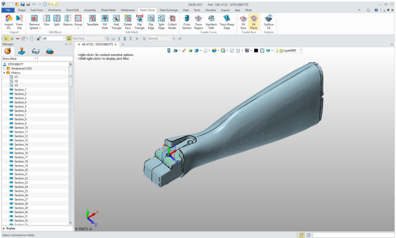
coexist in one design environment, offering design without limitations. 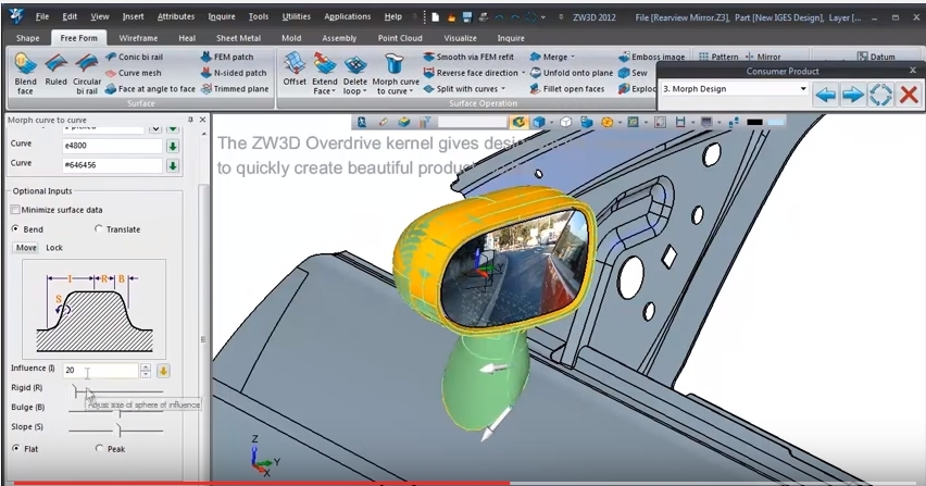 Date TBD Reverse Engineering To do reverse engineering you have to be able to
utilized scanned data. Extrapolate and develop the necessary graphic to
recreate the original parts. You have to have a highly functional Hybrid
Modeler to make this happen effectively.
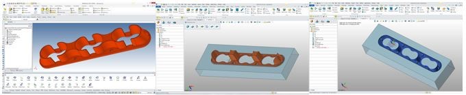
Date TBD Mold Design I am a plastic product designer. I utilize the
core/cavity split to evaluate the correctness of my parts. But mold design
is unique and needs the many required standards available to create the
molds. We will see how these work together. Again most mold design package
work similarly.
Date TBD
Integrated CNC –
Quickest design to manufacturing solution There are very few integrated CAD/CAM systems. We are
working with the most cost effective package. But again all are very
similar. If you are a designer, student, manager, etc, that is interested in
how CNC works or a professional CNC programmer interested in how others work
this is the webinar for you. 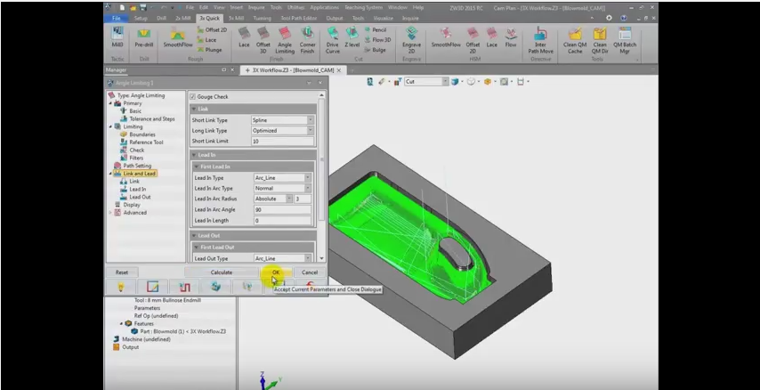 DATE TBD Extrude – The work
horse of 3D CAD I would say that 80% of 3D CAD design is based on the extrude command. We will go through the basics of how we create extruded shapes.
DATE TBD Spin or Revolve This command is used probably 10%. Now there are
industries like Gas Turbine that much of the work would be done with this
command. But in most design it is rarely utilized. 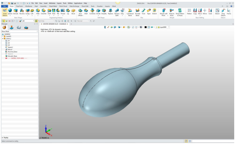
DATE TBD
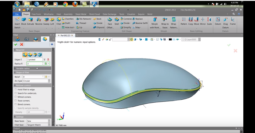
The Incredible Blend or Fillet Radius The blend or fillet radius seems like a simple command. But it can become very complicated as you get into more complex machine or plastic parts. There are a variety of blends we can use depending on the type of design. If you are an Industrial Designer there are special blends to add an aesthetic value. We will show you the different types.
DATE TBD The Flexible Sweep Command This is a command I rarely use, no more than 5%. I
have used it to sweep a unique shape that would have taken a combination of
the extrude and revolve commands. Also it is the only way to create a shape
down a contour. I am sure this would be used in creating tubes. 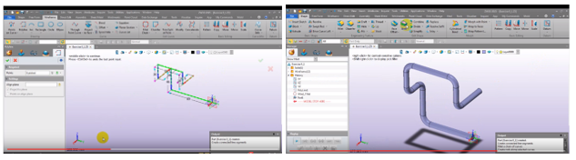 DATE TBD The Mystery of Helical, Spiral and Coil Design Exposed! This is a specialized function of the sweep process.
Again this is rarely used and being that, it can be a bit of a mystery since
you have to go through a learning curved every time you use it. But you will
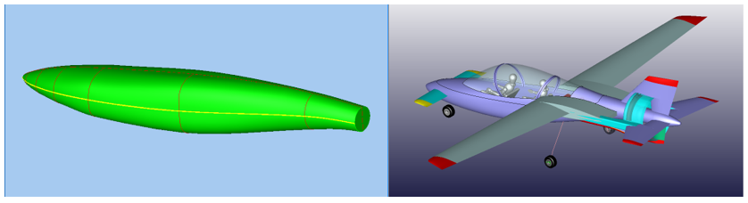
see how easy it is. 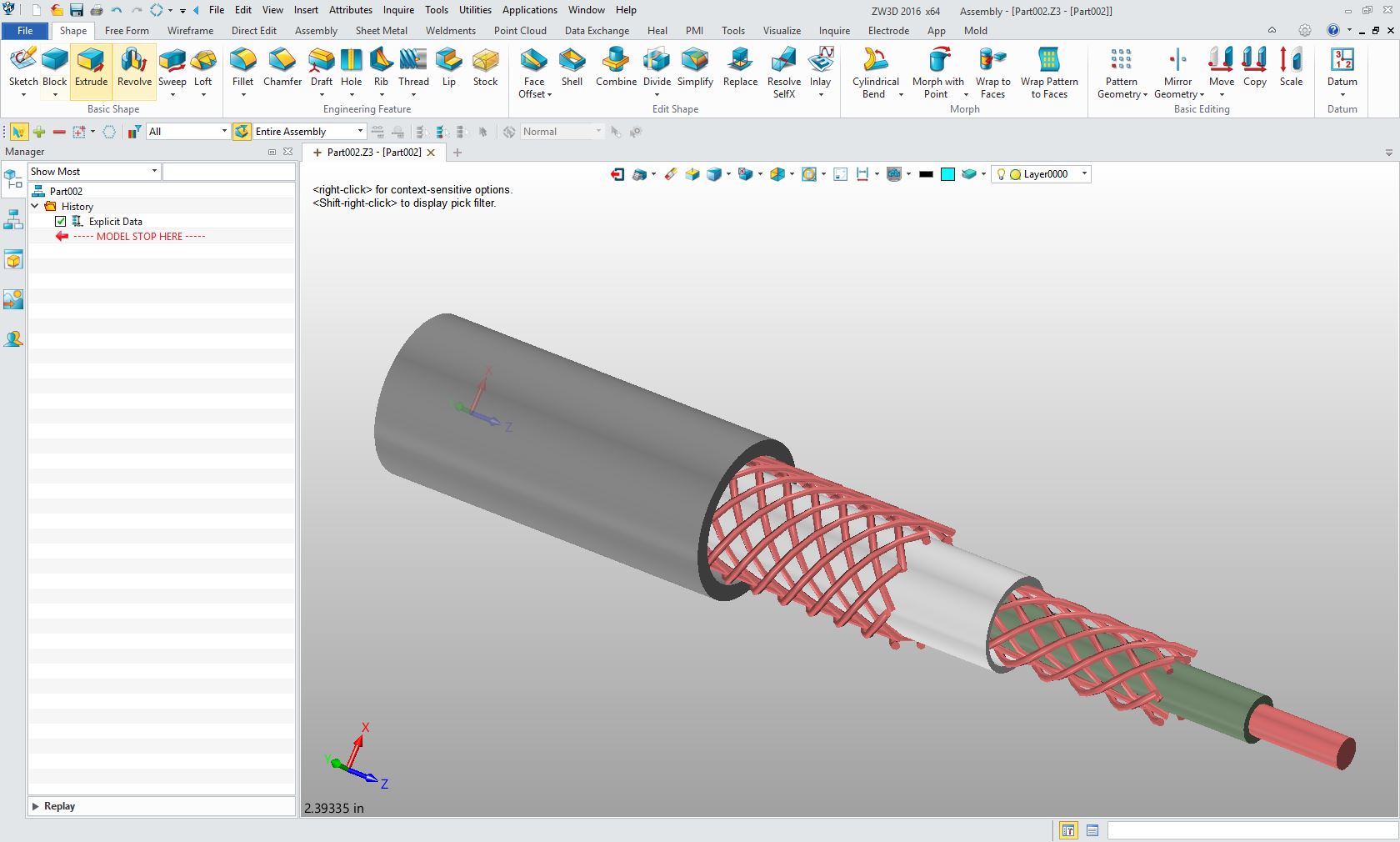  DATE TBD The Powerful Loft Command This another command I rarely use, no more
than 5%. I have used it in creating a fuselage for an experimental aircraft.
It is a bit of a convoluted command made up of a combination of sketches. It
is much more flexible as a surface design function, which we will get to in a
later webinar.
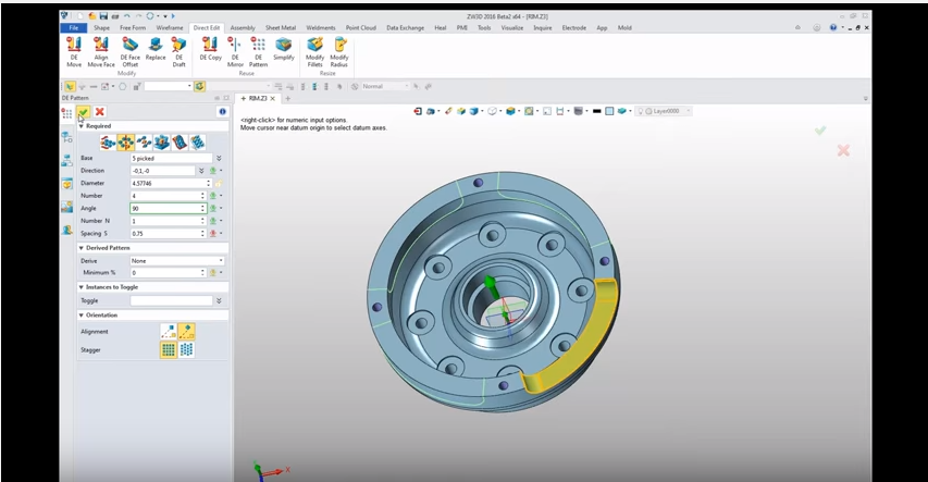
DATE TBD
Direct Edit Relief
–
Adding flexibility to our design All 3D CAD systems have attempted to make this functionality
available. While history based design is very good in the conceptual design
process is can become very difficult, even impossible when it comes for
design modifications or changes. We all know change is the only constant in
design. Integrated direct editing offers an incredible flexibility to do the
changes. Not being dependent on parent/child relationships it allows
complete freedom and flexibility to easily complete projects.
TBD Boolean Design – The beginning of solid model This is a unique design process. It was the very first design process used in solid modeling. It is a bit of a subset of direct edit. Many times it is easier to create a positive part and Boolean subtract from a base part. This also a rarely used process but can add simplicity to our design process.
TBD
Multi-Object 3D CAD Design
–
The Most
Productive CAD System Feature Many call this “top down” or “in context” design.
This is where all of the components are included in one file. Where you can
work with any of the parts in an assembly. No external parts until the
design is complete. Many times you can just leave the parts in the same file
if it is a one-person project.
TBD
The Integrated Drawing
–
Simplifying PDM This is unique to ZW3D and a couple of other
programs. It actually makes the Mult-Object concept much more viable. Having
the drawing included in the part or assembly files eliminates much of the
file management problems. Many of you probably don’t know this exist. It
truly is worth the look. 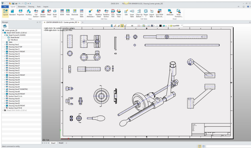 We hope you can attend them all. Please feel free to contact Randy or Joe if you have any questions. Randy Biebel - 814-823-2262 or randy@greatlakes3d.us Pennsylvannia Joe Brouwer - 206-842-0360 or joe@tecnetinc.com Skype - tech-net-inc Seattle, Washington |


TECH-NET ASSOCIATES | RENDERING OF THE MONTH | CAD•CAM SERVICES
HARDWARE | TECH TIPS | EMPLOYMENT | CONTACT