|
LEARNING 3D MECHANICAL CAD
3D CAD is now a requirement for mechanical engineers. Today
we design in 3D. It should have been called 3D drafting and
the engineers would
probably
not
have
been stuck with the menial
task of form, fit and function design and engineering
document creation that was previously the
domain of the draftsman. But that is water under the bridge.
Engineers are
today's
"3D CAD Operators" first.
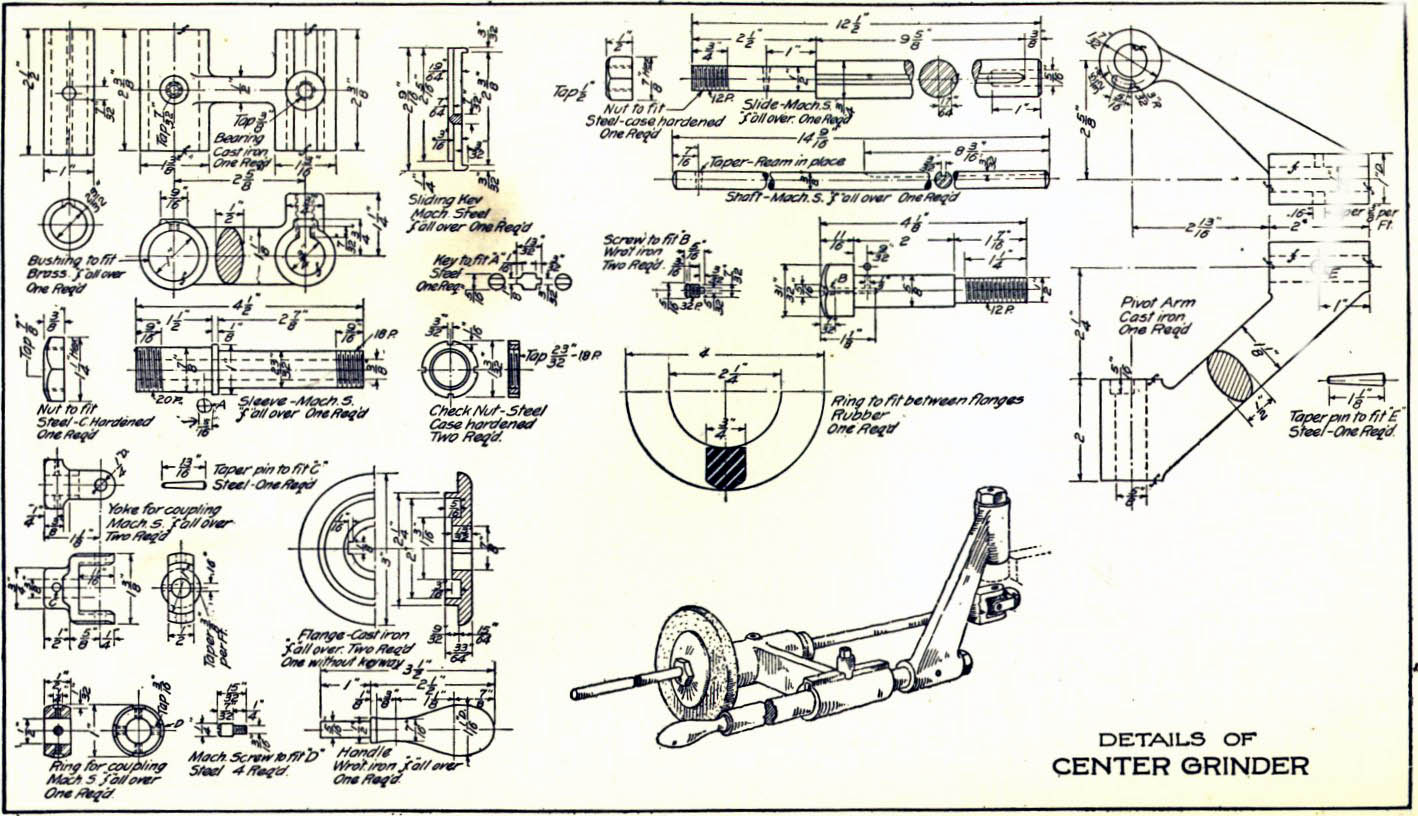
Educating the New 3D CAD Engineer - 2015 Basically all mechanical solid modeling 3D CAD systems are the same. Some are history based only, some with both history and direct edit and some are direct edit only. But they all have extrude, spin or revolve, loft and sweep as their basic construction tools. I have had the above drawing on one of my other articles and I decided to use it to sharpen my skills with ZW3D. I have found that creating solids from a drawing is the very best way to gain experience in 3D CAD. They not only offer many modeling challenges but they also let you see how parts are designed. The above assembly is a great place to start. Feel free to copy and print it. All You Wanted to Know About Drawing to 3D Conversions All 3D CAD systems today are mostly generic so lets take a look as we start this project in ZW3D. ZW3D is unique that you can do the part, assembly and drawings in one file. You can even do scratch 2D drawings like Autocad or Draftsight. Here is our completed assembly 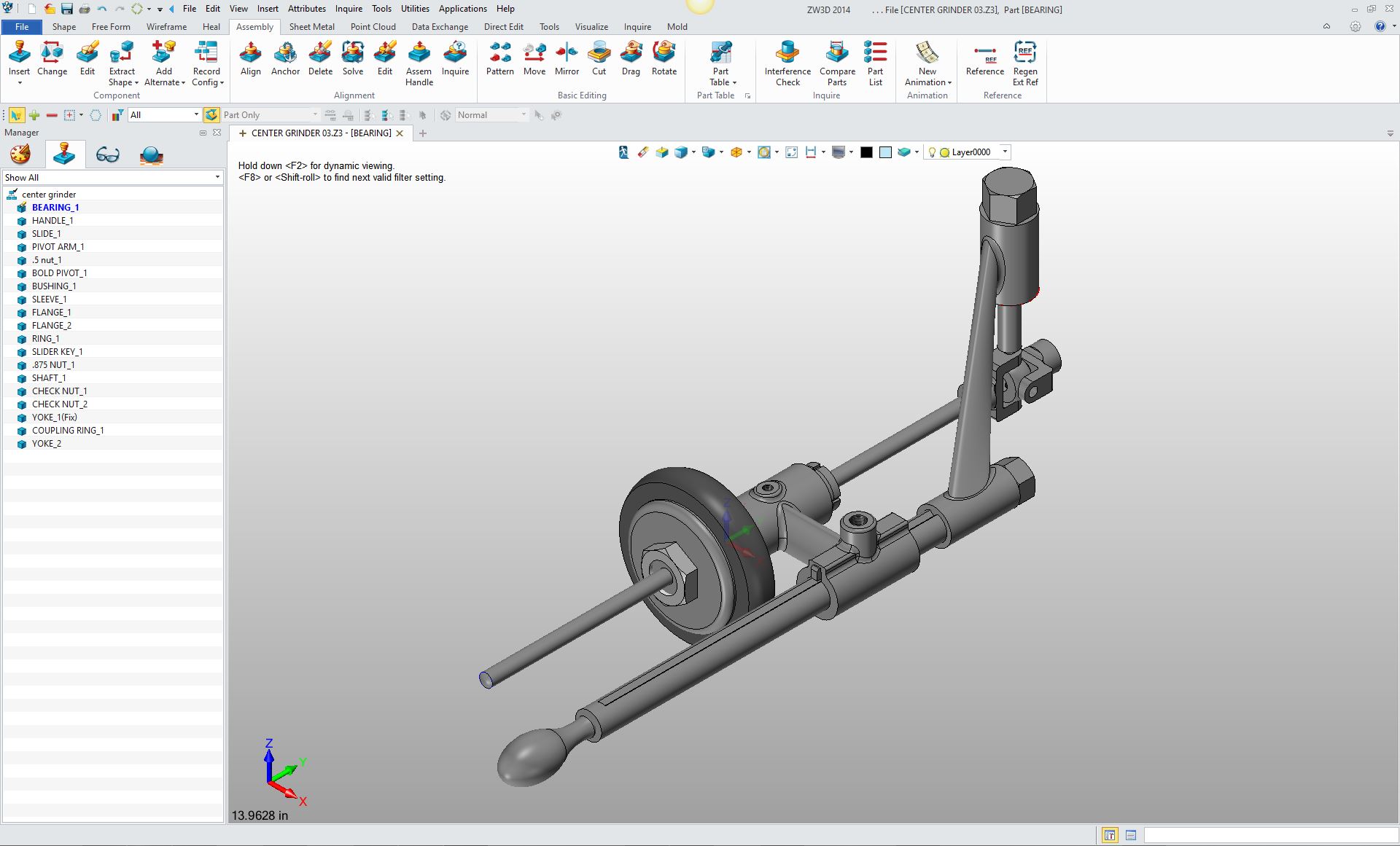 We have opened up a Multi-Object file. ZW3D allows you to do the complete project: Parts, assemblies and drawings in one file. ZW3D offers easy to use top down or in context design. Here is our blank assembly. On the left is the top assembly "Center grinder" defined. In the center is our design construction planes. One by one we start adding our parts. 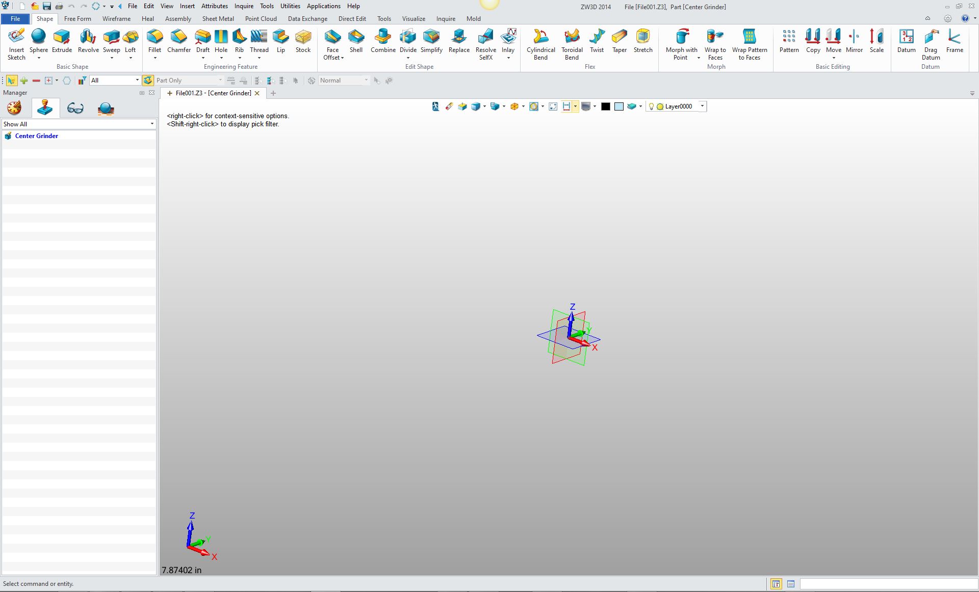 The Plane: The first thing you need to completely understand is planes. They are an intricate part of the sketch based programs. They set up what function you are going to use to create your model. Extrude, spin, sweep or loft are all based on the sketch. Once you master planes, you are on your way to learning CAD. I have done some lessons on how to do this assembly in ZW3D. This is the first lesson. 3D Modeling Techniques ZW3D Lesson One Download a fully functional ZW3D for a 30 day free trial and give it a try EXTRUDE I would say that 80% of solid modeling is done with the extrude command. If you are creating parts from sample drawings you should start with the parts that are only made up of extrusions until you feel comfortable with the system. You can look on-line for drawings. Start with easy to complex. If you need some sample drawings, you find a wide variety of part and assembly drawings that shows ZW3D and IronCAD comparisons with all of the major and not so major product that turned in to a study in 3D modeling Techniques. 3D Modeling Techniques Defined We will start with the bearing, it is completely made up of extrusions. Below is a wireframe view showing the sketches that make up the part. It is very important to create the features in a certain order putting the holes in last. 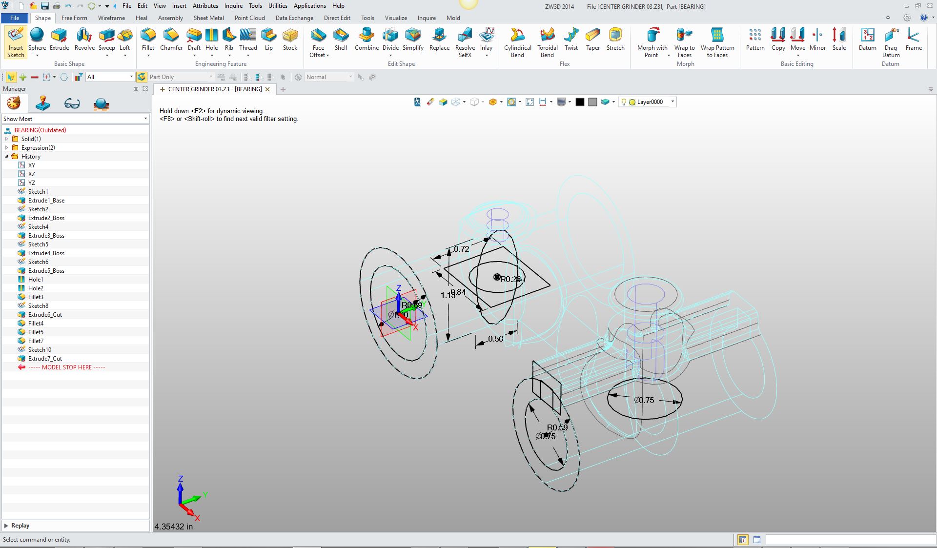 Here is a view of the finished rendered part. Blends should be added last. 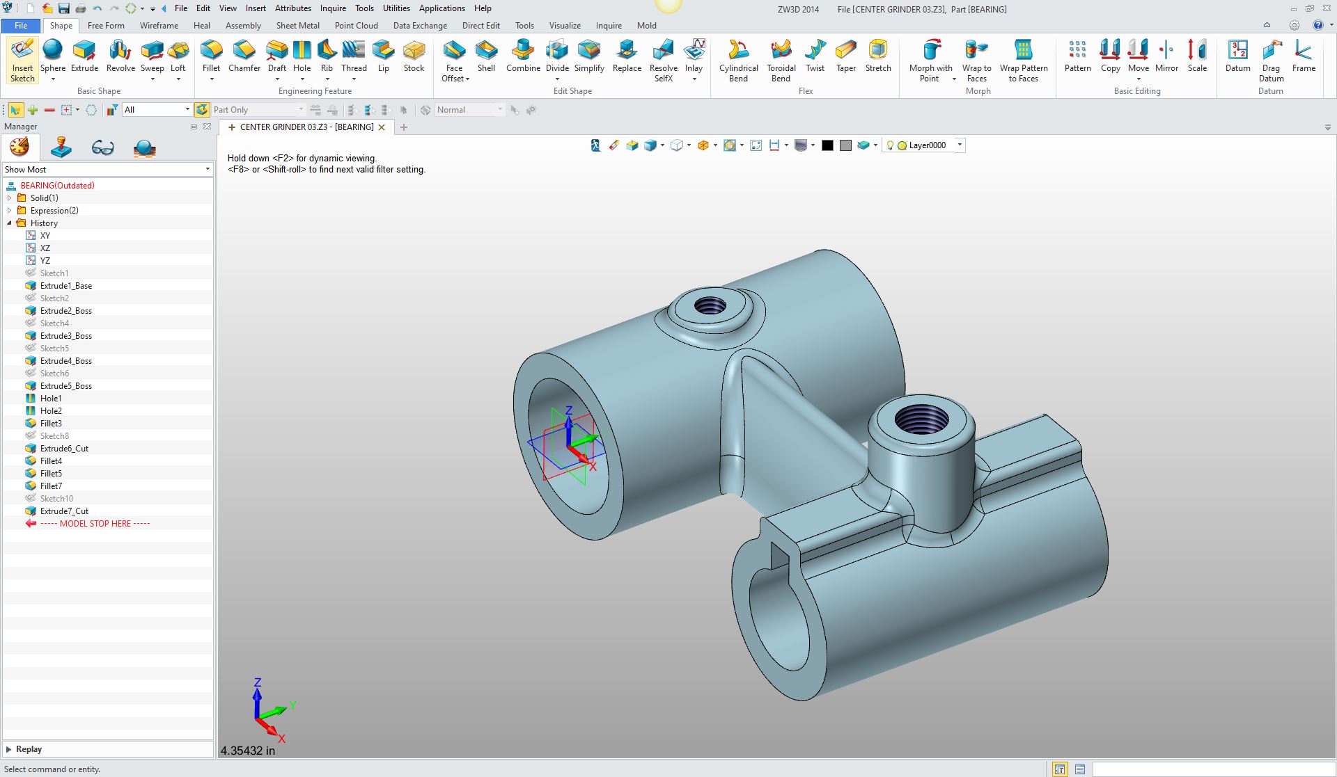 REVOLVE OR SPIN Let's move to the next most commonly used function: the Revolve or Spin. This is the next most popular design tool in all CAD packages and is probably used 15% of the time. There are two parts in this assembly that use this command. Here is the handle. You can see the sketch features. It is not so straight forward. These folks love to use ellipses. I was guessing a bit here. The cylinder on the end was done with an extrusion. 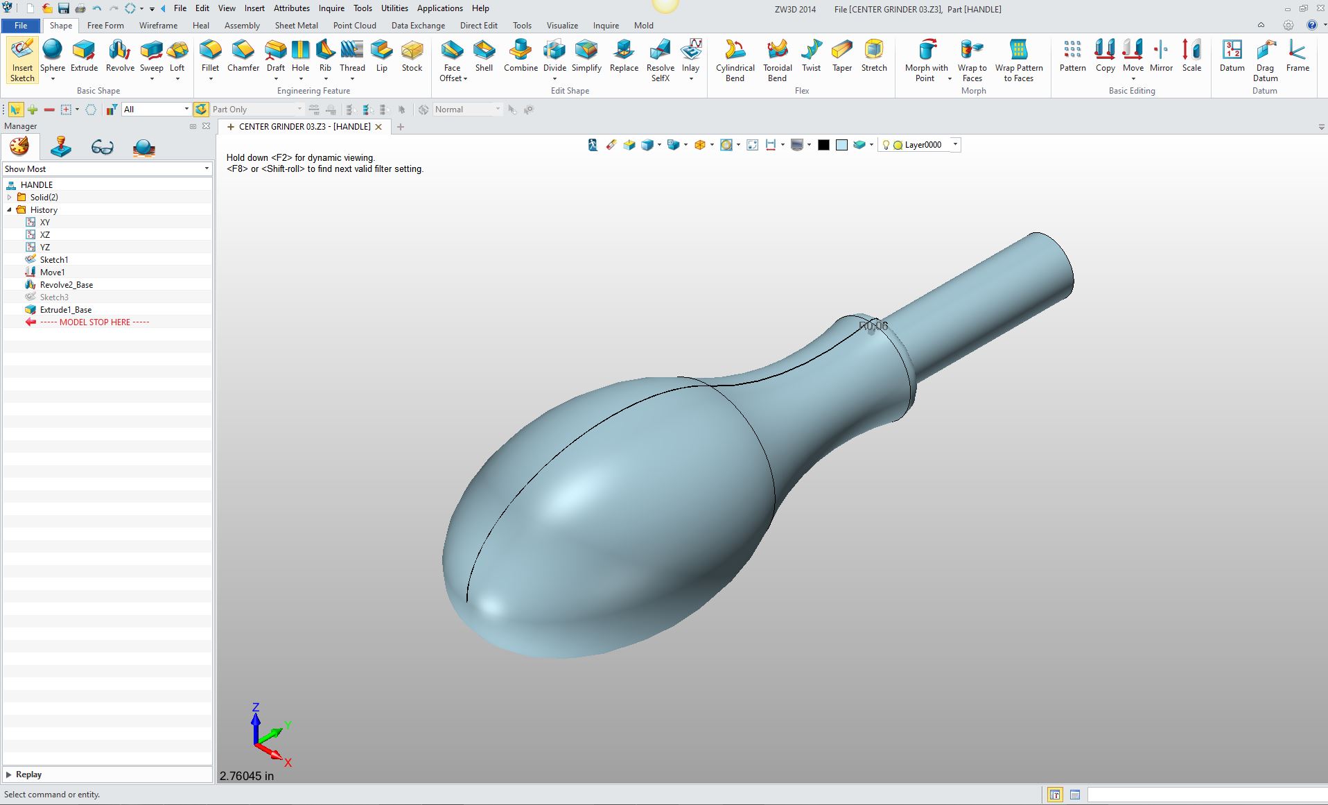 The flange is also created with the revolve tool. You can see the sketch from which it was created. I added the blend on the side later. I rarely include a blend in the sketch. They are much easier to edit if put in later. 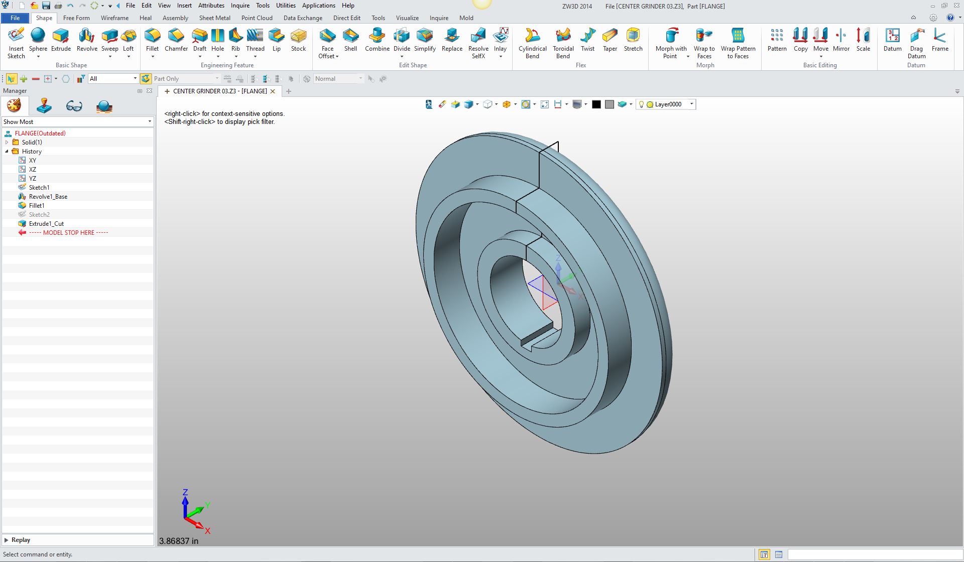 PRIMITIVE SHAPES Many of the systems only have sketching and no primitive shapes. ZW3D offers 5 basic primitive shapes: The Sphere, the Block, the Cylinder, the Cone and the Ellipsoid. You can use these through out the design process. This coupling ring was interesting. I pulled a sphere from the primitive shapes and just cut the sides as shown in the sketch. I am not really used to designing in sketches. I mostly use IronCAD with Drag and Drop Shapes from Standard or Custom Catalogs. I am sure there may be better ways to design in the Pro/e sketch, sketch, constrain, constrain paradigm. I will get better as I get into more design with ZW3D. 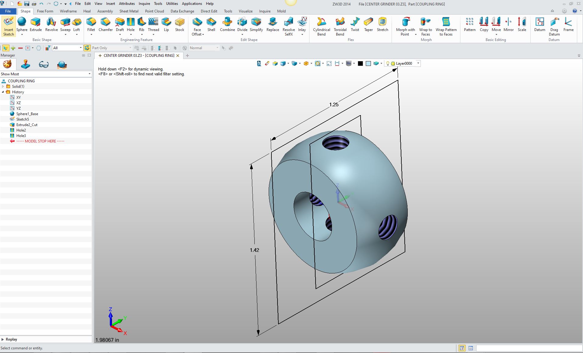 Now in the bearing and coupling ring you can see that we also used the hole tool. All CAD packages come with custom and standard hole tools. They are very easy to use. SURFACING There is another Design Paradigm besides solid modeling. Below we ran into a situation that required Surfacing. Surfacing may or may not be included in your 3D CAD system. So this part may not be able to be made with your system. But feel free to download ZW3D. Below is the pivot arm. It is made up of two cylinders attach by a twisted ellipse. I was hoping to do this in ZW3D Lite, but the twisted ellipse forced me to use ZW3D Standard to put the arm in as a ruled surface. ZW3D Standard has full free form Class-A Surfacing. Now I assumed this was the intent of the designer. I showed this to a pattern maker from the days before 3D CAD and he said no problem. On the left you see the steps that make up this part. You can see I have stopped the program at the two extruded cylinders with the elliptical holes. 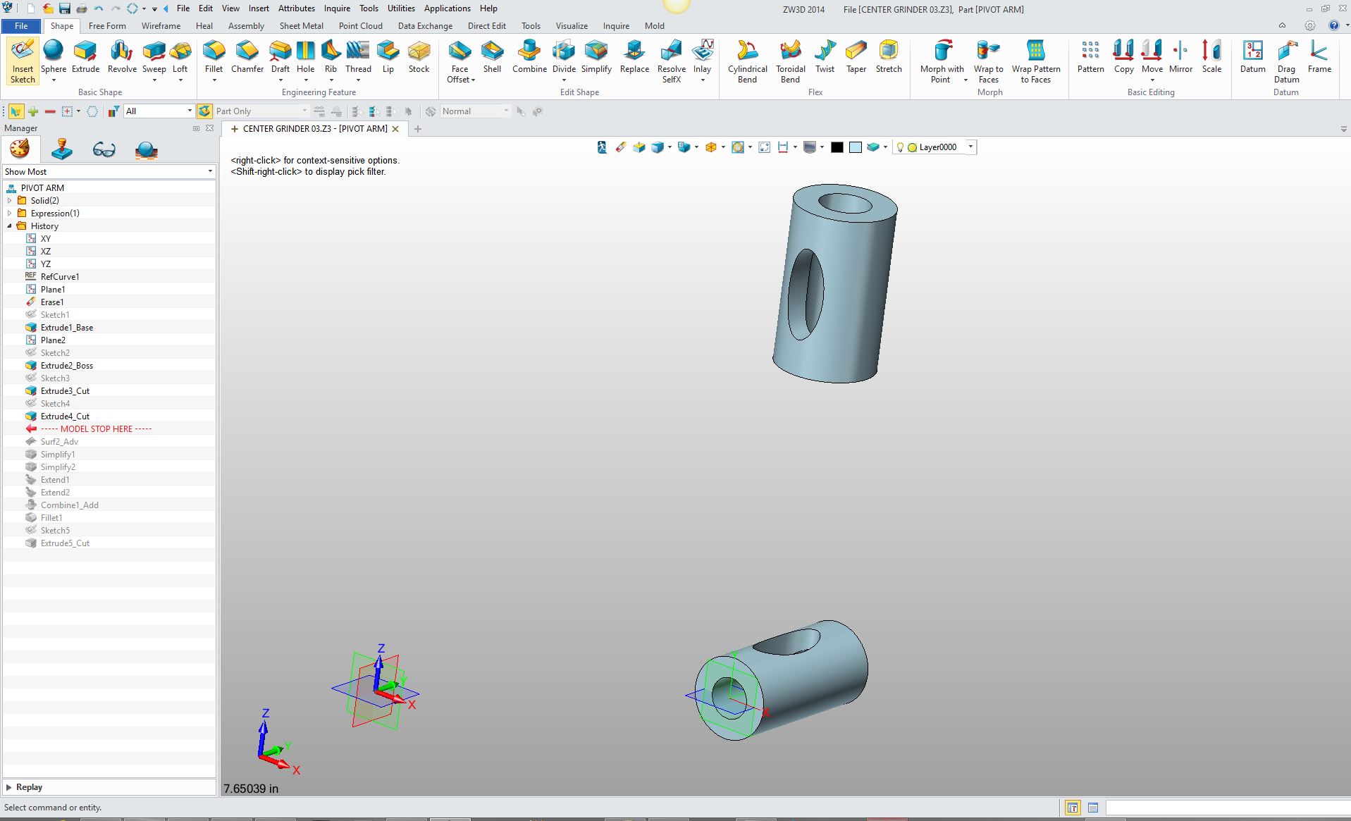 Here is the ruled surface utilizing the edges of the ellipses. I added the blends after combining the surface with the cylinders. ZW3D automatically made it a solid. 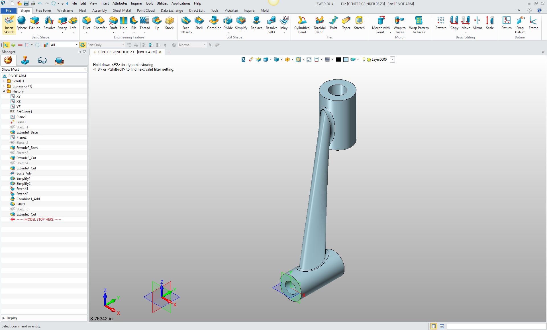 But I was left with these holes. The ruled surface was tied to the edges of these holes so I couldn't delete them, I could have limited the depth, but ZW3D has direct edit and the simplify function actually allowed me to remove the holes in both cylinders. 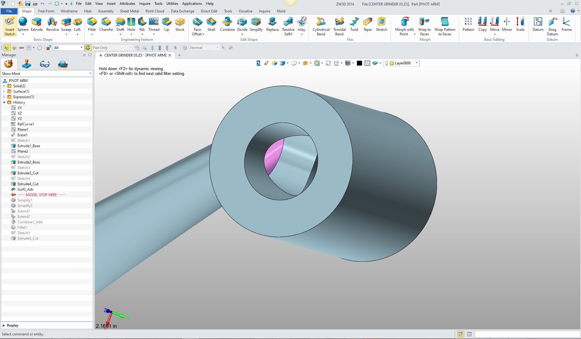 Here are the holes removed and the simplify modification step is in the history. This shows how you can use direct edit functionality as part of your design process. 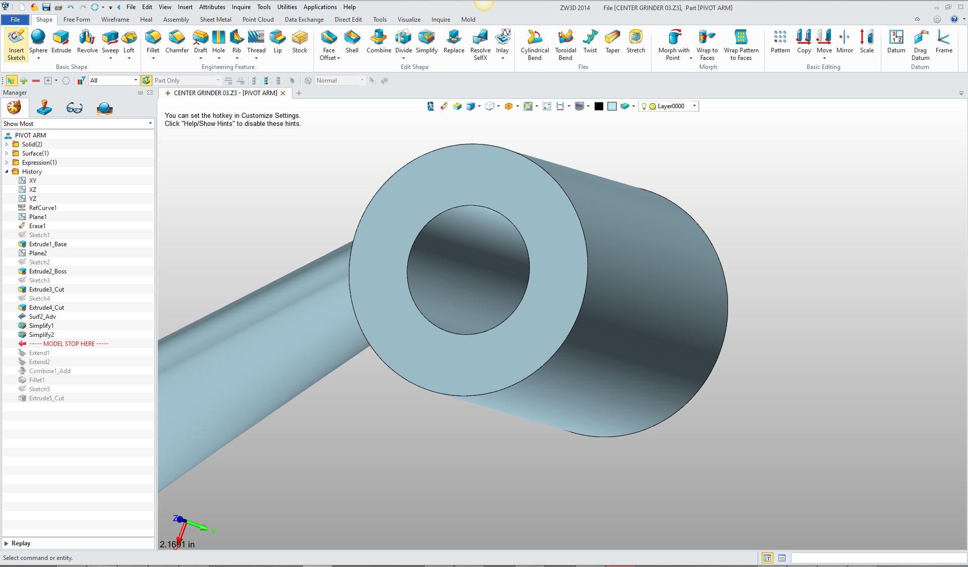 Much of this design was creating planes in different locations to create our parts or even creating them at the assembly origin and moving them into place. I am not really up to speed on the best practices of the Pro/e design paradigm and probably could use some tips. In IronCAD, the plane is not an independent feature so this is a bit new to me. You just design in one space and all the parts freely coexist. So when you learn a system with the Pro/e paradigm you should understand the following: Planes extrude Spin or Revolve. Once you have mastered these you can take on the formidable Sweep and Loft. AID (Associated Information Document) Ref: The Death of the Drawing We may have to make AID's. Here are a few AID's that are included in the part. ZW3D is a bit different than other 3D CAD programs since the AID is an integrated part of the assembly or part. So you do not have to maintain separate files. PMI (Product Manufacturing Information) vs AID (Associated Information Document) The Bearing 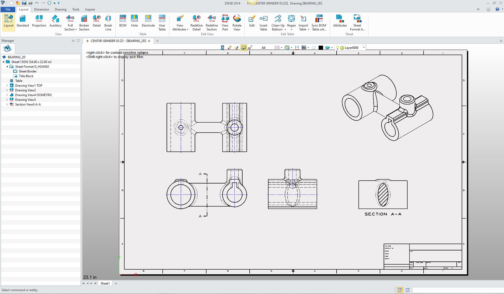 Here is the assembly, notice there are two sheets. You can select the sheet you want by the selecting the tabs at the bottom. Assembly Sheet One. 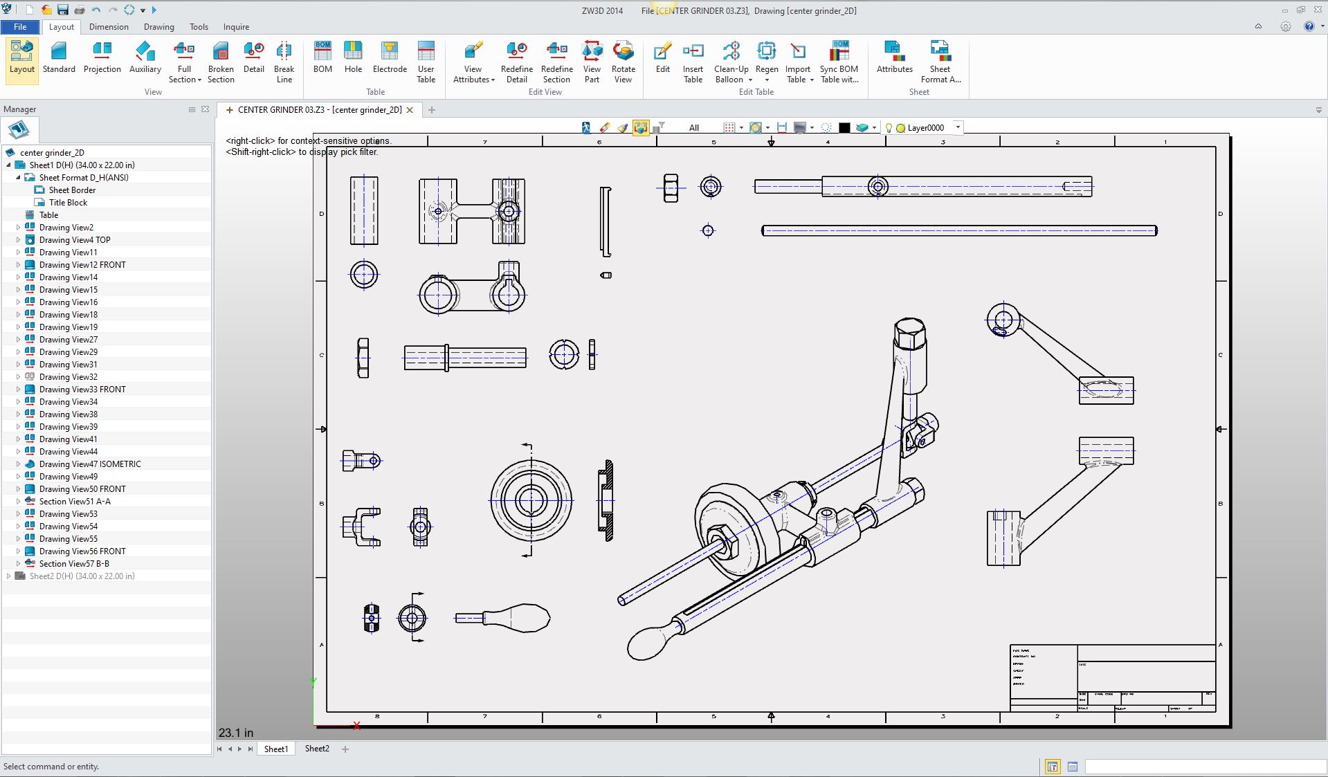 Assembly sheet two 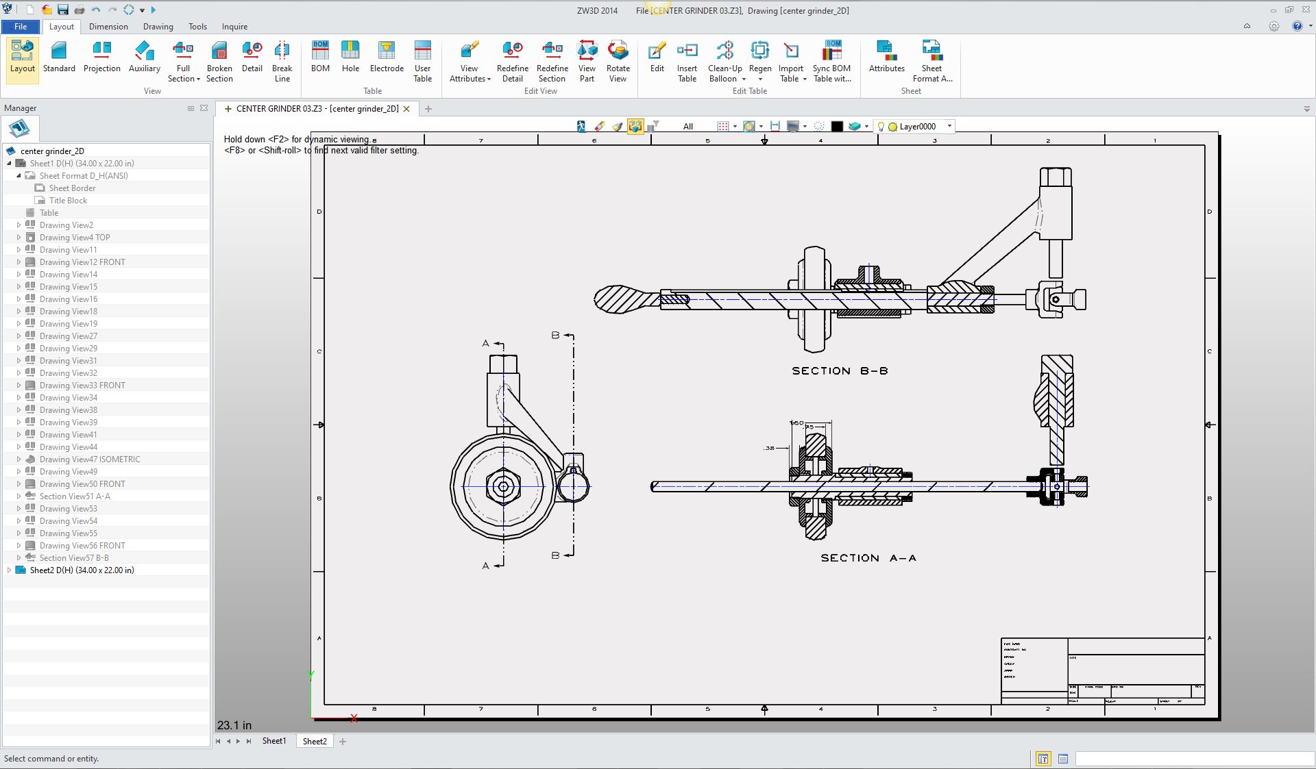 In this part there was no need to use the sweep or loft function. They are rarely used so they may take a new learning curve each time you need to use them. Now, I know there are a few of you that have designs that require extensive use of these functions. But most rarely use them. I would do any sample drawings or AID's that required the these functions last. Of course, there is nothing wrong with getting proficient with any of the standard or unique functions many of the 3D CAD systems offer. Most of you that are familiar with the Pro/e paradigm could easily get up to speed with ZW3D in a few hours of play. Most 3D CAD systems are priced out of the range of most of us. But you can have a fully professional system at a third of the price of SW or any of the other Mid-range 3D CAD system. ZW3D has some very flexible rental rates that make it easy to get into professional 3D MCAD starting at a 6 month rental of $450.00 ZW3D Pricing
Happy Modeling!!
We sell and support IronCAD
and ZW3D Products and provide engineering services throughout the USA and Canada!
If you are interested in adding professional hybrid modeling capabilities or looking for a new solution to increase your productivity, take some time to download a fully functional 30 day evaluation and play with these packages. Feel free to give me a call if you have any questions or would like an on-line presentation. |