3D Modeling Techniques IRONCAD vs Solidworks Lesson One
Streamlined Sketching/Feature Based Modeling
When I introduce IronCAD's very
flexible design paradigm I have a hard time to get the Pro/e clone
users, like Solidworks and other programs, to understand the drag and
drop design paradigm.
Download IronCAD/Inovate and
take the one day and 17 lesson course. I get rave reviews from my
new customers. Give it a try, this is a fully functional 30 day
evaluation with all of the native translators so you have access to
your legacy engineering information.
I saw some Fusion 360 exercises online and I decided to compare
IronCAD. It quickly turned into a study in modeling techniques. I have created
many comparisons to Fusion 360, Onshape, Solid Edge, NX, Creo,
Catia and Inventor
lessons to show the difference between
IronCAD and my modeling techniques. I found the presenters working
identically wasting massive amounts of time
with overly complex constrained sketching procedures. I was so unimpressed that
I decided to model the parts or assemblies showing my modeling techniques plus IronCAD's superb design system.
3D Modeling Techniques Defined
Many of these modeling techniques can easily be implemented even
within their existing system. I call it Streamlined Sketching and
Feature Based Modeling. Please review a few of the above IronCAD
comparison lessons, there are some very stark differences.
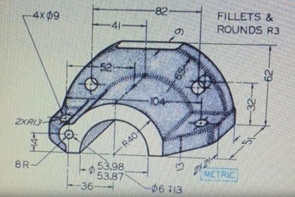
Here is the drawing if you would like to
give it a try.
While creating 3D models from drawing is the very best
way to learn 3D CAD and maybe some design techniques it does not
expose the designer to the design flexibility necessary in design. IronCAD is all top down due to the single model environment.
Creating mating parts is a cruise. But modeling is just one aspect of a
well designed productive 3D CAD system.
Solidworks
is a marginal 3D CAD system based on the dated Pro/e (Creo) history
based modeling system. I have sold this product years ago and found
it, like all of the other Solidworks clones, not productive enough
for our engineering department. We use what we sell. That gives us
the experience to effectively support our user base.
I would do a
video, but I really am not good at it. So I will show you step by
step. I will try and get IronCAD support to create one. They are
very good.
As with my Ironcad vs Fusion 360 exercises
I have found the same problems with Solidworks and the other major
systems. The modeling
technique is hugely responsible for the level of productivity. Those
of you that are only trained in the complex and time consuming
constrained sketching world are truly limited by not using the freedom of
Streamlined Sketching and Feature Based Modeling, that is available in even the most Solidworks-ish of CAD systems. If your
designers are designing in these very unproductive and time
consuming processes it might be time to review your standard design
processes. Don't have any do you?
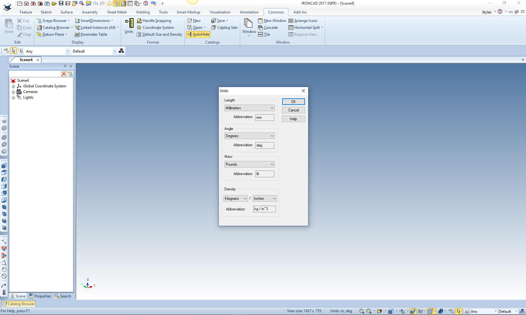
Here is IronCAD. My default is inches,
so we will set the units to mm. Let's get started.
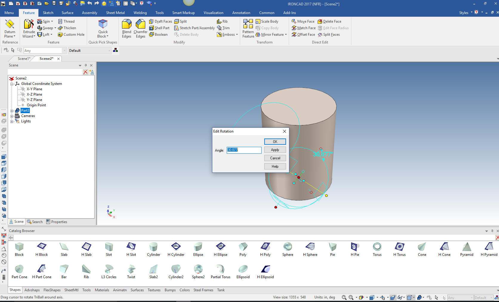
I drag
and drop the a cylinder into the scene at X0Y0Z0 and size it. Look at how
much, just this one step saves design time. We will need to rotate
with the tribal to move it to the correct orientation.
Why does IronCAD
call it a scene instead of a workspace? IronCAD was first released
as a graphic design program called Trispectives. It still has much
of the graphic design functionality. It truly is a wonderful mixture
of professional 3D CAD and graphic design, which puts it in a much
more flexible category as compared to the Solidworks clones.
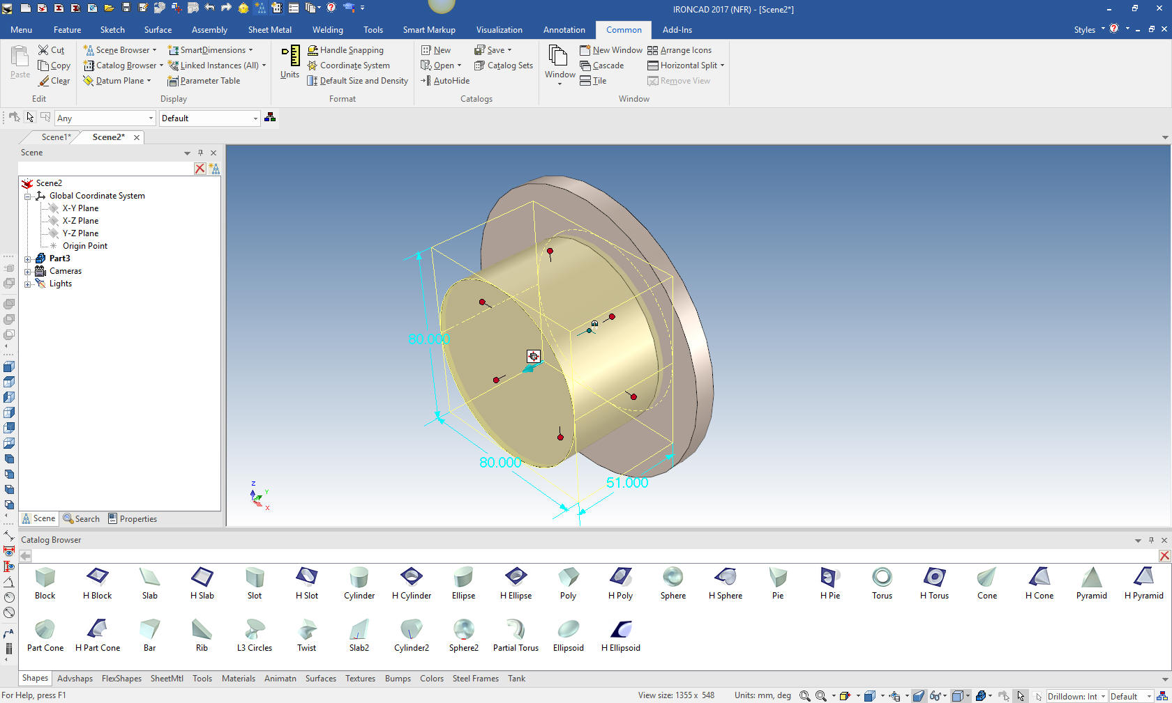
Once rotated we
size it and drag and drop another cylinder to center of the face.
We pull the farside length handle and by holding down the shift
key we can snap it to the opposite face of the existing cylinder,
that way we can work directly with the dimensions. We now size the
cylinder 80 X 51.
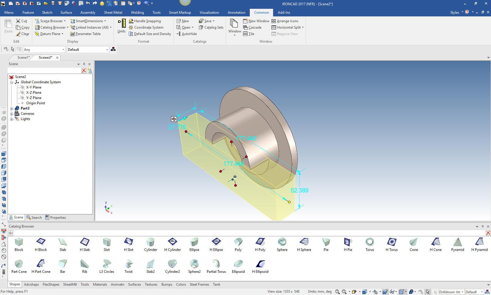
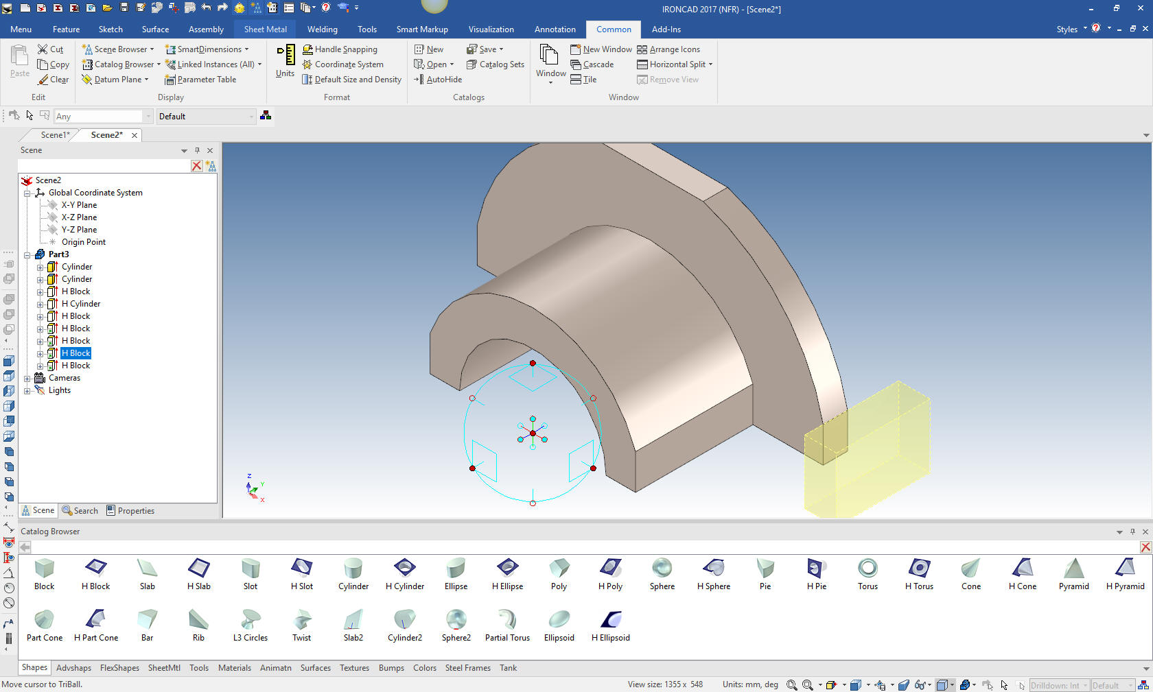
We
drag and drop a hole cylinder to the center of the smaller cylinder
face and size it. Now I will drag and drop a hole block on to the
same face and size it. I take the top handle and snap it to the
center of the hole then pull it into a shape that removes the bottom
of the overall shape. I have left it partially done to show how it
works.
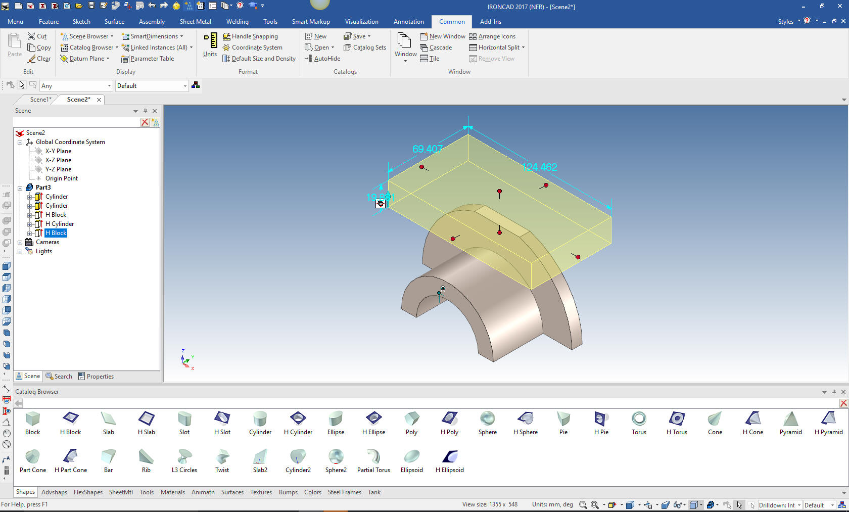
Now we
drag and drop a hole block on the bottom face and size it. The
reason we drop it on the bottom face is that it is a better
reference point. You start thinking in a different way with this
modeling paradigm.
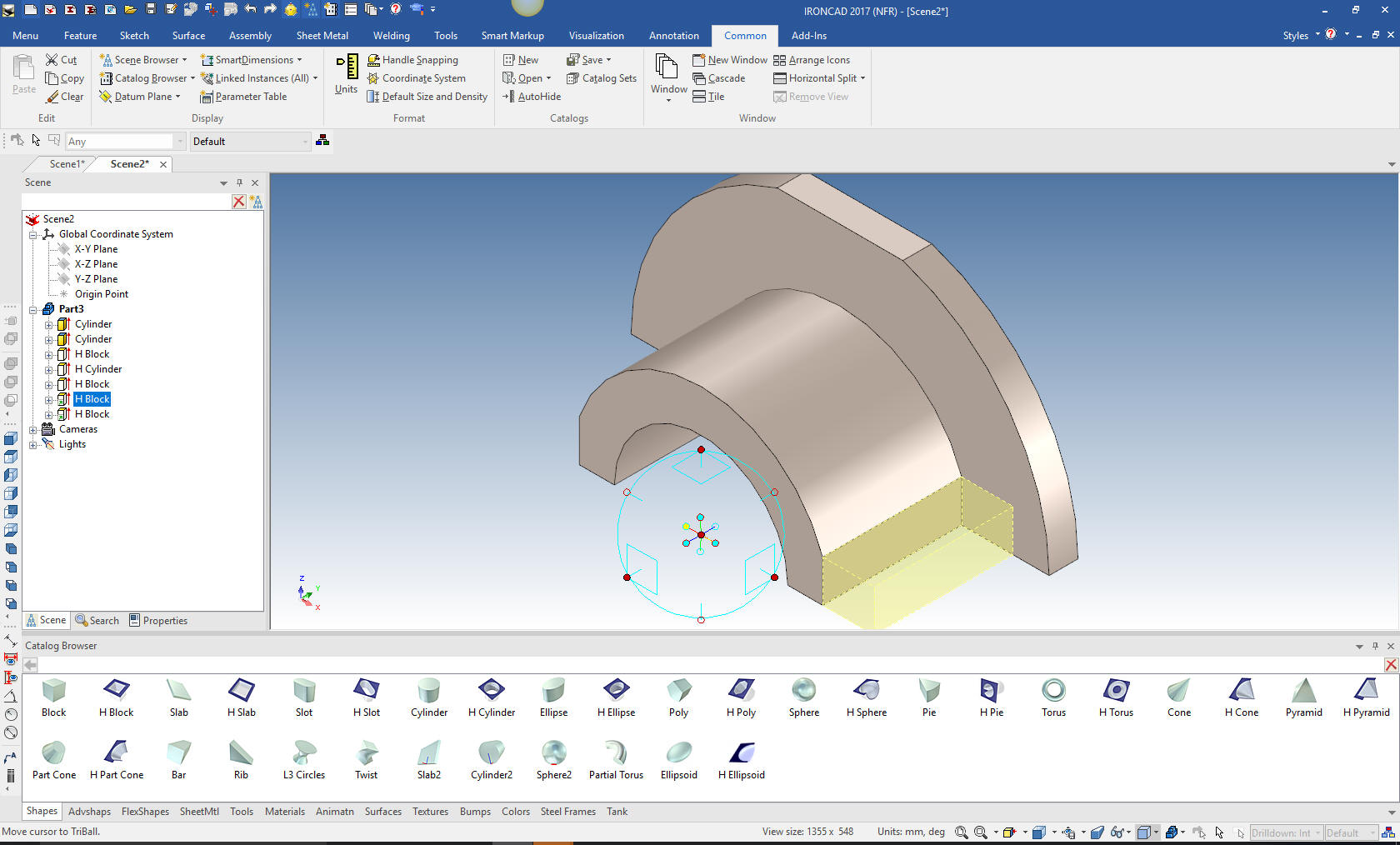
We
drag and drop another hole block on the front face and size it. Then
by relocating the triball to the center of the hole we mirror and
link it.
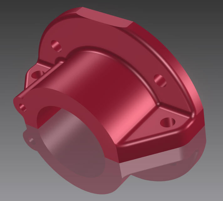
After
looking at the part I thought I would do the same trim to the outer
edges, just seems logical.
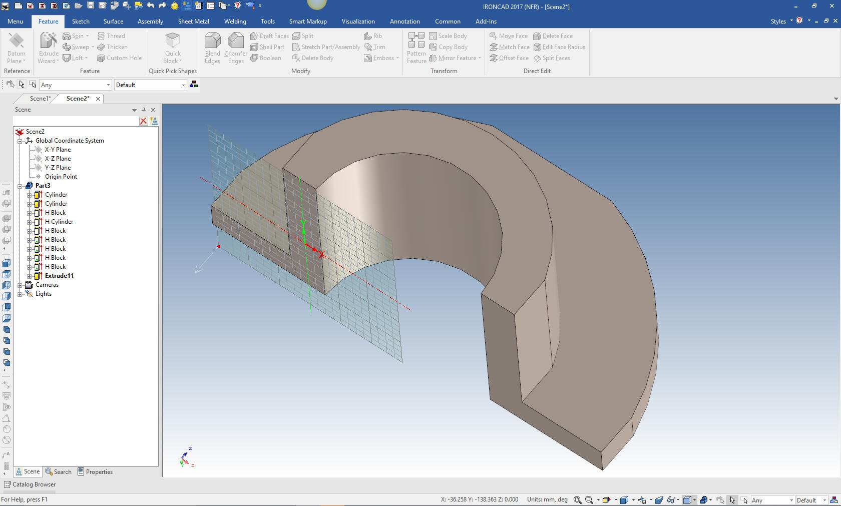
Yes, we can sketch when we have to. I select the Extrude Wizard and
place it on the bottom face. The Extrude Wizard is by far one of the
most used functions for designing in IronCAD. I will select add
material and it will put a sketching plane on that face.
Note: Since we are done with drag and drop, we set the catalog to
auto hide to increase the size of our work space. I only have the
catalog shown for presentation usually you work with it auto hidden.
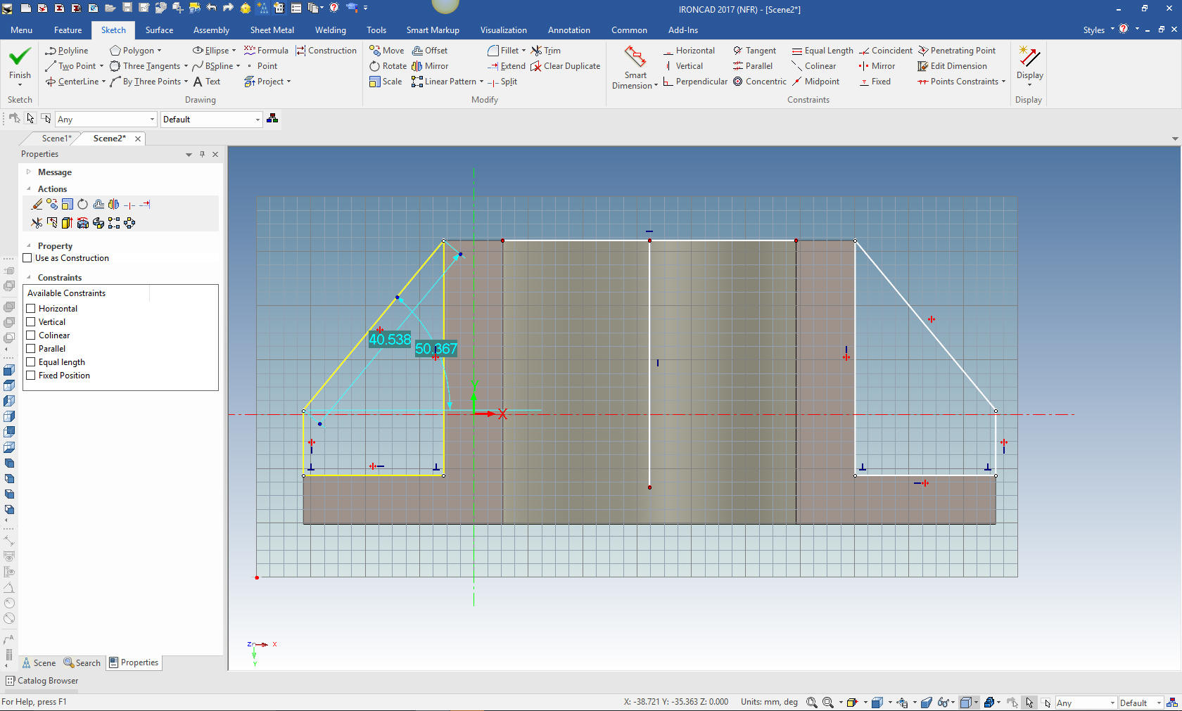
I will look directly into the plane and start sketching the
profile. I will project the effected edges. We can edit the line
directly, so there is no need to drop on a constrain dimension.
Basically it is nothing more than connecting the dots. We project
the edge of the hole and add a vertical line for mirroring. We
will mirror the sketch, delete the construction lines and we are
done. It then is automatically extruded.
Note: IronCAD has a
standalone sketch that you use for sketching where you do not want
an instant extrusion. Also it used to import 2D graphics in the form
of dxf. Besides the extrude wizard we also have spin, sweep and loft
wizards.
Note: If you drag a selection rectangle to the right
it will only select the entities inside the rectangle, if you drag
left you select the entities inside and those they cross. A very
handy feature. Just one of the many that IronCAD has implement to
speed up the design process. There is no CAD system faster or more
fun to design in than IronCAD or its modeling only package, Inovate.
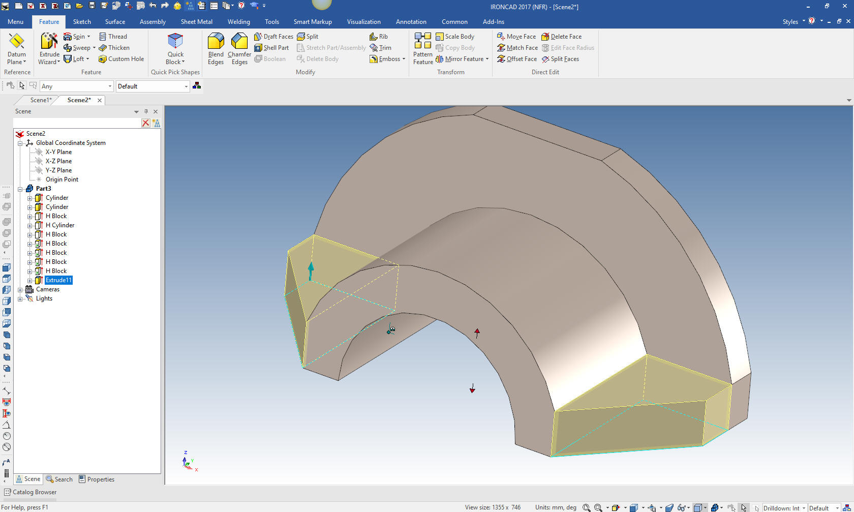
We
just pull the extrusion with the shift key selected to the
intersection point or just input 13mm. You usually use the pull to
point as you do your design.
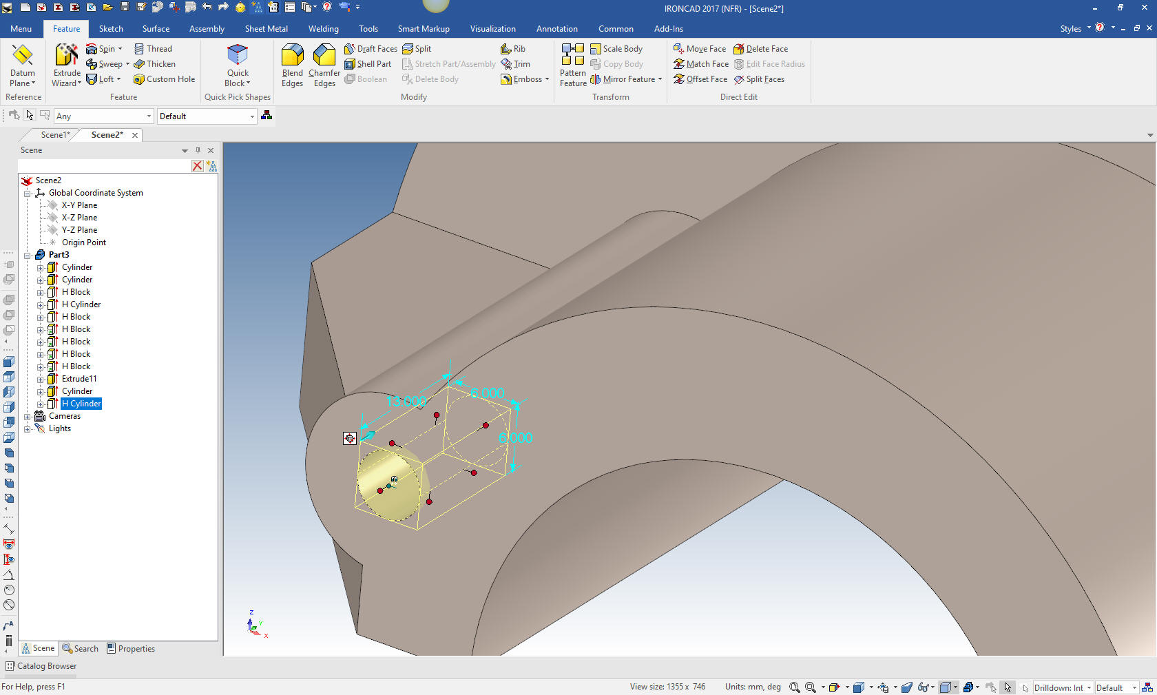
Now
for the boss. We just drag a cylinder on to the near face and size
it. We then locate it from the center of the hole with the triball.
We just drag and drop a hole cylinder
to the center of the new boss and size it.
Note: When
drag and dropping, IronCAD recognizes centers, mid points and ends
to place your features, parts or assemblies. This is an incredibly
productive function when designing.
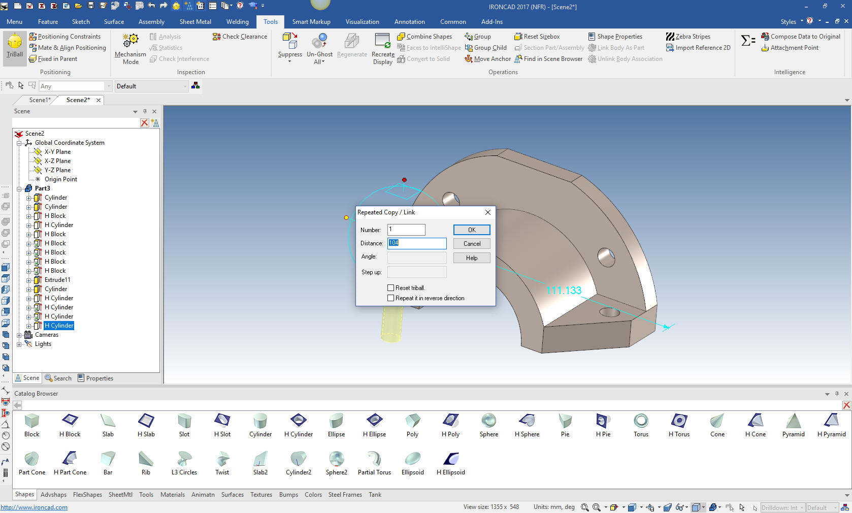
We
will do the same with the next four holes.
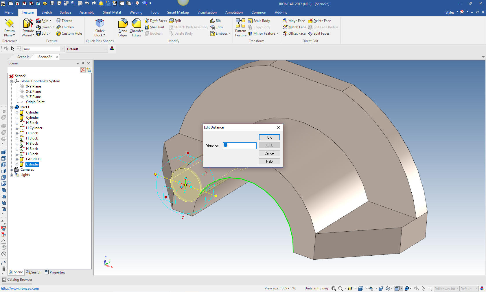
We drag and drop
the to the affected face and size and locate. We use the triball to
link the other side. We can pull it, set the distance and link it.
Note: You can move, copy, link or pattern with the triball.
Now we are ready for the blends. As I experienced with the Fusion
360 presenter I have also found with the Solidworks fellow. What do
they have against putting in blends instead of sketching them. For
the life of me I cannot understand why they do it. I believe those
that teach have never designed and are basically a bunch of 3D CAD
jockey's.
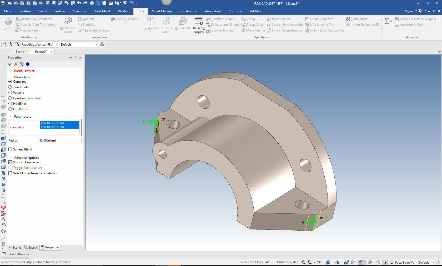
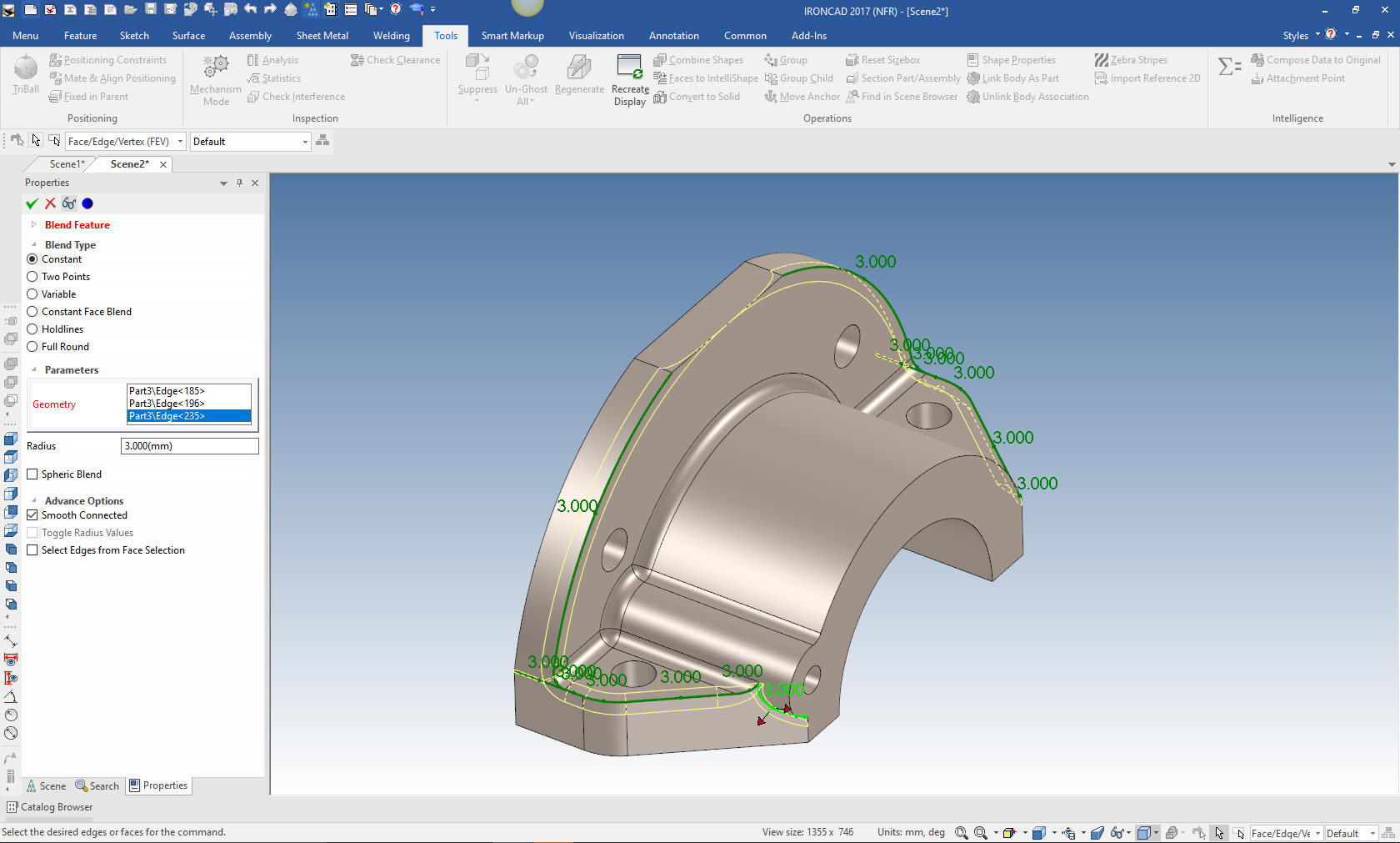
I will first put in the 13mm blends. The
Solidworks presenter missed one of these. I also notice he had to
keep going back to an icon to select blend. IronCAD lets you select
the edge, right click and select blend or chamfer.
Note:
IronCAD allows different selecting with the left mouse button, first
is the assembly (yellow), then part (blue), then feature (yellow)
then edge or face (green).
IronCAD is a much different, more
productive way of modeling. But that is just one of the highly
productive features that makes this system 5X faster with conceptual
design and 10X with modifications.
Now we add the rest of the blends. I have notice the 3D CAD jockeys
just start putting in the blends. You can see this as the Solidworks
fellow struggles. It is not Solidworks, it is that you have to be
selective in the way you put them in. I put in the three that go
along cylinder then the one against the face of the large cylinder,
the then the rest in three separate steps. Nothing makes you look
more like an amateur than poorly places blends.
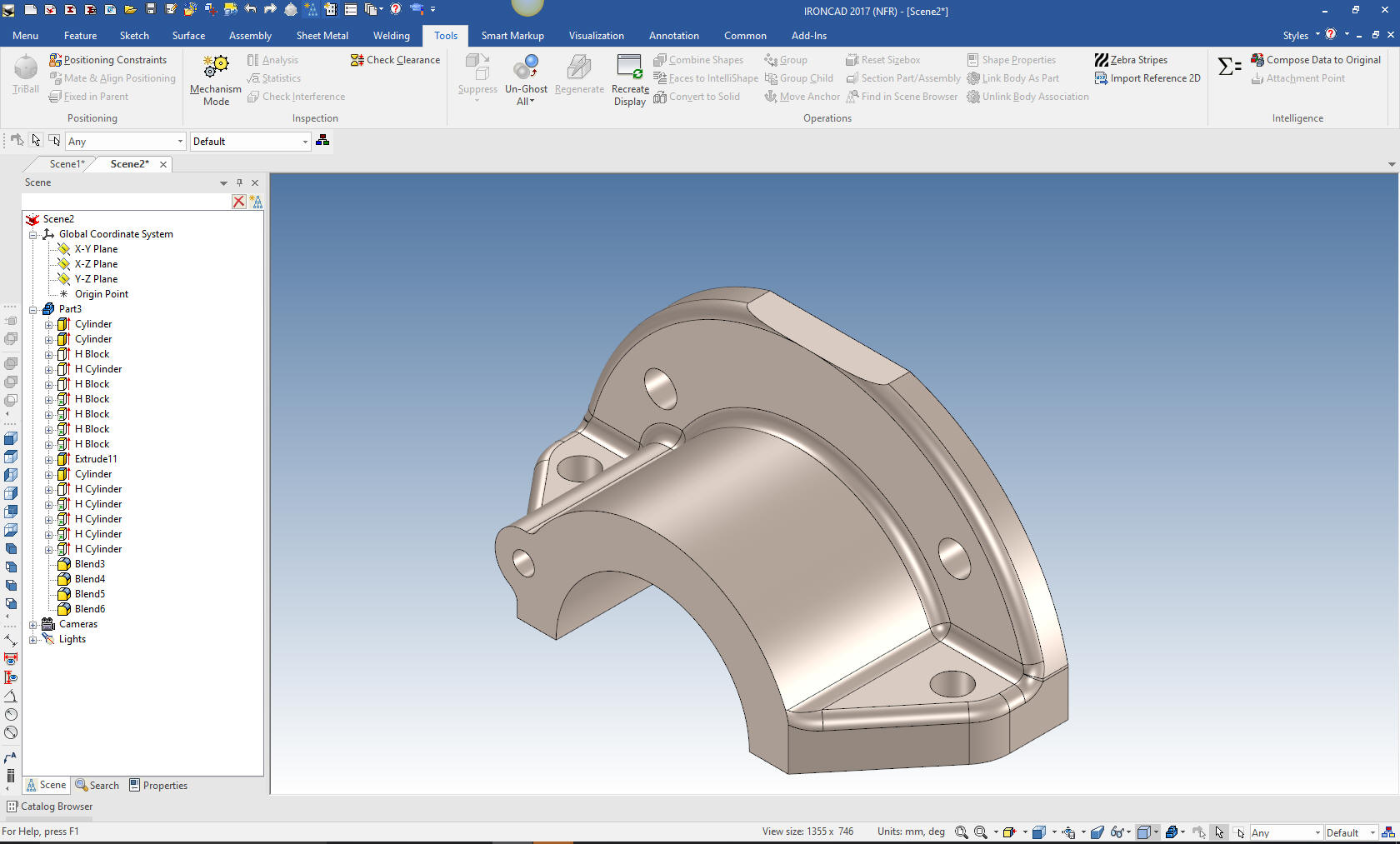
We are done with the part before the
Solidworks fellow is done with half of his sketches. Also I find
IronCAD offers a more disciplined design process.
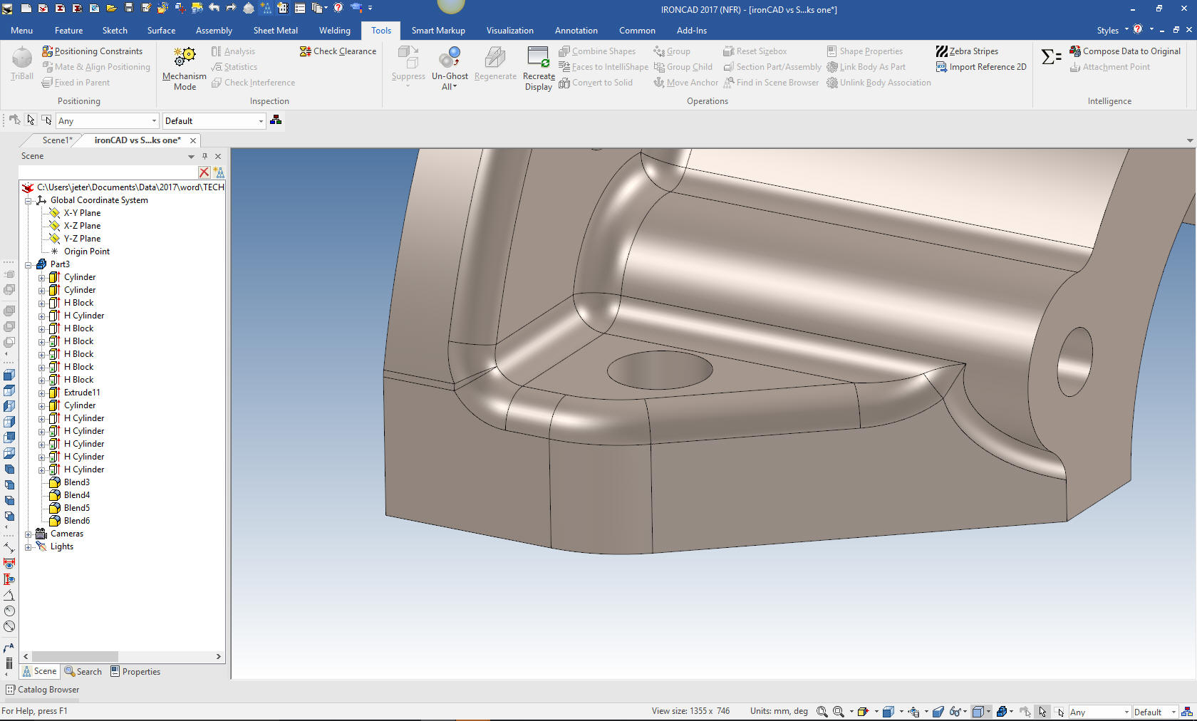
I checked the part again and I
want to show you more on blending. I made a bit of a mistake. As I
looked at the blends I found this.
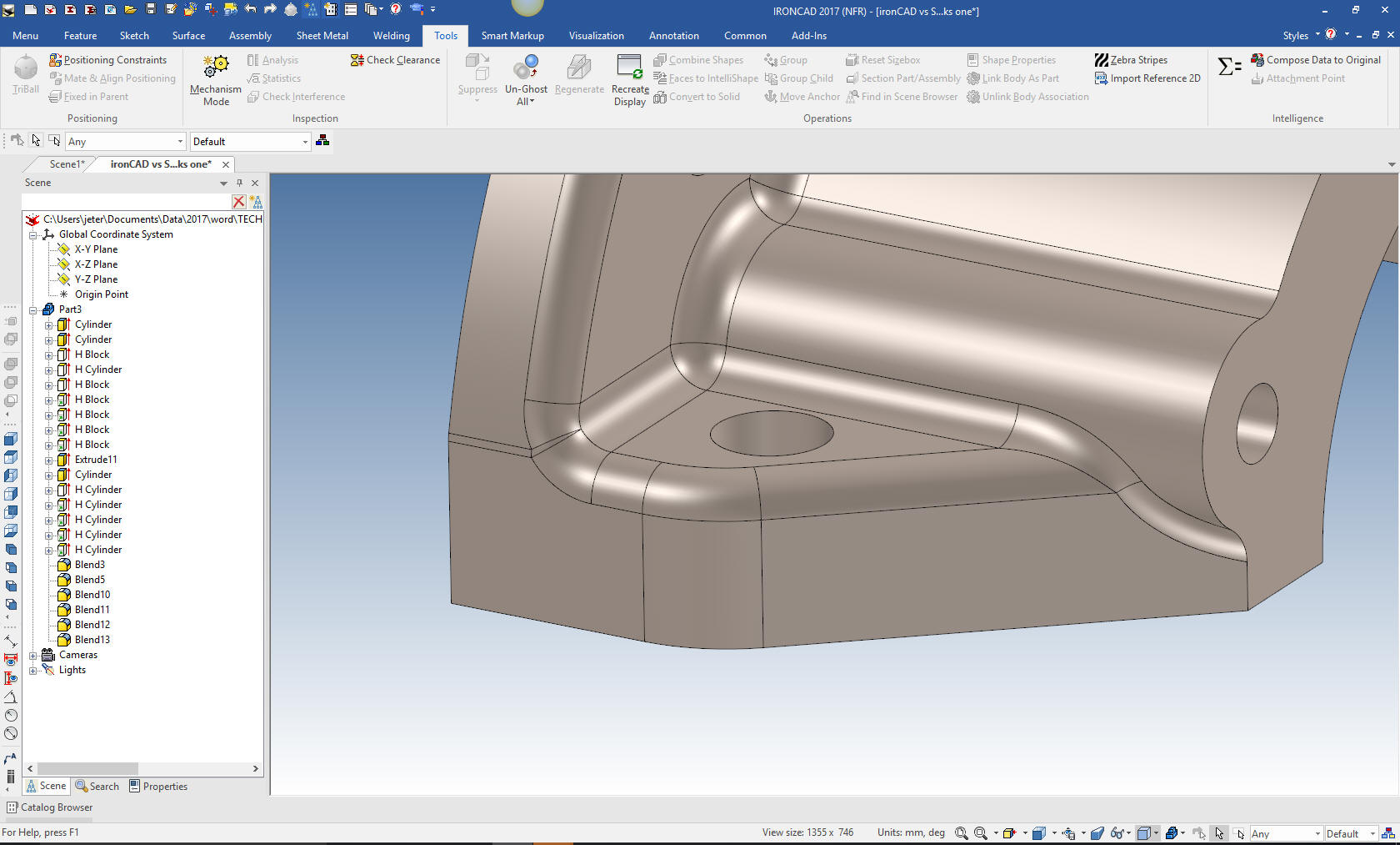
I revised the order of the blends and I
came up with the correct blend here and on the otherside. It is easy
to overlook proper blending.
Give me a call if you have any
questions. I can set up a skype or go to meeting to show this part
or answer any of your questions on the operation of IronCAD. It
truly is the very best conceptual 3D CAD system.
If you are interested in adding professional
hybrid modeling capabilities or looking for a new solution to
increase your productivity, take some time to download a fully
functional 30 day evaluation and play with these packages. Feel free
to give me a call if you have any questions or would like an on-line
presentation.