3D Modeling Techniques IRONCAD vs Solidworks Lesson
Twelve Streamlined Sketching/Feature
Based Modeling Two Similar Parts and AIDs:
Two Files
When I introduce IronCAD's very
flexible design paradigm I have a hard time to get the Pro/e clone
users, like Solidworks and other programs, to understand the drag and
drop design paradigm.
Download IronCAD/Inovate and
take the one day and 17 lesson course. I get rave reviews from my
new customers. Give it a try, this is a fully functional 30 day
evaluation with all of the native translators so you have access to
your legacy engineering information.
I saw some Fusion 360 exercises online and I decided to compare
IronCAD. It quickly turned into a study in modeling techniques. I have created
many comparisons to Fusion 360, Onshape, Solid Edge, NX, Creo,
Catia and Inventor
lessons to show the difference between
IronCAD and my modeling techniques. I found the presenters working
identically wasting massive amounts of time
with overly complex constrained sketching procedures. I was so unimpressed that
I decided to model the parts or assemblies showing my modeling techniques plus IronCAD's superb design system.
3D Modeling Techniques Defined
Many of these modeling techniques can easily be implemented even
within their existing system. I call it Streamlined Sketching and
Feature Based Modeling. Please review a few of the above IronCAD
comparison lessons, there are some very stark differences.
While creating 3D models from drawing is the very best
way to learn 3D CAD and maybe some design techniques it does not
expose the designer to the design flexibility necessary in design. IronCAD is all top down due to the single model environment.
Creating mating parts is a cruise. But modeling is just one aspect of a
well designed productive 3D CAD system.
Solidworks
is a marginal 3D CAD system based on the dated Pro/e (Creo) history
based modeling system. I have sold this product years ago and found
it, like all of the other Solidworks clones, not productive enough
for our engineering department. We use what we sell. That gives us
the experience to effectively support our user base.
I would do a
video, but I really am not good at it. So I will show you step by
step. I will try and get IronCAD support to create one. They are
very good.
As with my Ironcad vs Fusion 360 exercises
I have found the same problems with Solidworks. The modeling
technique is hugely responsible for the level of productivity. Those
of you that are only trained in the complex and time consuming
constrained sketching world are truly limited by not using the freedom of
Streamlined Sketching and Feature Based Modeling, that is available in even the most
Solidworks-ish of CAD systems. If your
designers are designing in these very unproductive and time
consuming processes it might be time to review your standard design
processes. Don't have any do you?
Let's get started!
You will see
with Streamlined Sketching and Feature Based modeling is much more
productive and flexible. It gives you a more real world feel to
your design process and is a much more pleasurable and productive experience.
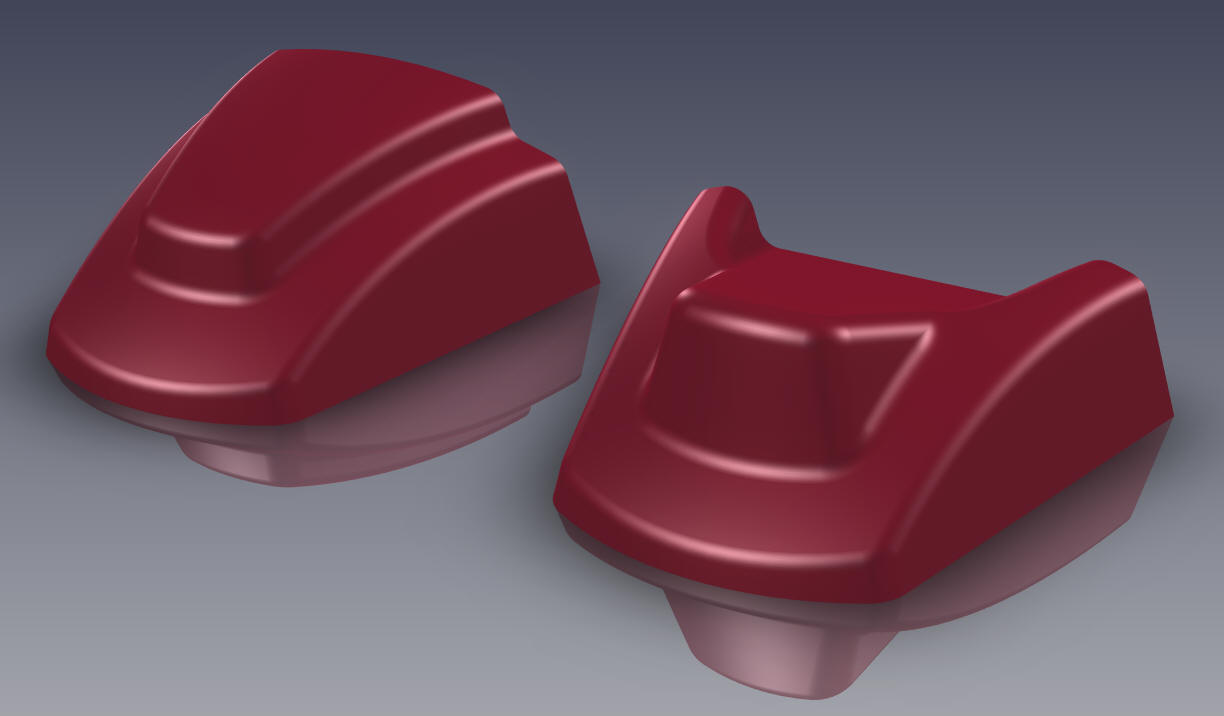
We will start with -1 Cover
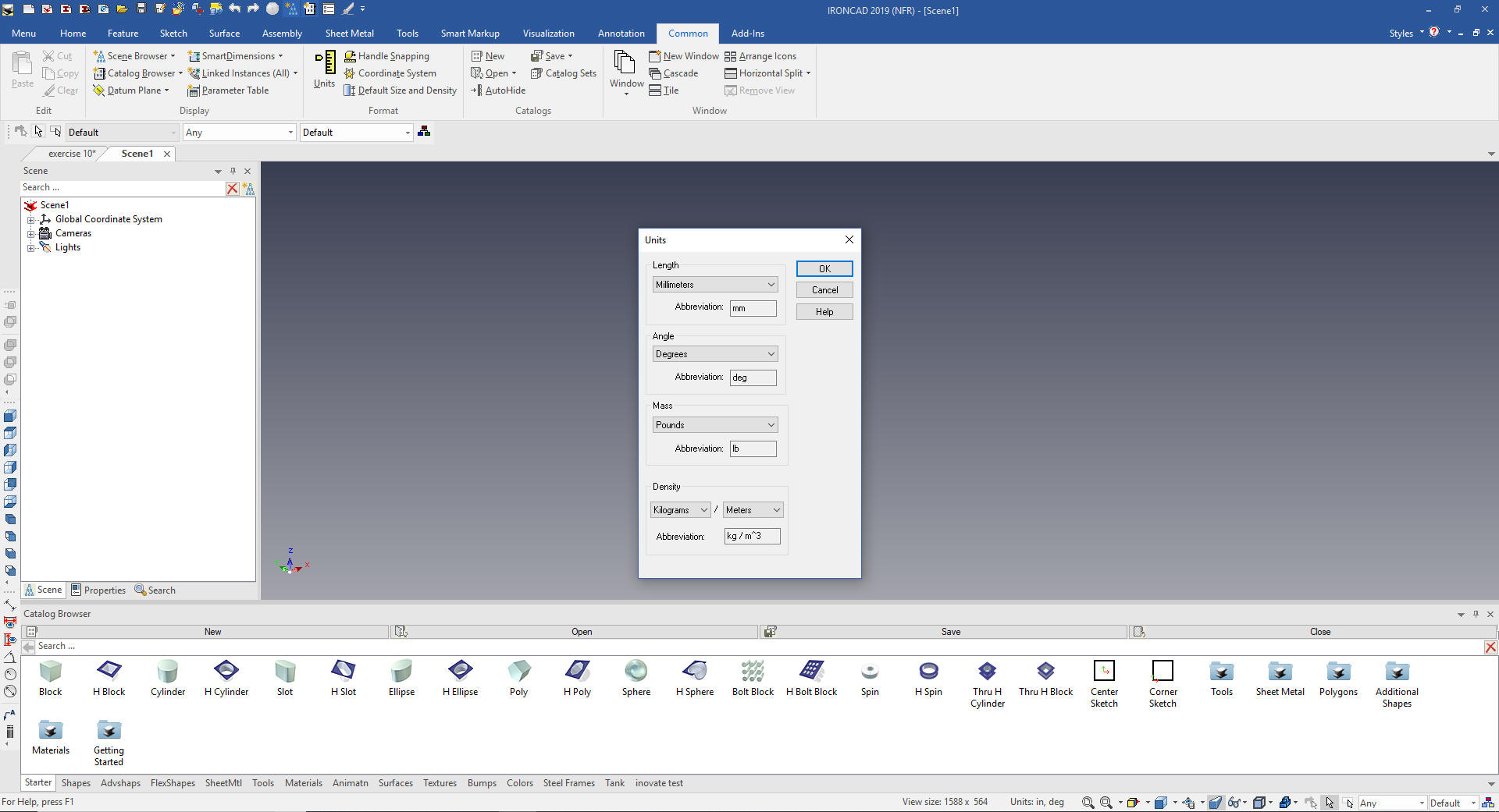
We set the units to mm
This is going to be a fun exercise.
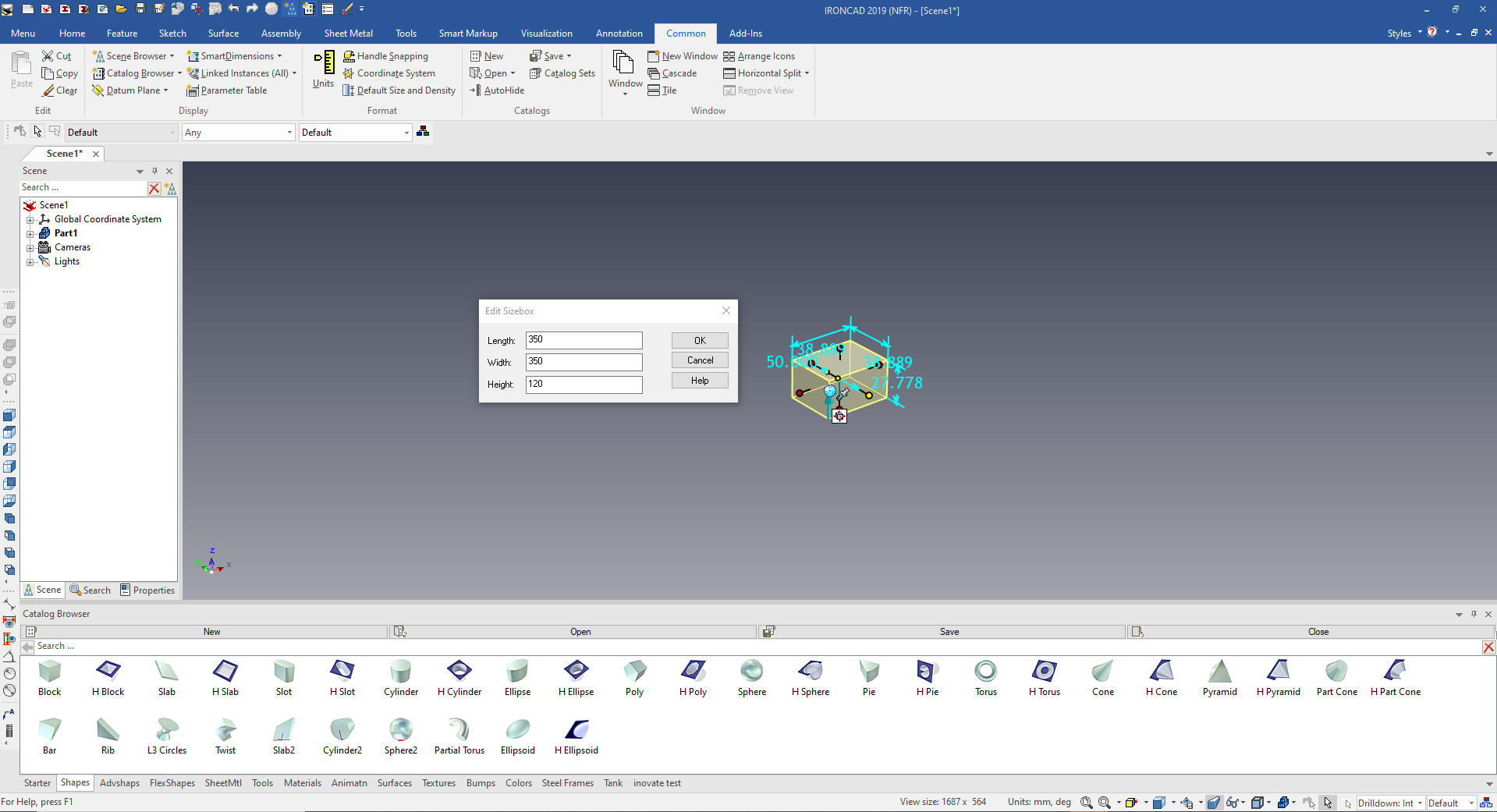
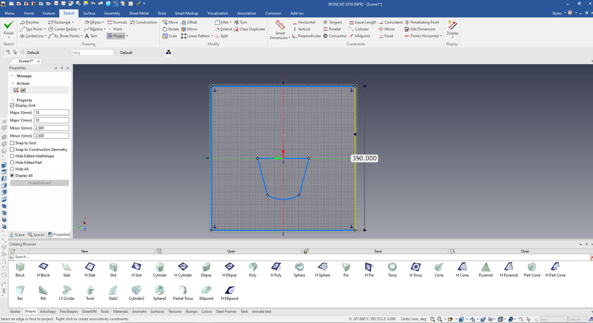
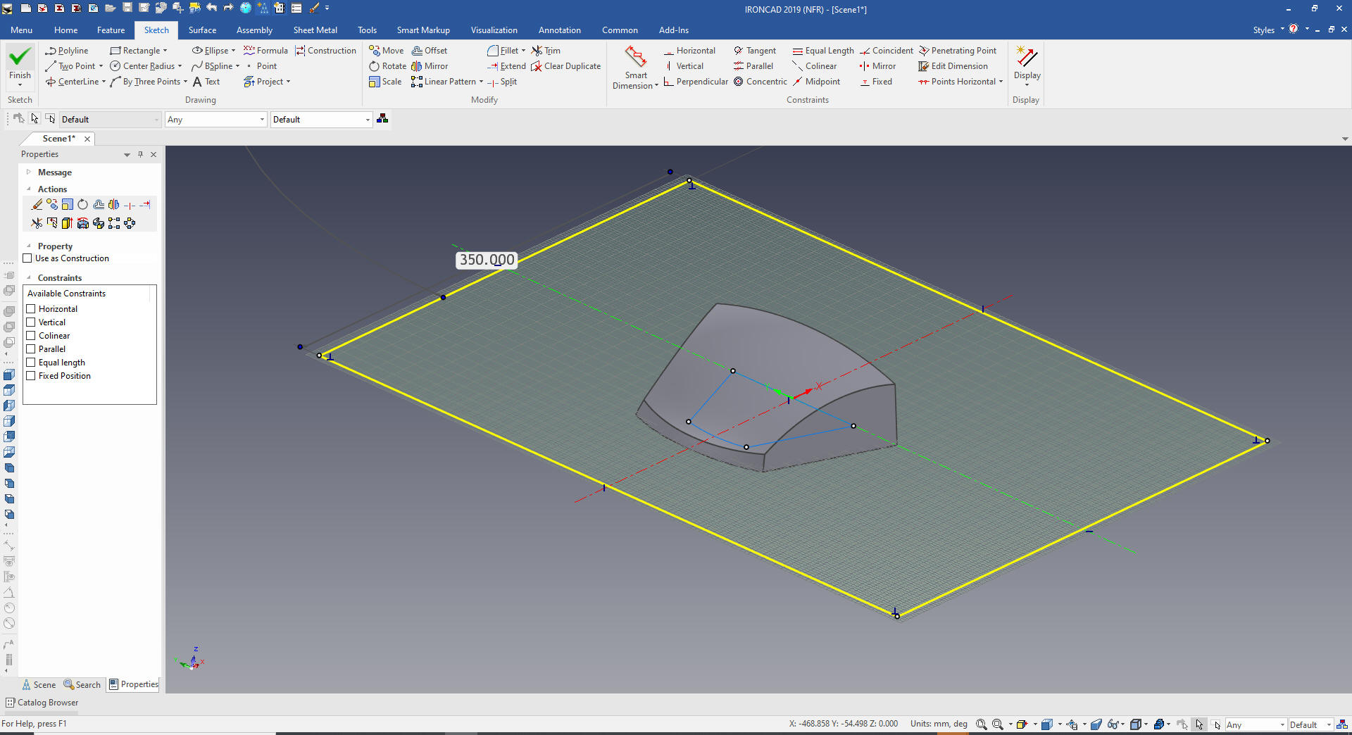
First thing were are going to do is drag and
drop a block from the shapes catalog and size it to 350 X 350 X 120.
It will all make sense in a bit.
Note: Why does IronCAD
call it a scene instead of a workspace? IronCAD was first released
as a graphic design program called Trispectives. It still has much
of the graphic design functionality. It truly is a wonderful mixture
of professional 3D CAD and graphic design, which puts it in a much
more flexible category as compared to the very mechanical
engineering focused Solidworks clones.
IronCAD's sketching planes are an integrated
part of the feature. So we do not have starting planes. It does have
a basic coordinate system with planes but they get more in the way
then help.
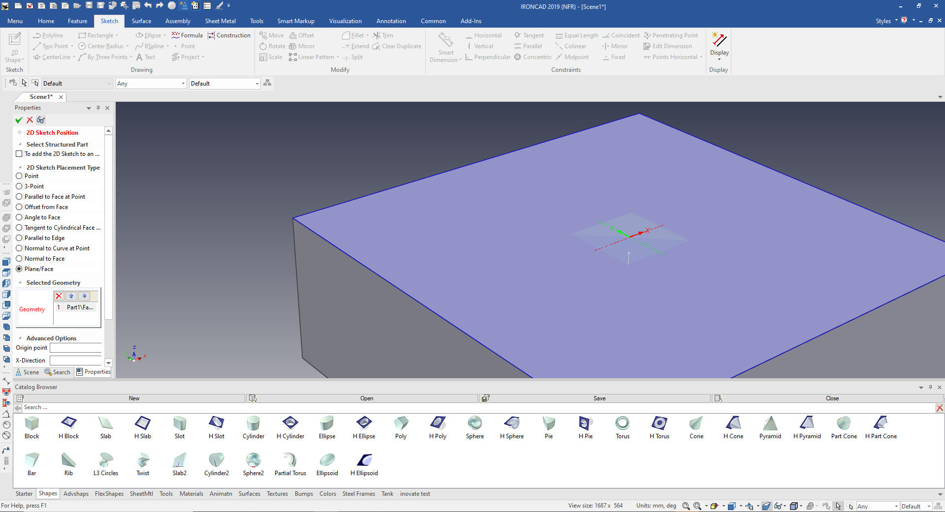
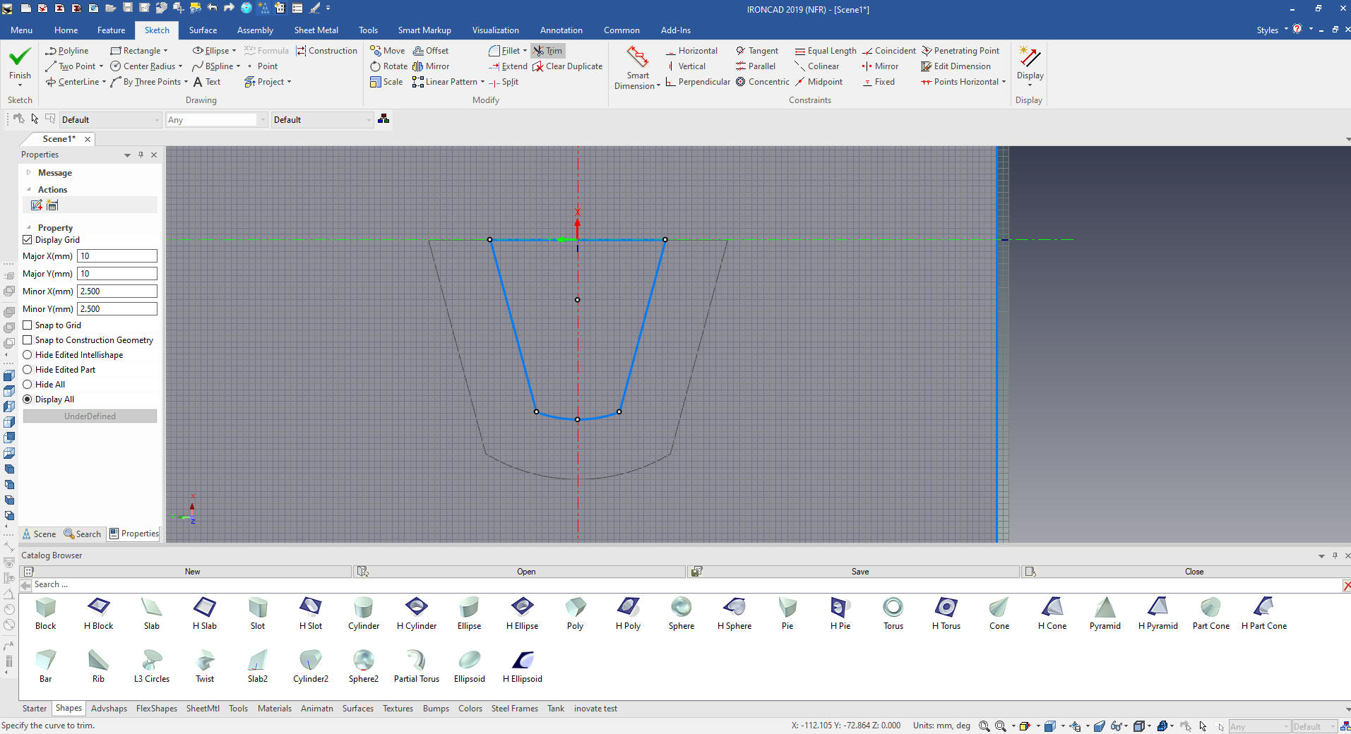
This part is made up of two sketches will
create the first standalone sketch at the middle of the block.
I will just create the sketch, it is very
similar to all 3D CAD package.
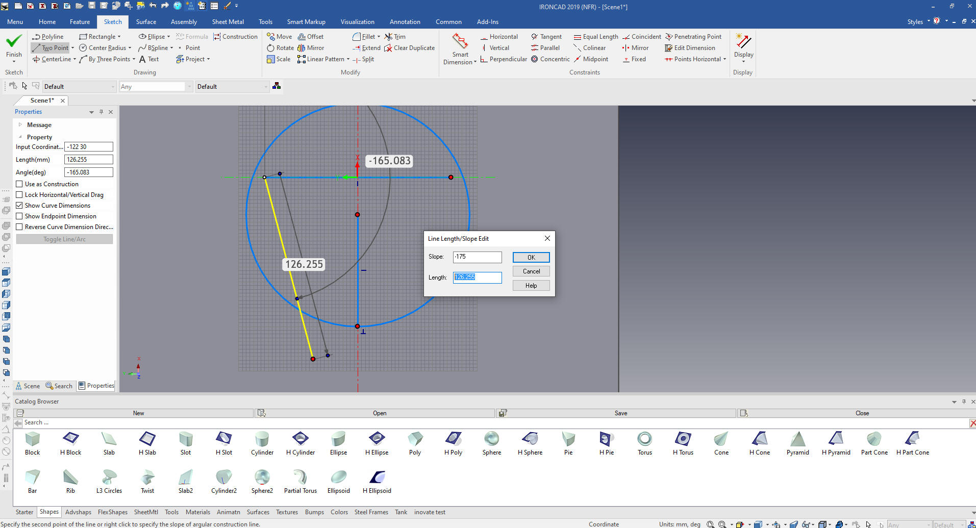
The left button is explicit and the
right button give you the option to set the size of most entities. I
am creating a line and it is asking me the size and angle.
I am showing this function. We will mirror
the line.
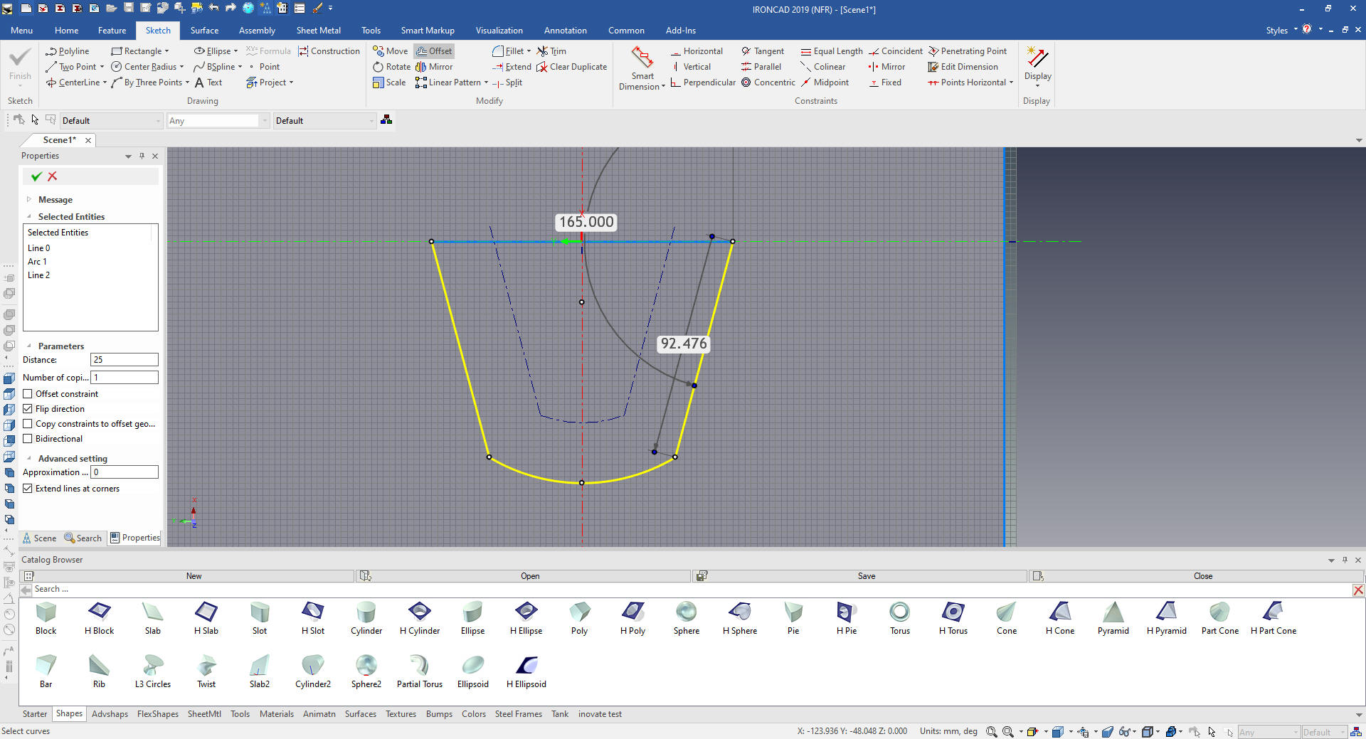
We
project the edge since we will be set to remove. We clean up the
sketch, notice we do not create any constraints.
Now I
copy and paste the sketch to create the second sketch and name them
both top and bottom.
I will edit the top sketch.
We clean it up.
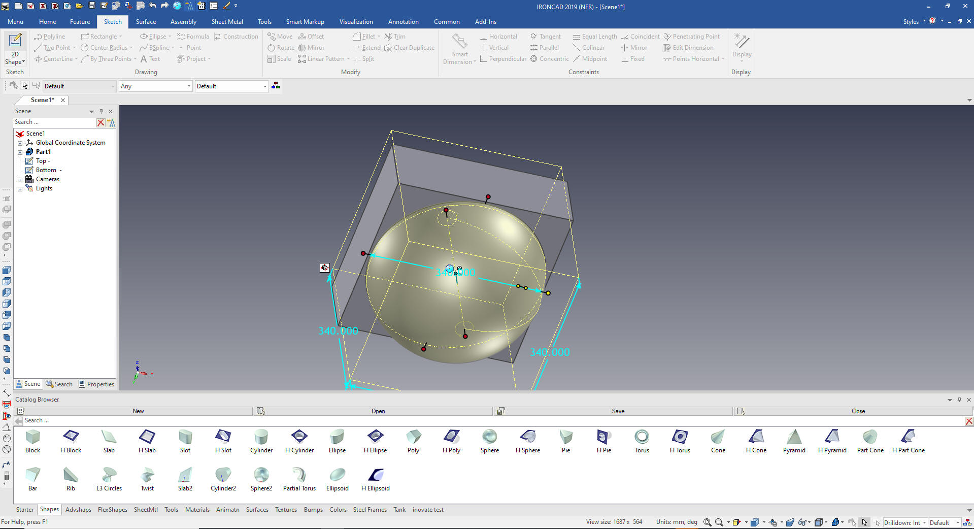
We will now drag and drop a sphere from the catalog and set it
to 340 at the middle of the bottom of the block.
Now we will drag and drop another sphere set
it to 320 and locate it at center of the first sphere.
Of course we can see it. Now my method of my
madness should be coming apparent.
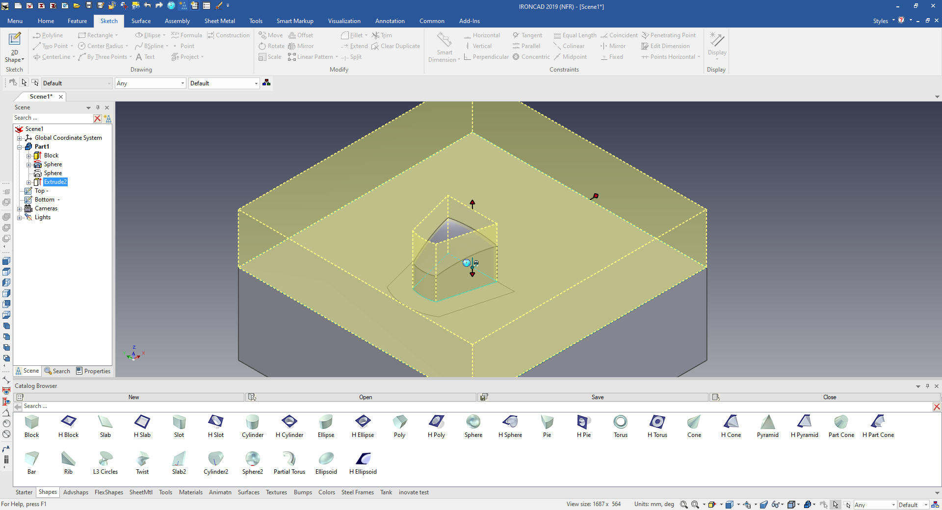
We will suppress the 320 sphere and select
the top sketch extrude options and set it to remove to create the
top of the part.
We will now unsuppress the 320 sphere and
select the bottom sketch extrude option and set it remove. We make
sure the top extrusion is before the bottom.
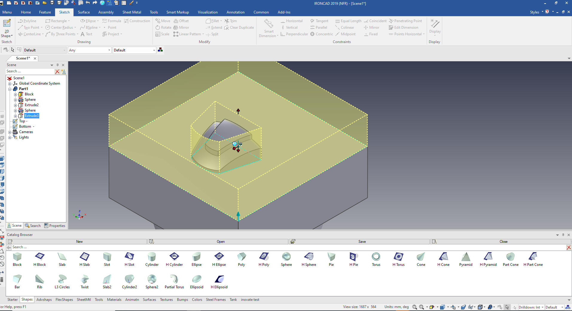
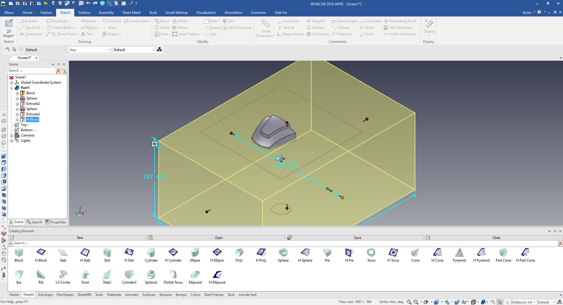
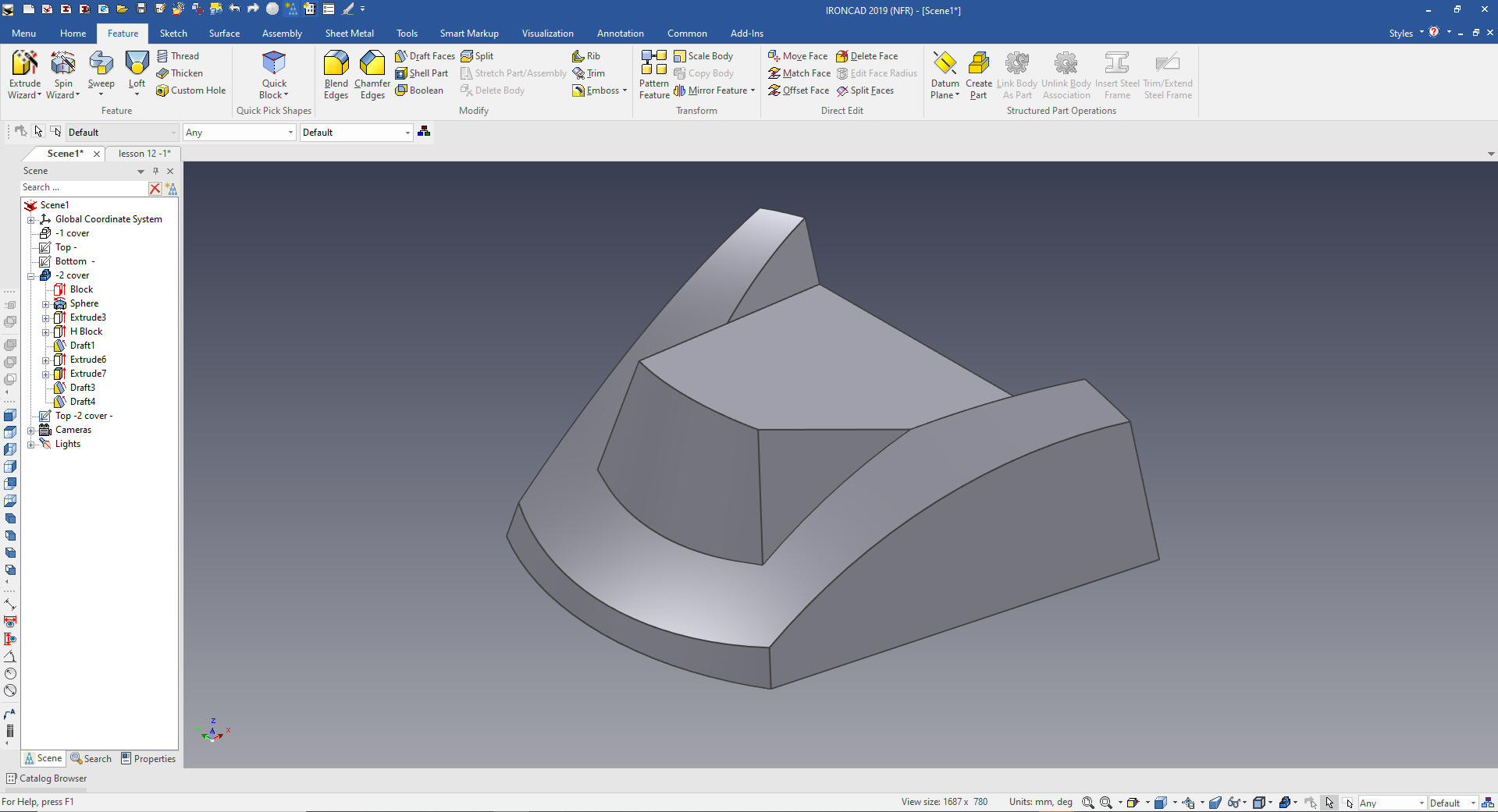
We no drag and drop and hole block and size
it to include the spheres and block. I call this feature based
modeling. We will also suppress the top and bottom sketches for
future use. You can set it to not consume the sketches.
We now have our cover ready for the next step
of drafting the faces.
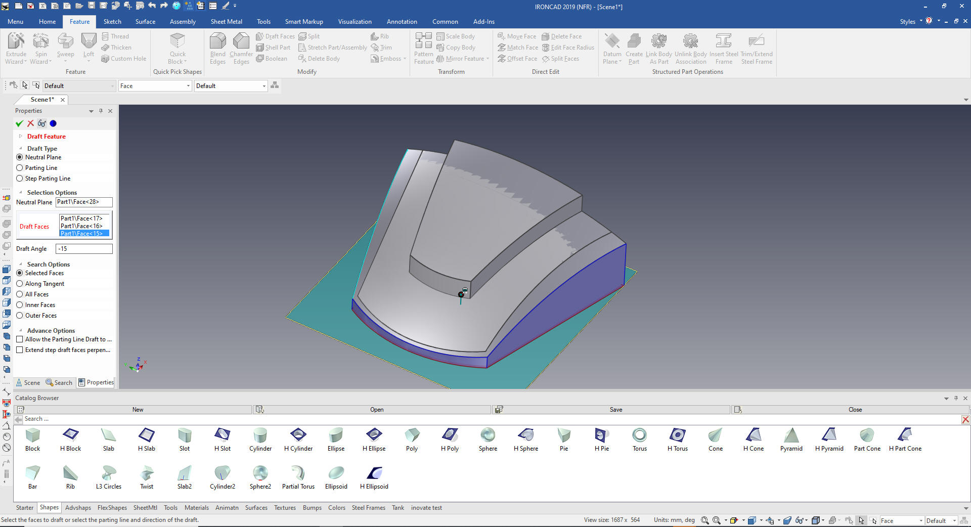
First will use the Draft Face function on the
bottom faces.
Now for the top faces. We use the Draft
Face function again but this time use the parting line option.
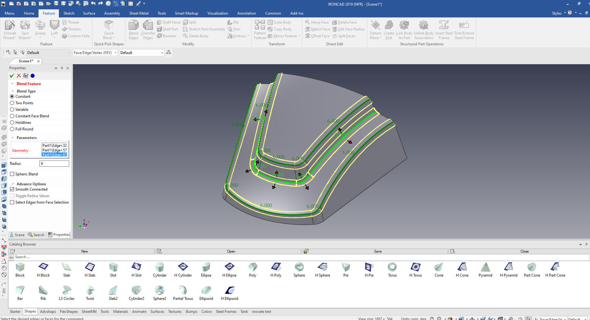
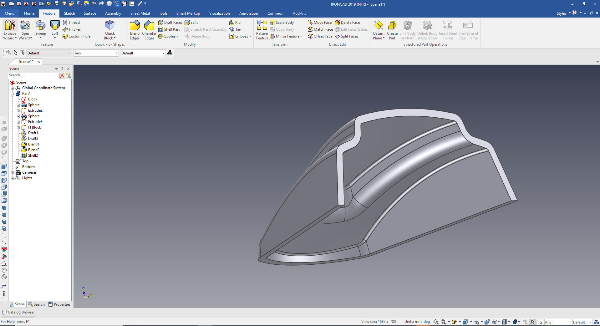
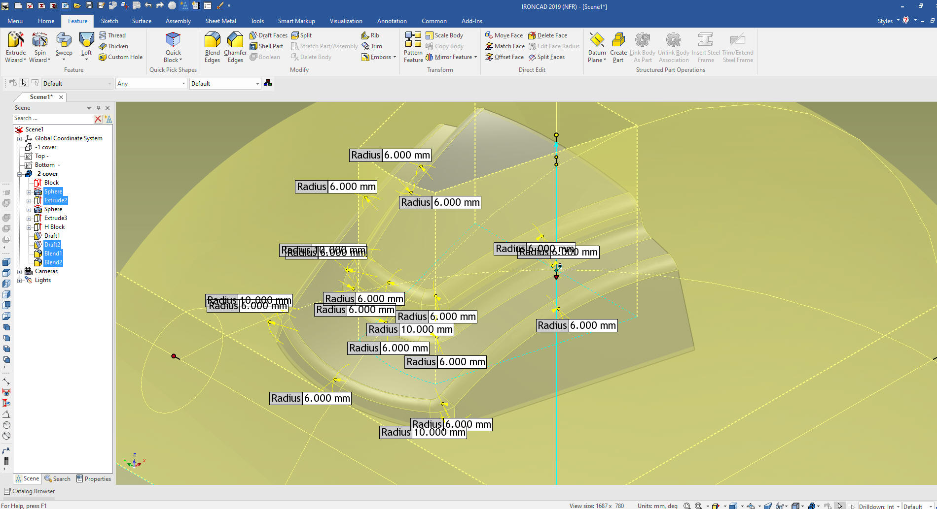
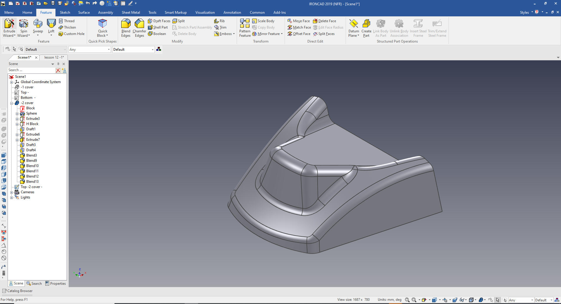
We will now add the blends.
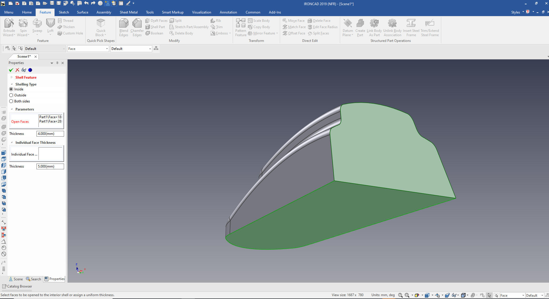
We
just shell it.
We
are done with the part.
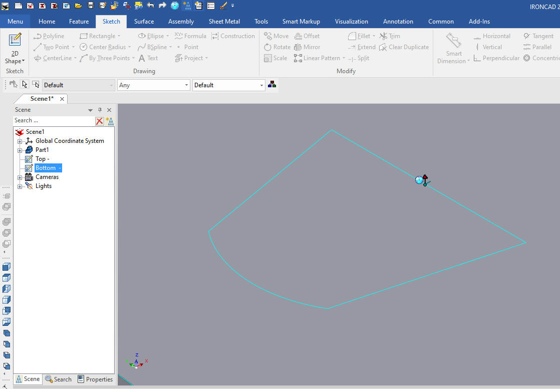
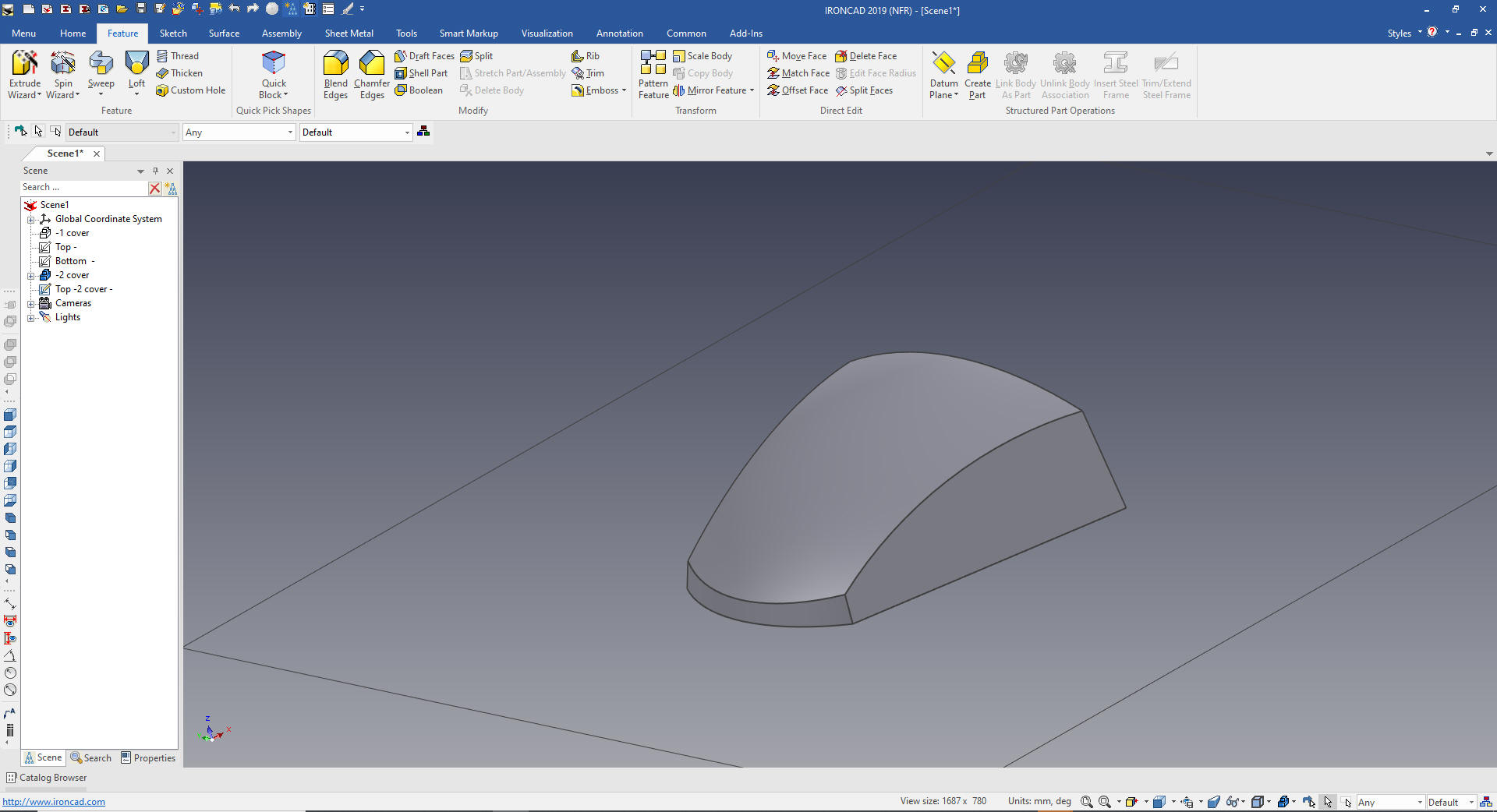
A different view. You many have
noticed the catalog is gone. You mostly use it in the Autohide mode
for more design area.
Now to create a similar part -2 Cover
First thing we do is copy
and paste the part. I renamed
the first part -1 Cover and the new part -2 and suppress, we can do this
because IronCAD is a single model environment.
We delete the
the blends and all the three features that make up the top shape.
Now we have the base shape. We will copy the top sketch and rename
it to top -2 cover.
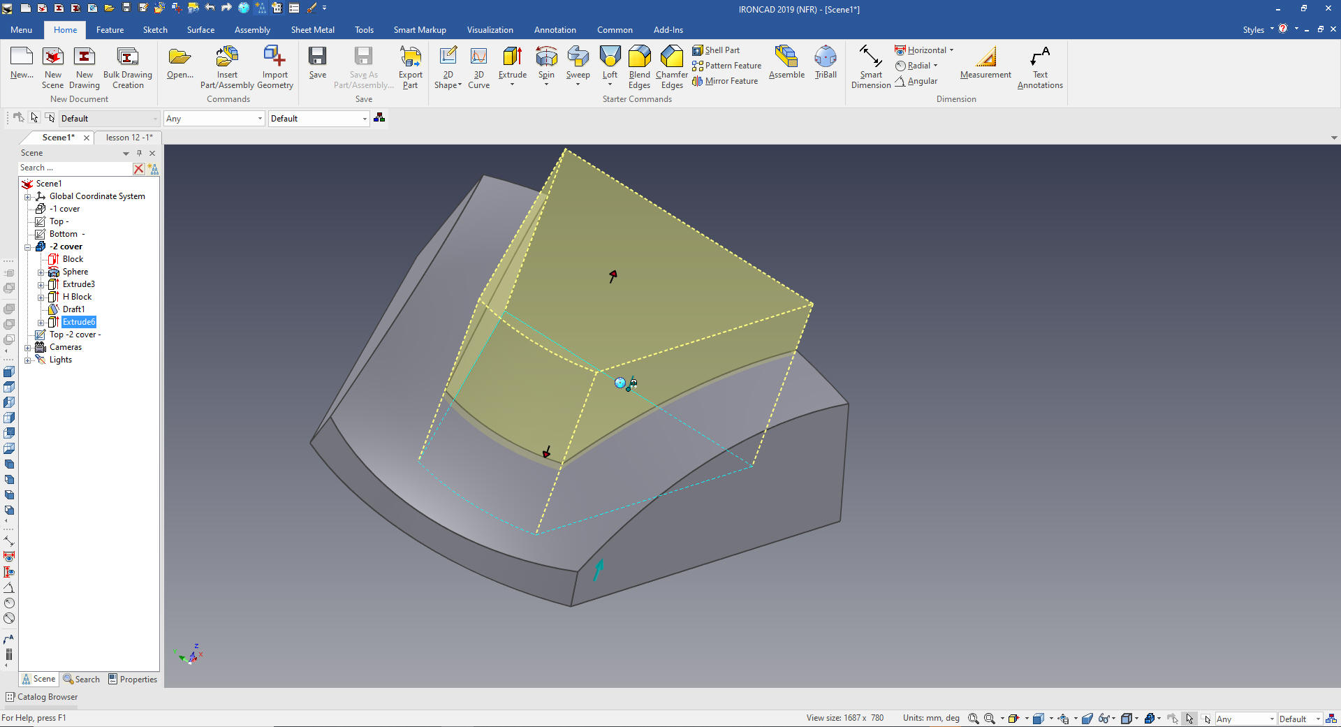
We
will edit the top -2 cover by deleting the outer edges since we are
going to extrude add
we
extrude the sketch to break through the shape and set to remove
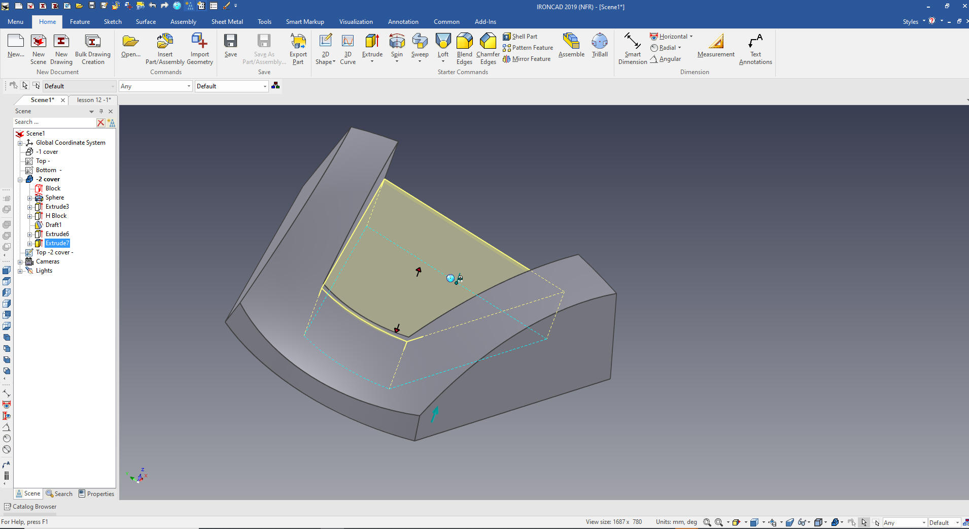
Using the same sketch we are going to extrude add to 20mm
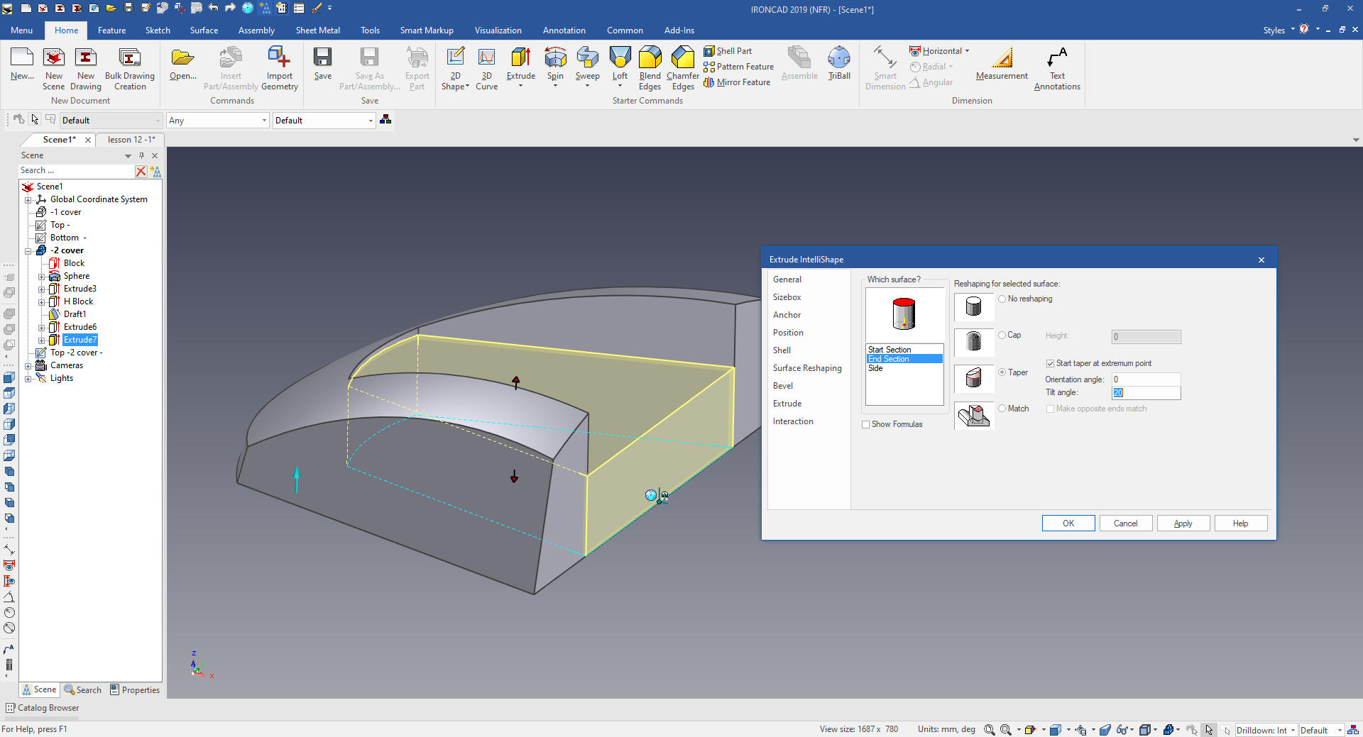
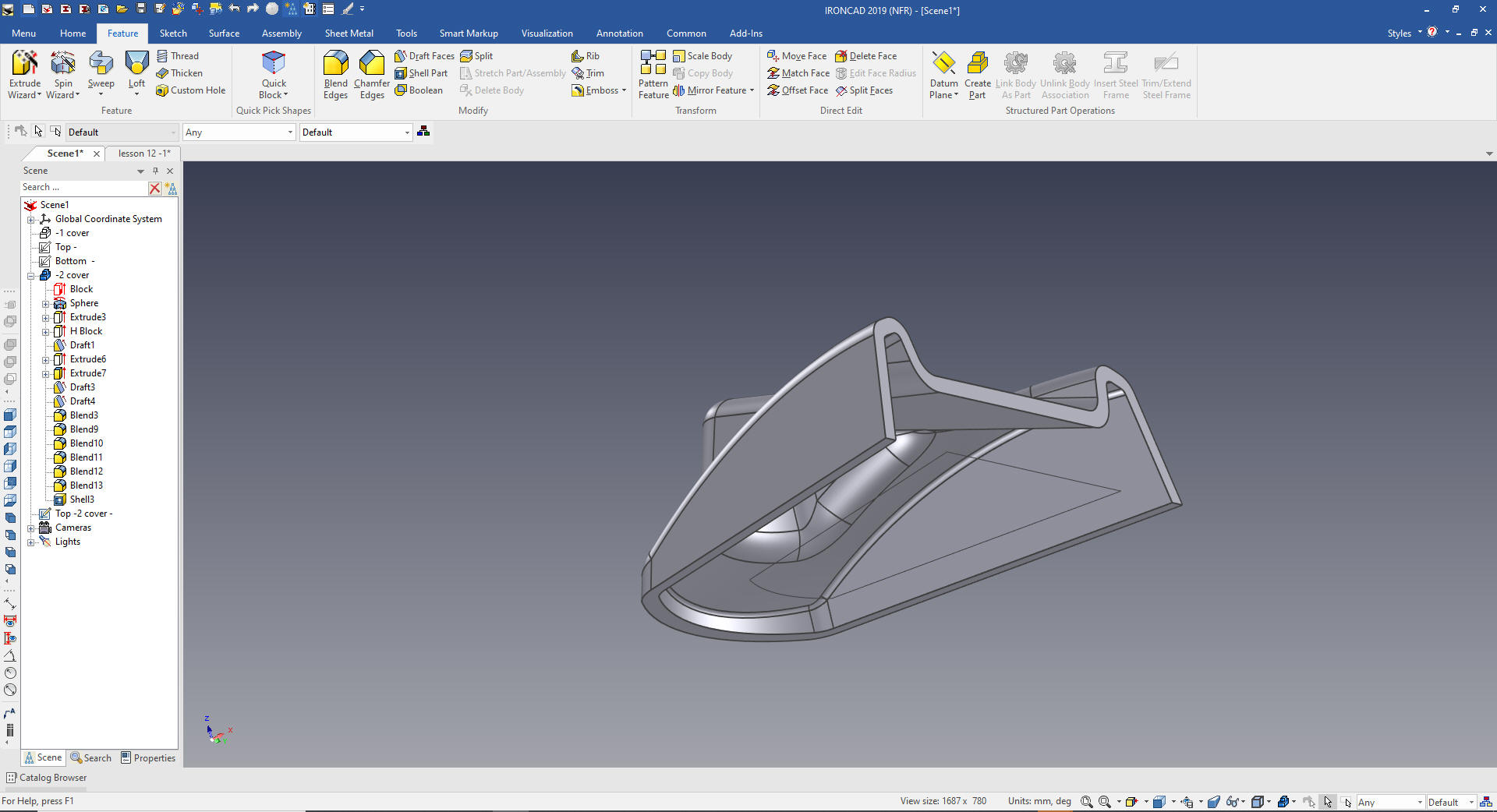
The next step is completely unbelievable
to a Solidworks clone user. We are going to select the feature in
the scene browser (history) or display with the right mouse button
and select Surface Reshaping.
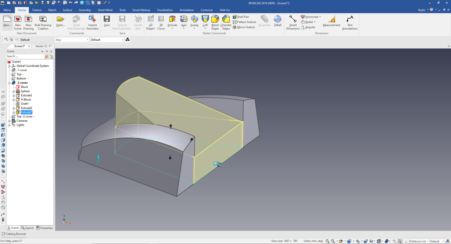
Each feature can be edited individually.
We select the end section, taper with the start taper at extreme
point and set the angle at 20.
This is only a function that is unique to
IronCAD.
You can learn more about this powerful
functionality here.
When you create a 3D model from a drawing you
have to do a detailed AID to assure you
have duplicated the drawing. You should also have someone check it
if it is in a production environment.
When
we create sheet 2 and set it to configuration -2 COVER
This is
another stark examples
of how Streamlined Sketching and Feature Based Modeling utilizing IronCAD's drag and drop of smart editable
intellishapes from a catalog and
the use of the Triball can increase productivity easily 5X. I
usually estimate 5X increased productivity in conceptual design and
10X in changes, and I believe I am being conservative. IronCAD can
edit most of the Solidworks clone parts and assemblies faster than it
can be done in the native CAD system.
Give me a call if you have any
questions. I can set up a skype or go to meeting to show this part
or answer any of your questions on the operation of IronCAD. It
truly is the very best conceptual 3D CAD system.
If you are interested in adding professional
hybrid modeling capabilities or looking for a new solution to
increase your productivity, take some time to download a fully
functional 30 day evaluation and play with these packages. Feel free
to give me a call if you have any questions or would like an on-line
presentation.