|
Learning IronCAD! Lesson 4 The IronCAD Intellishape Deconstructed What the Heck are we Dragging and Dropping? 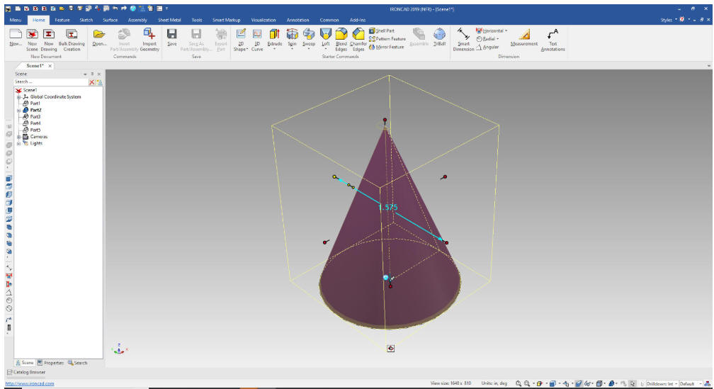 |
|
If you would like to join
in:
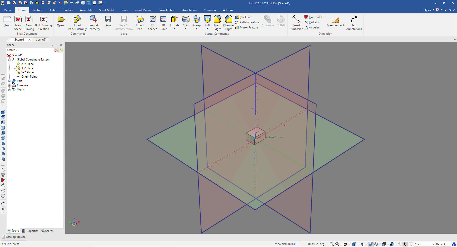
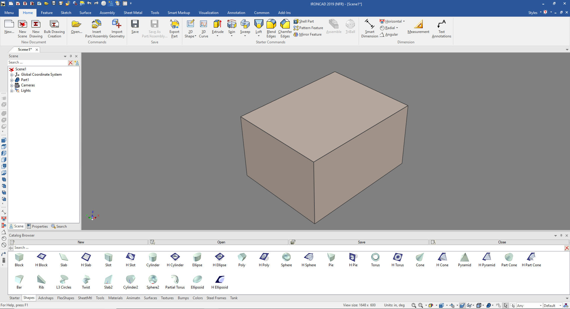
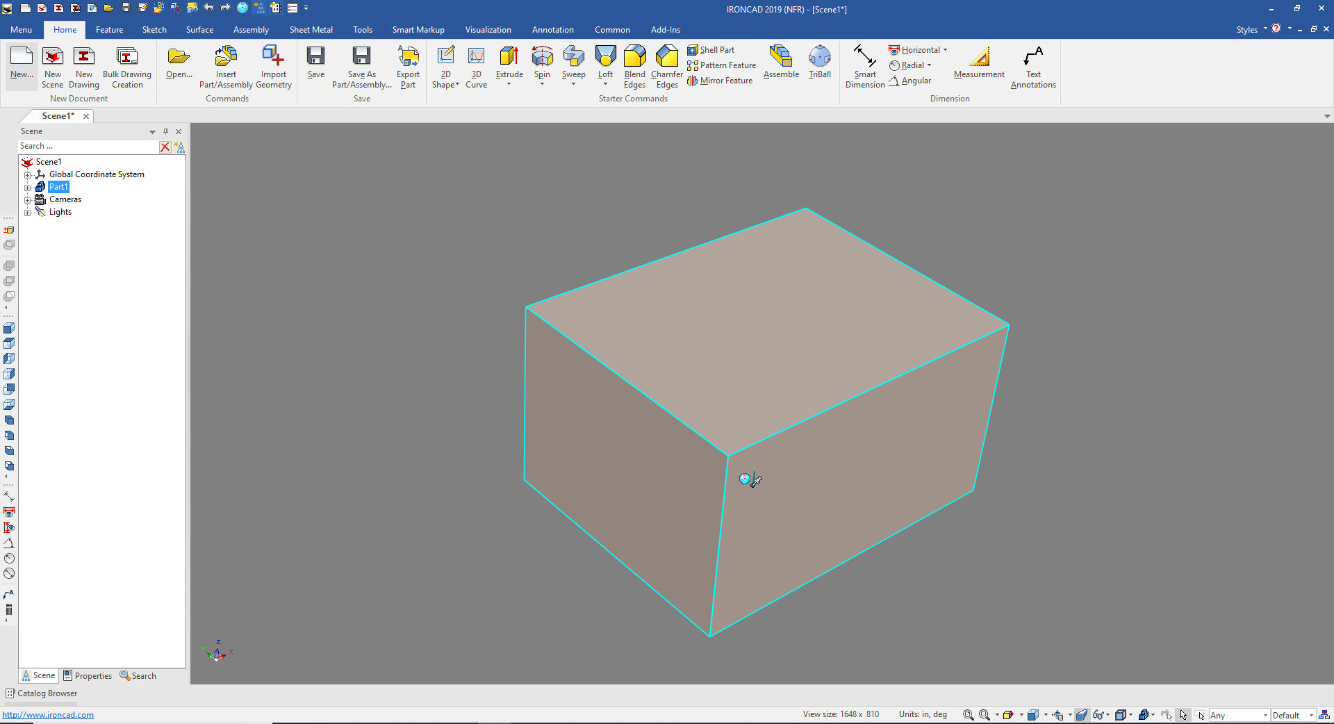
Download IronCAD here This is a 30 day fully functional IronCAD evaluation including the Translators for all of the popular programs. Go ahead and import parts and/or assemblies. You can actually modify the parts faster than in the original system. I will be posting new lesson relatively often. If you are interested send me your email and I will make sure you get the new lessons. Please start with the lesson 1. Learning IronCAD! Lesson 1 Setting up the Scene (Workspace) If you get ahead, here is a great getting started Tutorial. Self-Paced Training Guide - Introduction IronCAD Intellishapes IronCAD is only program that has drag and drop shapes from standard or custom catalogs. But what are these shapes? These are not just some simple primitive shapes. Introducing the Intellishape. IronCAD shapes are far beyond the primitives offered in other systems. We call them Intellishapes, not because they are driven by sketches but that they can directly be modified in many ways. First we drag and drop a block into the scene from the shapes catalog. Note: Why does IronCAD call it a scene instead of a workspace? IronCAD was first released as a graphic design program called Trispectives. It still has much of the graphic design functionality. It truly is a wonderful mixture of professional 3D MECH CAD and graphic design, which puts it in a much more flexible category as compared to the very mechanical engineering focused Solidworks clones. When we drag and drop a shape it automatically puts it at X0YOZ. Here I show the Global Coordinate system by tuning on the planes. We rarely work with this but I want show you how it worked. It is one of the options in the show dialog box.
We will turn the planes off and continue.
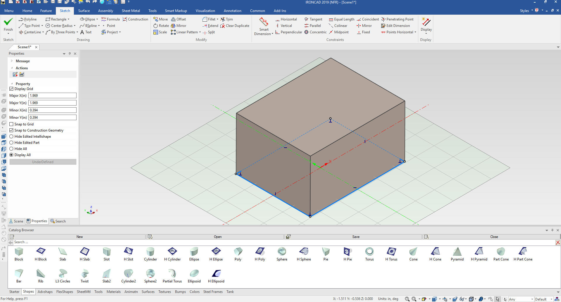
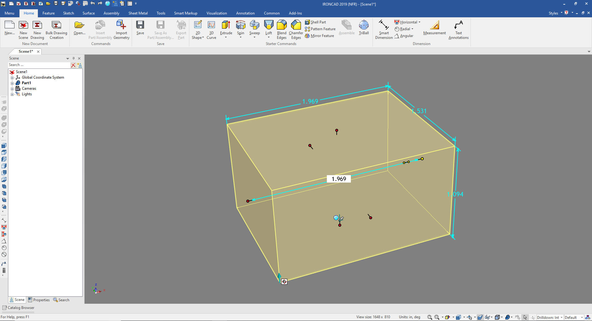
First, all Intellishapes are based on sketches we select the feature level and select Edit Cross-Section.
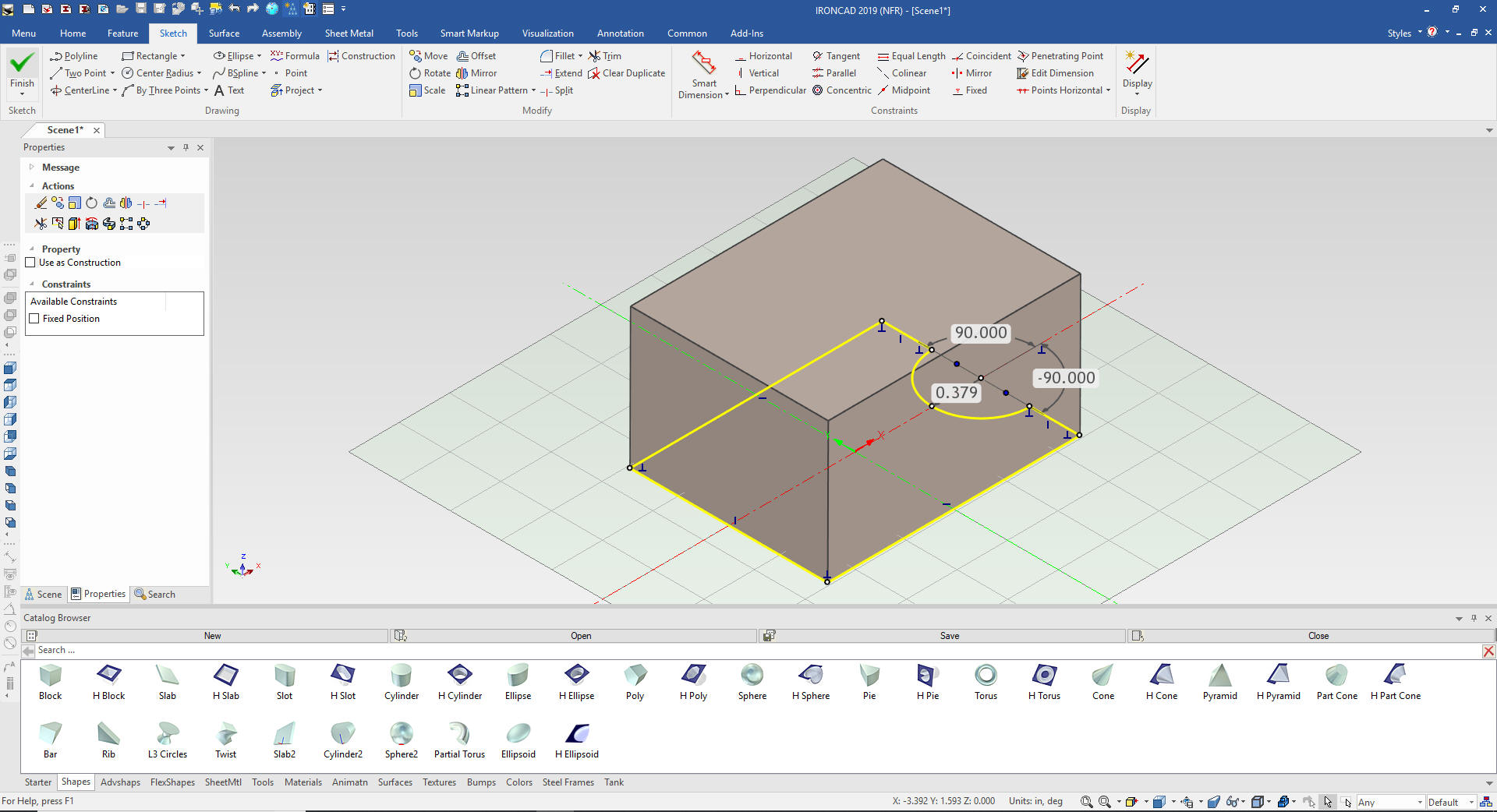
Now I am sure I do not have to explain a sketch to you. It is the basic building block of all 3D CAD systems. We can edit the sketch to change the shape.
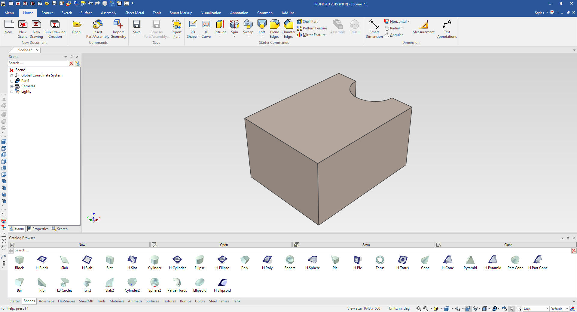
You can do this with most of the Intellishape, there are a few that are incorporated into more complex shapes controlled by the handles. Here is our changed part
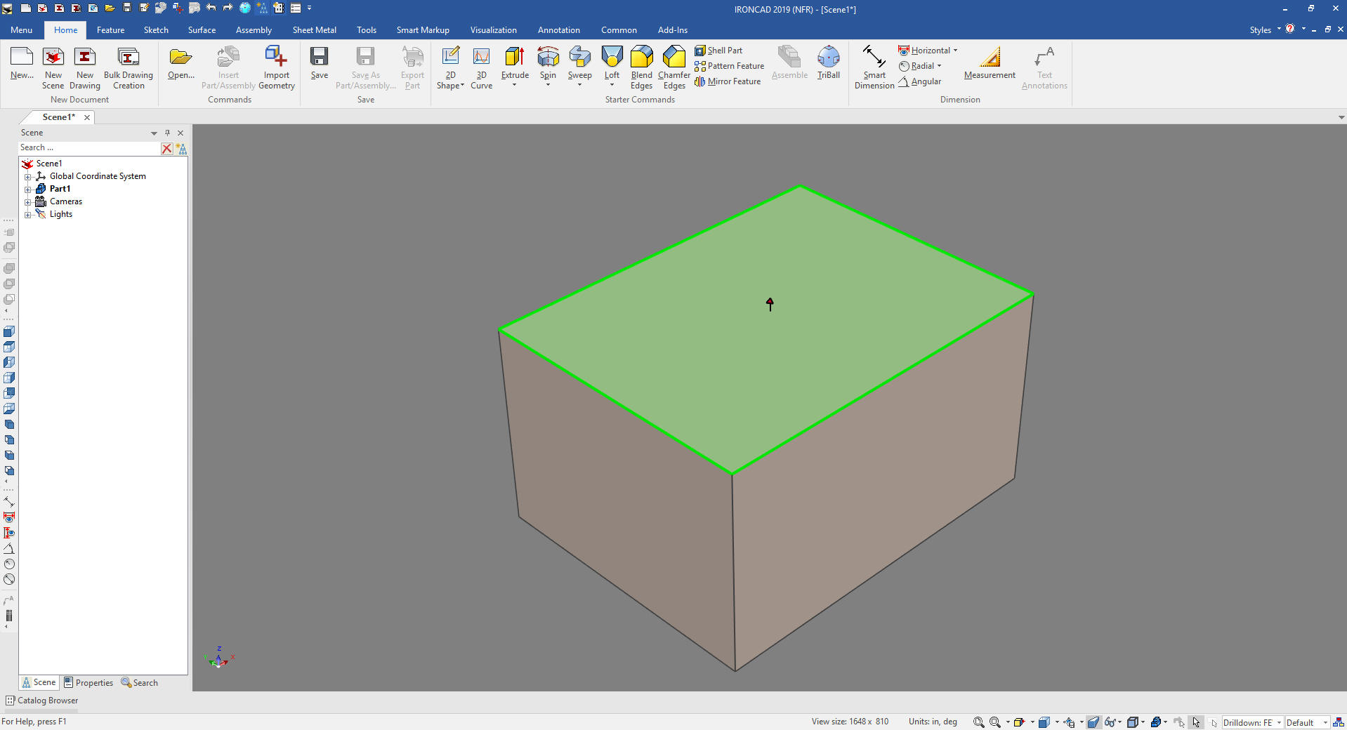
I will hide the catalog as we investigate the Intellishape Properties IronCAD has four levels of selection. First is yellow for assemblies, blue is for the part shown here.
The next level is the feature level which is yellow. Note: I turn on the size box dimensions, which a selection when you right click in the scene and select "Show" in the dialog box. There are many selection to set the scene properties.
The third level is face or surface. But we will be only working with the feature level. IronCAD is such a different and flexible way to design.
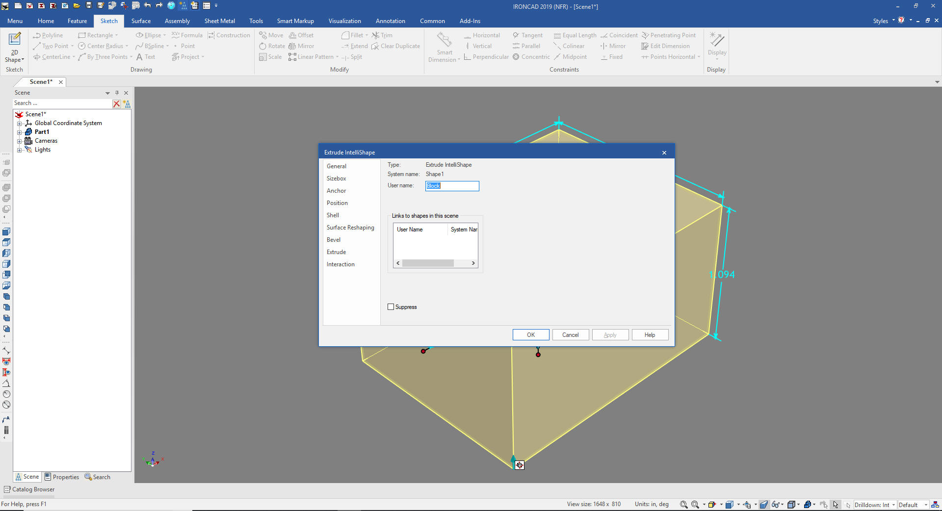
Back to the Intellishape. We left click on the block and get it to the feature level and right click and in the dialog box at the bottom we select "Intellishape Properties". You can get to the "Surface Reshaping Properties" also but we want to see all the options.
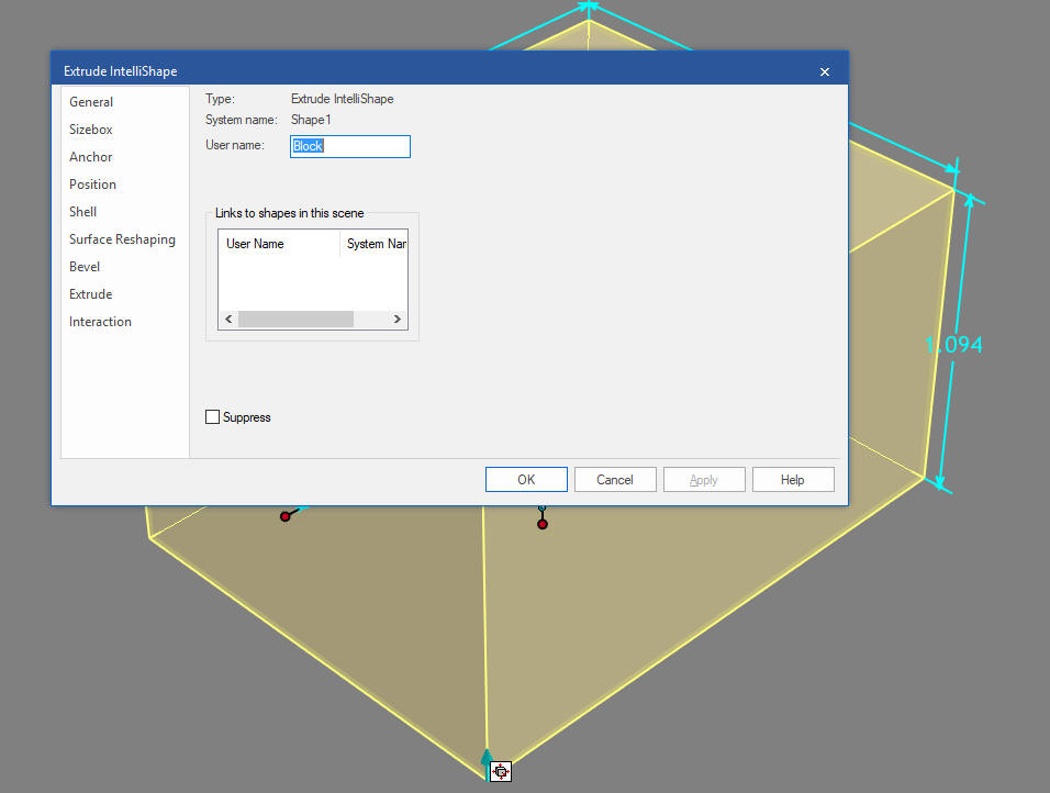
Let's go through some of the options. When you select the "Intellishape Properties" the General comes up. This is just basic information. It shows that it is an Extrude Intellishape.
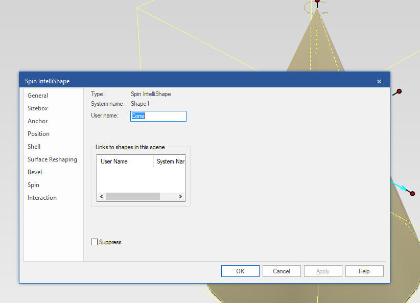
This shows a cone and it is made up of a Spin Intellishape.
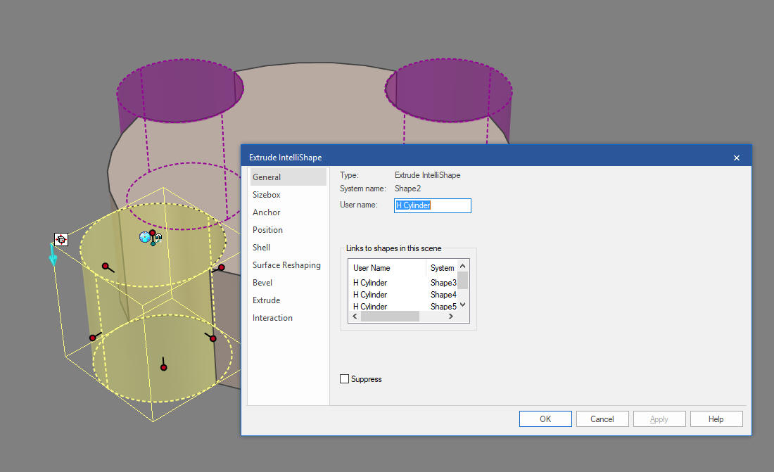
The general option also shows any linked information. Which means the number of times this shape is used in the part. You can edit any one of a linked features and all are affected.
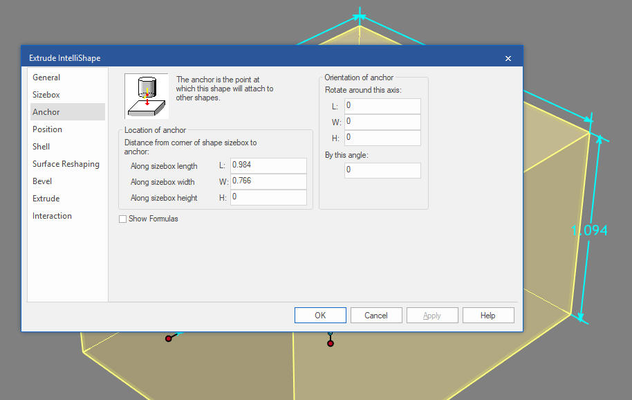
Anchor is the origin of the Intellshape. It orients the Intellishape when you drop it into the scene or other shape. Anchors are not important when you are learning the basics but can be important when you are creating custom shapes and putting them in custom catalogs. You can use these anchors to build specific custom fabrications and other unique assemblies by dragging and dropping shapes and having them snap into place. We even have a free package called Compose that can be setup in such a way that a salesman could create a custom configuration of a product while sitting with the client.
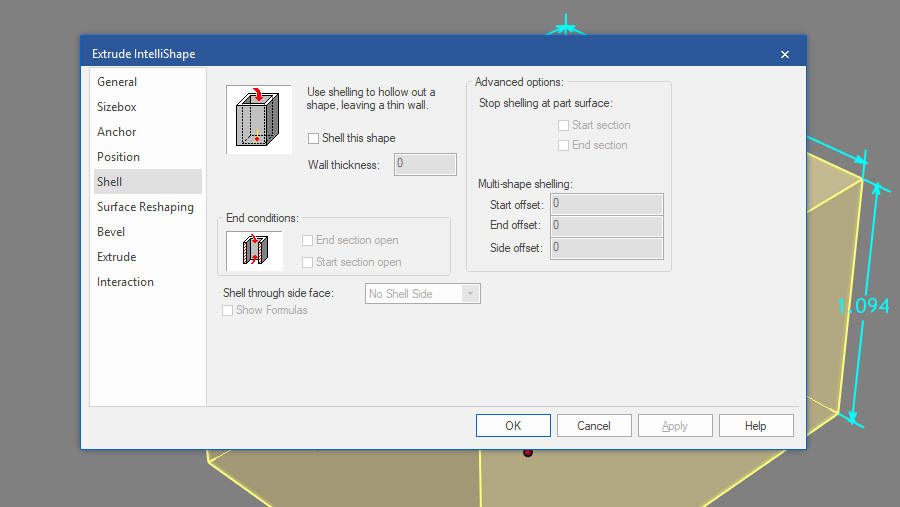
Shell feature is very cool.
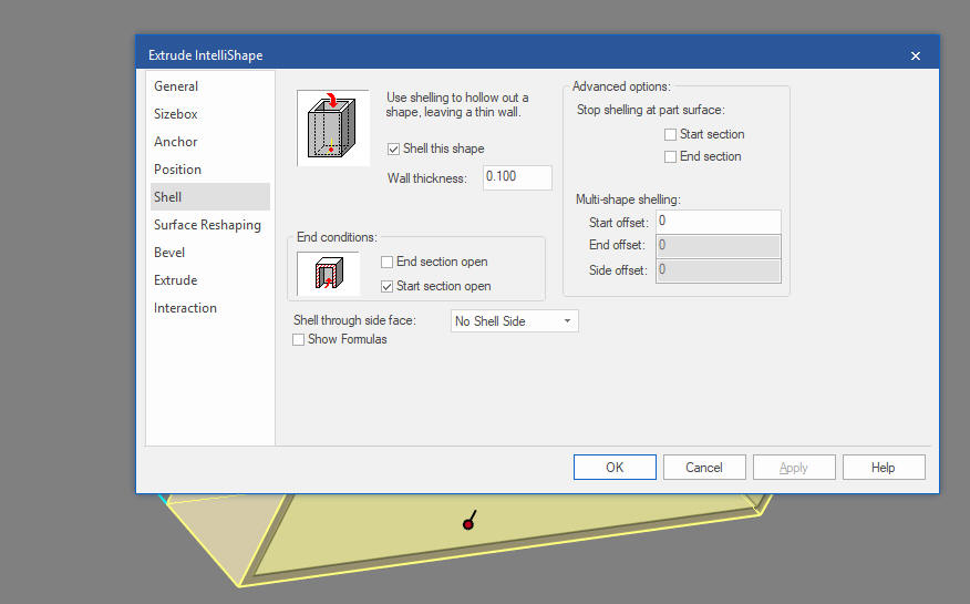
Let's take a look and see how it works. We drag and drop a block from the catalog, select the feature level and shell with these options. I takes a bit of playing but with
We have shell the bottom of the block.
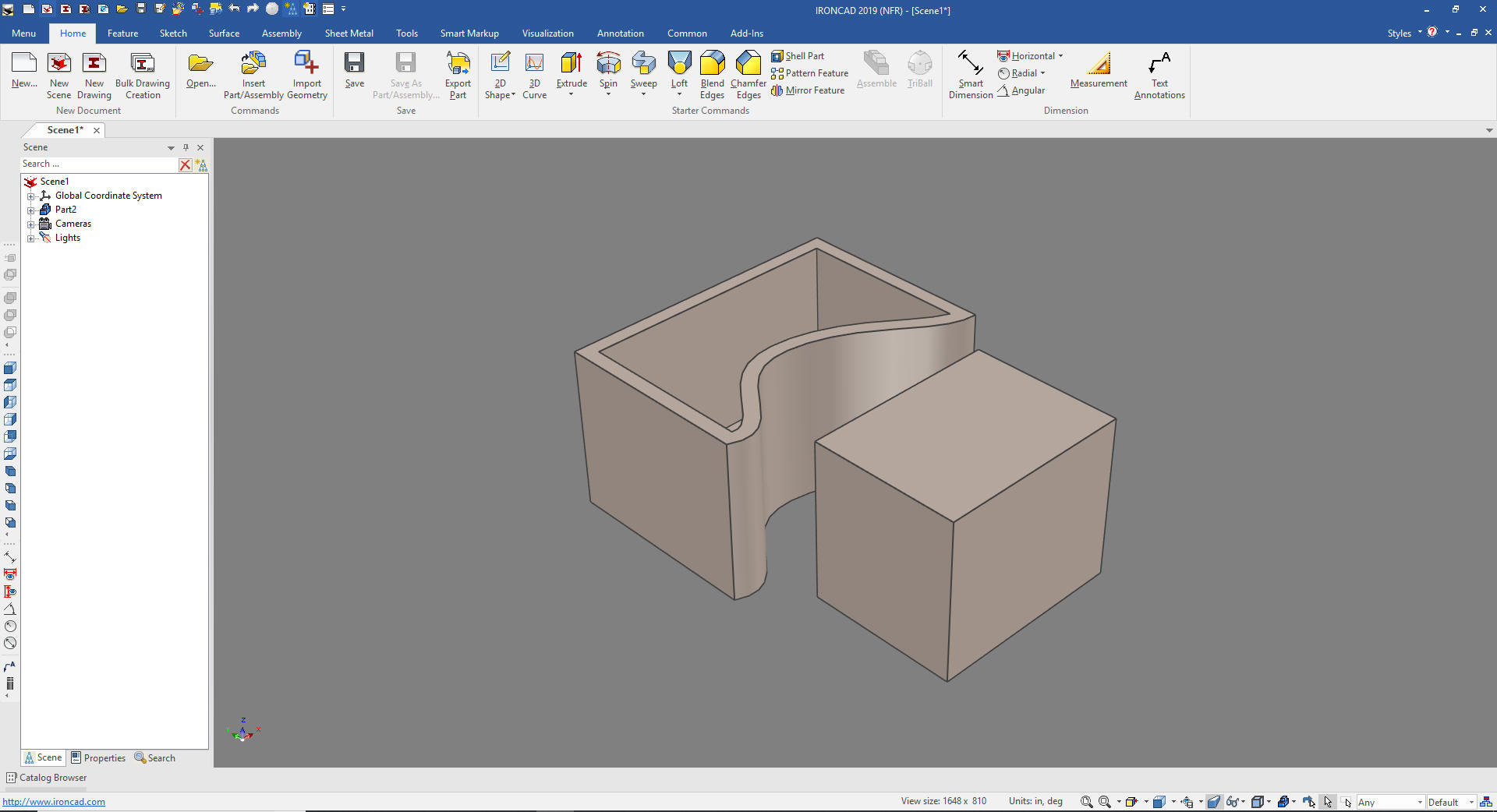
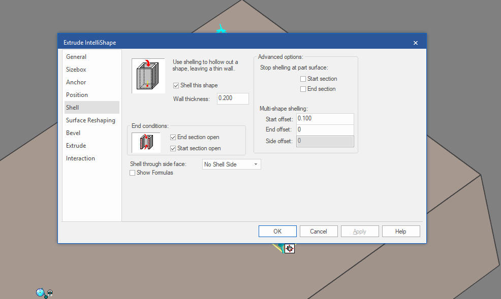
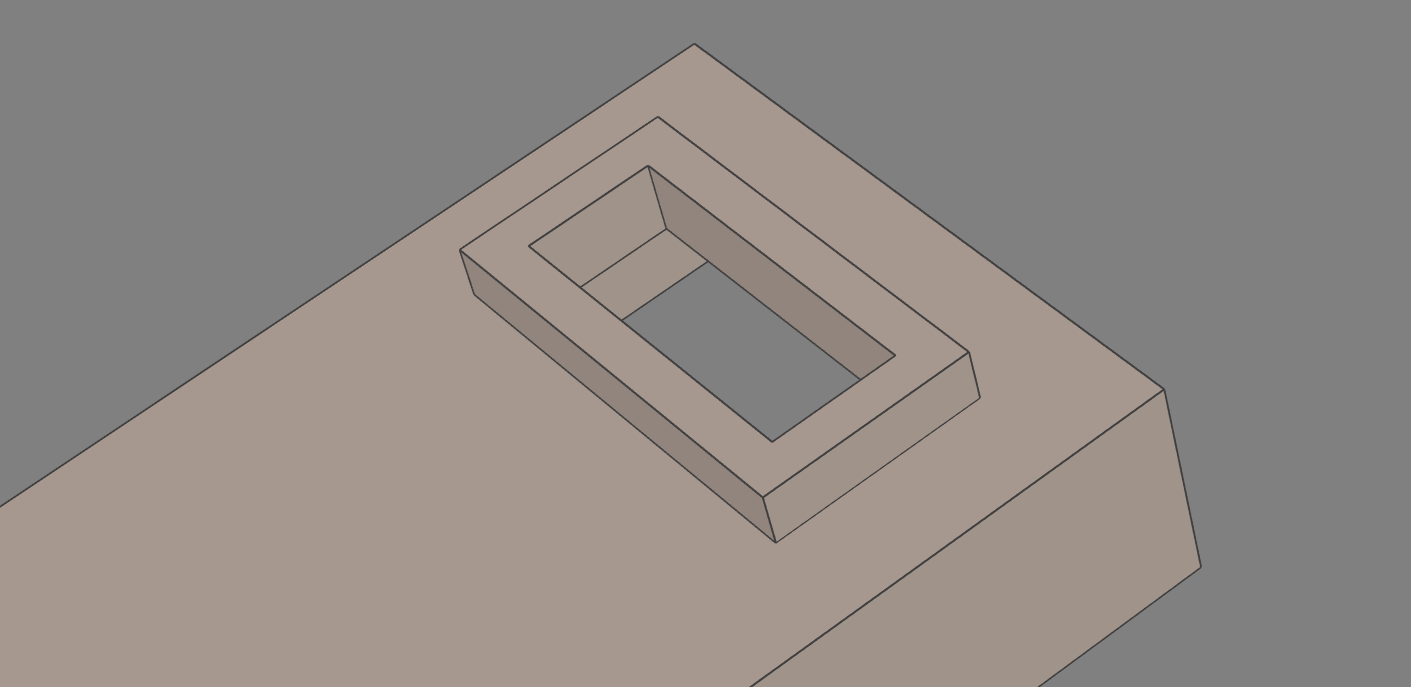
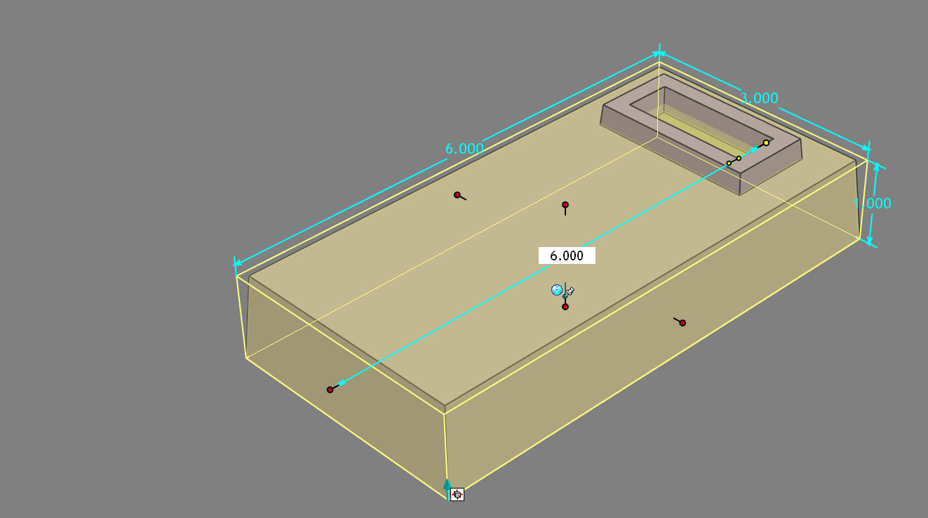
Now we add a block to the top of the block
Notice that our shell extents through the other block
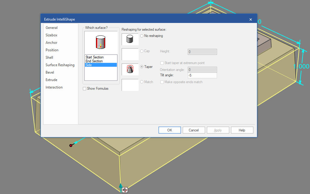
The next option is Surface Reshaping. I will add draft to both the bottom and top blocks. We will at -5 degrees to the sides.
You can see the change of the lower block.
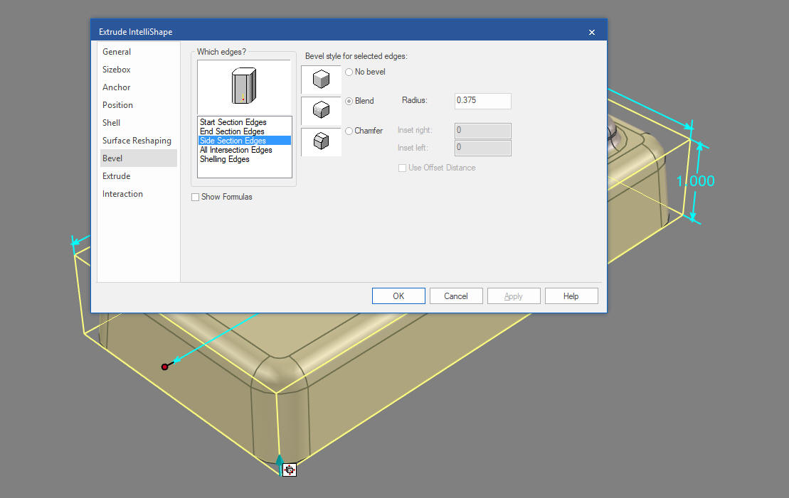
Now for the bevel options. Now I defined a lot of options. I add .375 for the sides of the big block, .25 for the end section edges, .150 for the shell edges, on the smaller block I added .25 for the sides, .125 for the end, .15 for the shell and .125 for the intersection edges.
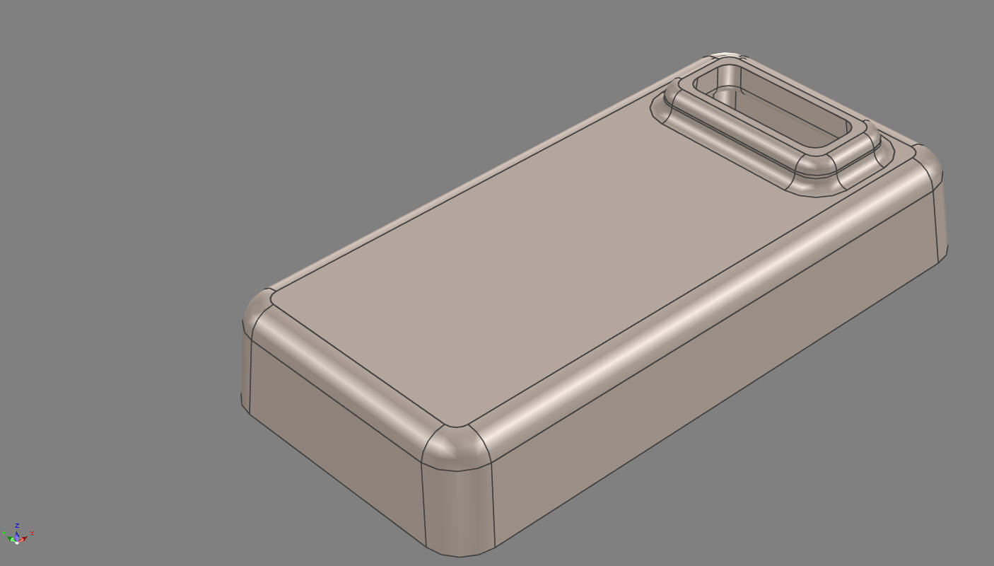
The final results.
Before we move the next option I want to show one of the function on
Surface Reshaping. I create a block and edit the Cross-Section and
add spline. The drag and drop another block on the the back face and
pull it to the front.
 We will set the block to match. 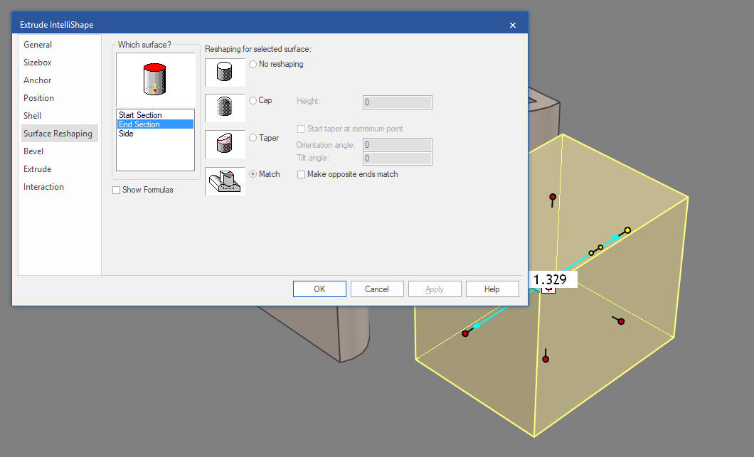 We just pull the end handle and you can see the edge of the block matches the face. 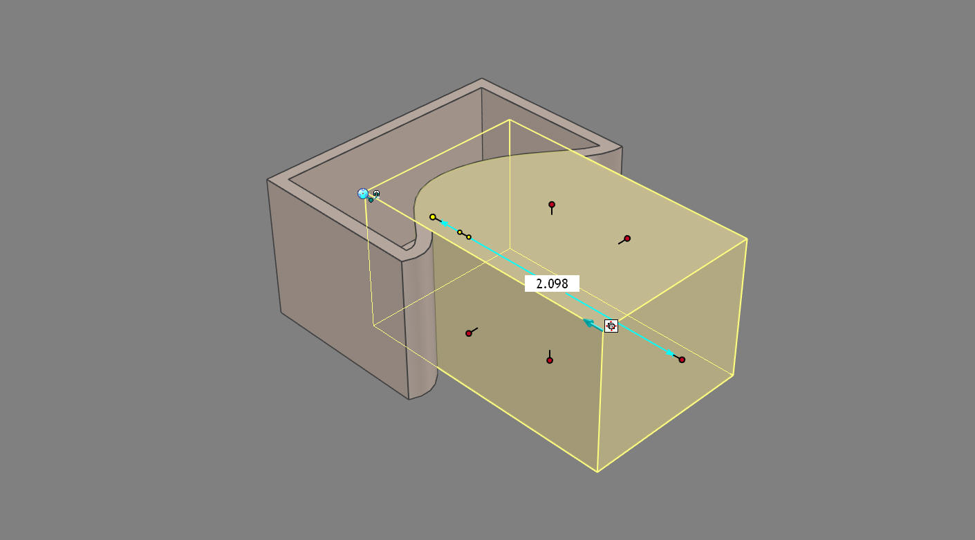 Now the next option is for the unique operation. The title of this dialog box is Extrude Intellishape, where we can actually edit the length of the extruded feature. You can see it is 1.094. You can also set the handles. 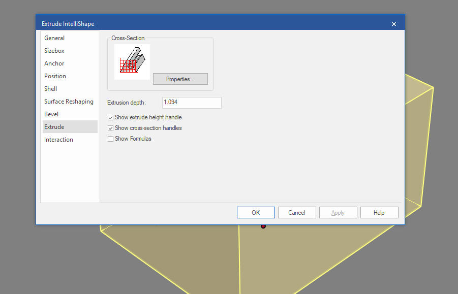 The title of the dialog box is Spin Intellishape and we can set the rotation angle. 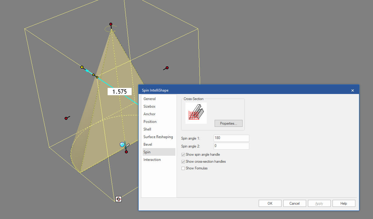 Lastly we have the Interaction Option. This defines the shapes functionality as it is relates to the scene. We mostly just accept the defaults. 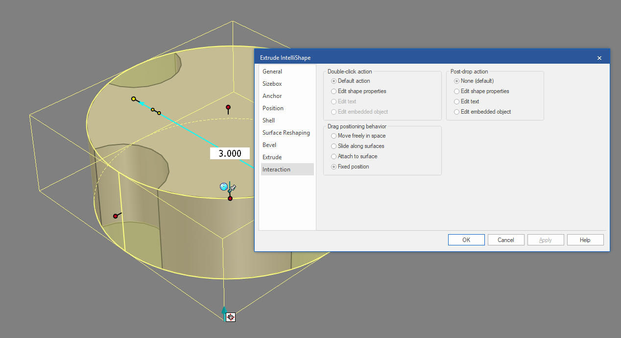 Would we design completely this way. No, while it can control much of the features it does not provide the ability to work with all aspects, so you may add draft farther down the design process and using the shell feature separately. Once you understand its limitations it is quite productive. Lesson 5: Integrated History Based/Direct Edit Modeling Again please download IronCAD and start experiencing the increased productivity. Today, engineering is a bottle neck due to the time consuming design paradigm of the major 3D CAD systems. IronCAD can increase productivity on conceptual design 5X and with modifications 10X. This translates to real cost savings. Is 3D CAD Productivity an Oxymoron? For more information or to download IronCAD Here are some exercises that you can do. They will introduce you to more Streamlined Sketching and Feature Based Modeling. IronCAD vs Fusion 360 IronCAD vs Solidworks IRONCAD vs Creo Again, if you have questions please skype me. I am usually available from 4 am to 2 pm weekdays. Weekends usually from 4 am to 10 am. Maybe later, if I have some work, you can always give it a try. Again please send me an email so I know who you are: joe@tecnetinc.com |
|
Please feel free to stop by our website below for a variety of articles on the State of our Industry, interesting articles on 3D CAD Productivity and a few of our projects!
Viewpoints on Today's 3D CAD and
Engineering Industry
TECH-NET Engineering Services! We sell and support IronCAD and ZW3D Products and
If you are interested in adding professional hybrid modeling capabilities or looking for a new solution to increase your productivity, take some time to download a fully functional 30 day evaluation and play with these packages. Feel free to give me a call if you have any questions or would like an on-line presentation. For more information or to download IronCAD or ZW3D Joe Brouwer |


TECH-NET ASSOCIATES | RENDERING OF THE MONTH | CAD•CAM SERVICES
HARDWARE | TECH TIPS | EMPLOYMENT | CONTACT