3D Modeling Techniques IRONCAD vs Solidworks
Lesson Thirteen Drag and Drop Design Streamlined Sketching/Feature Based Modeling
Modeling note:
It is funny,
you may not realize how you model because you have many ingrained
processes from the past. I have been doing Boolean (direct edit)
design since the beginning of solid modeling in CAD. In 1998 I was
part of the IronCAD release and was introduced to history based
modeling, but IronCAD has integrated direct edit so I still had that
functionality available. As I have been doing these comparisons I
realized that I design in shapes. I look at the drawing and pick out
the basic shapes of the part. You can see that in this part.
When I introduce IronCAD's very
flexible design paradigm I have a hard time to get the Pro/e clone
users, like Solidworks and other programs, to understand the drag and
drop design paradigm.
Download IronCAD/Inovate and
take the one day and 17 lesson course. I get rave reviews from my
new customers. Give it a try, this is a fully functional 30 day
evaluation with all of the native translators so you have access to
your legacy engineering information.
I saw some Fusion 360 exercises online and I decided to compare
IronCAD. It quickly turned into a study in modeling techniques. I have created
many comparisons to Fusion 360, Onshape, Solid Edge, NX, Creo,
Catia and Inventor
lessons to show the difference between
IronCAD and my modeling techniques. I found the presenters working
identically wasting massive amounts of time
with overly complex constrained sketching procedures. I was so unimpressed that
I decided to model the parts or assemblies showing my modeling techniques plus IronCAD's superb design system.
3D Modeling Techniques Defined
Many of these modeling techniques can easily be implemented even
within their existing system. I call it Streamlined Sketching and
Feature Based Modeling. Please review a few of the above IronCAD
comparison lessons, there are some very stark differences.
Please watch
a Solidworks user model this part!
With all the
tedious constrained
sketching for this simple part for the Absolute Beginner, you can imagine a
complex part?
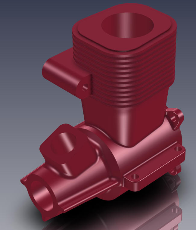
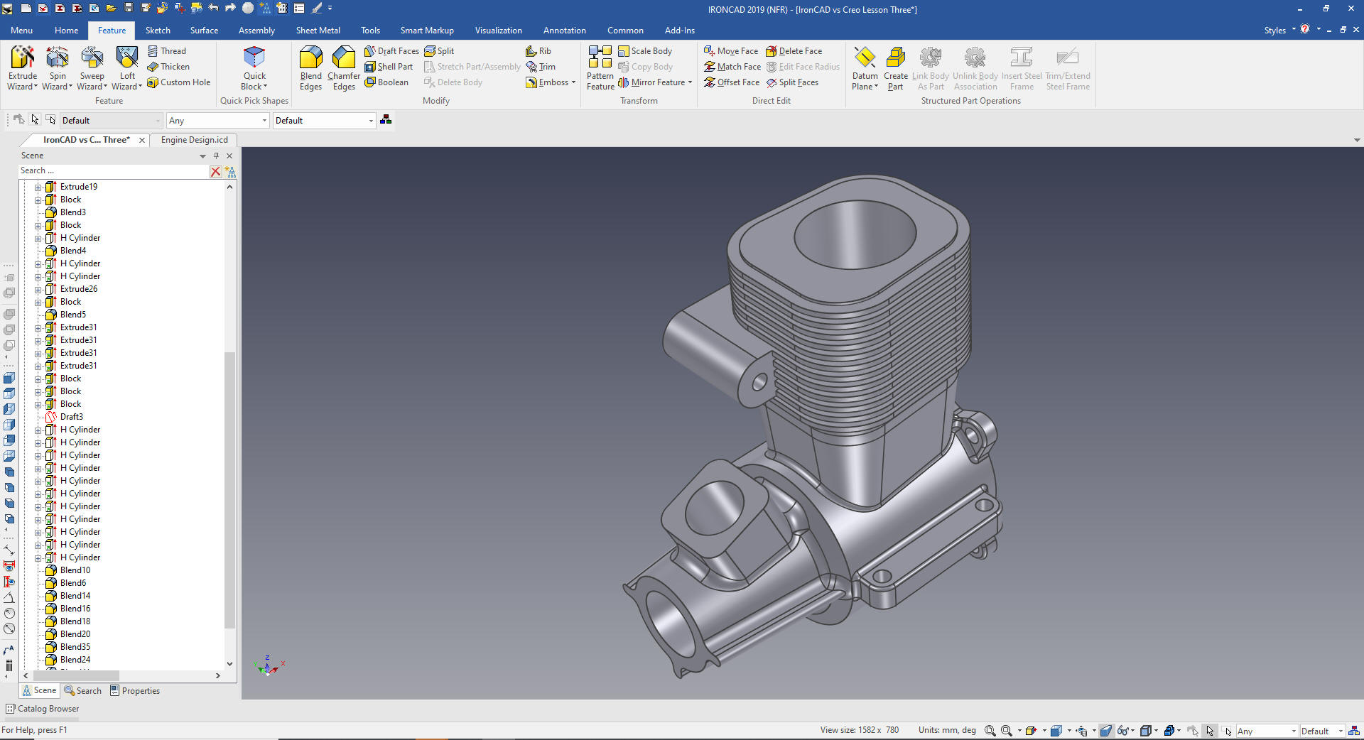
(Actually
this is a model airplane engine since is only 60mm (2.4 in))
While creating 3D models from drawings is the very best
way to learn 3D CAD and maybe some design techniques it does not
expose the designer to the design flexibility necessary in design. IronCAD is all top down due to the single model environment.
Creating mating parts is a cruise. But modeling is just one aspect of a
well designed productive 3D CAD system.
Solidworks
is a marginal 3D CAD system based on the dated Pro/e history
based modeling system released in 1988. I sold Pro/e years ago
and found it not productive enough
for our engineering department. We use what we sell. That gives us
the experience to effectively support our user base.
I would do a
video, but I really am not good at it. So I will show you step by
step. I will try and get IronCAD support to create one. They are
very good.
As with my Ironcad vs
Fusion 360 and other major CAD systems,
I have found the same problems with Solidworks. The modeling
technique is hugely responsible for the level of productivity. Those
of you that are only trained in the constrained sketching world are truly limited by not using the freedom of
Streamlined Sketching and Feature Based Modeling, that is available in even the most Solidworks-ish of CAD systems. If your
designers are designing in these very unproductive and time
consuming processes it might be time to review your standard design
processes. Don't have any do you?
As I watch the Solidworks user sketch this
part, I am amazed at the way he does it. I
just can't understand struggling with all the constrained
dimensioning. This IronCAD exercise took a few minutes and allows
for faster and much easier modification. Again these exercises turned
into a study of modeling techniques even though most of this model
is Feature Based Modeling not available to most of the Solidworks clones.
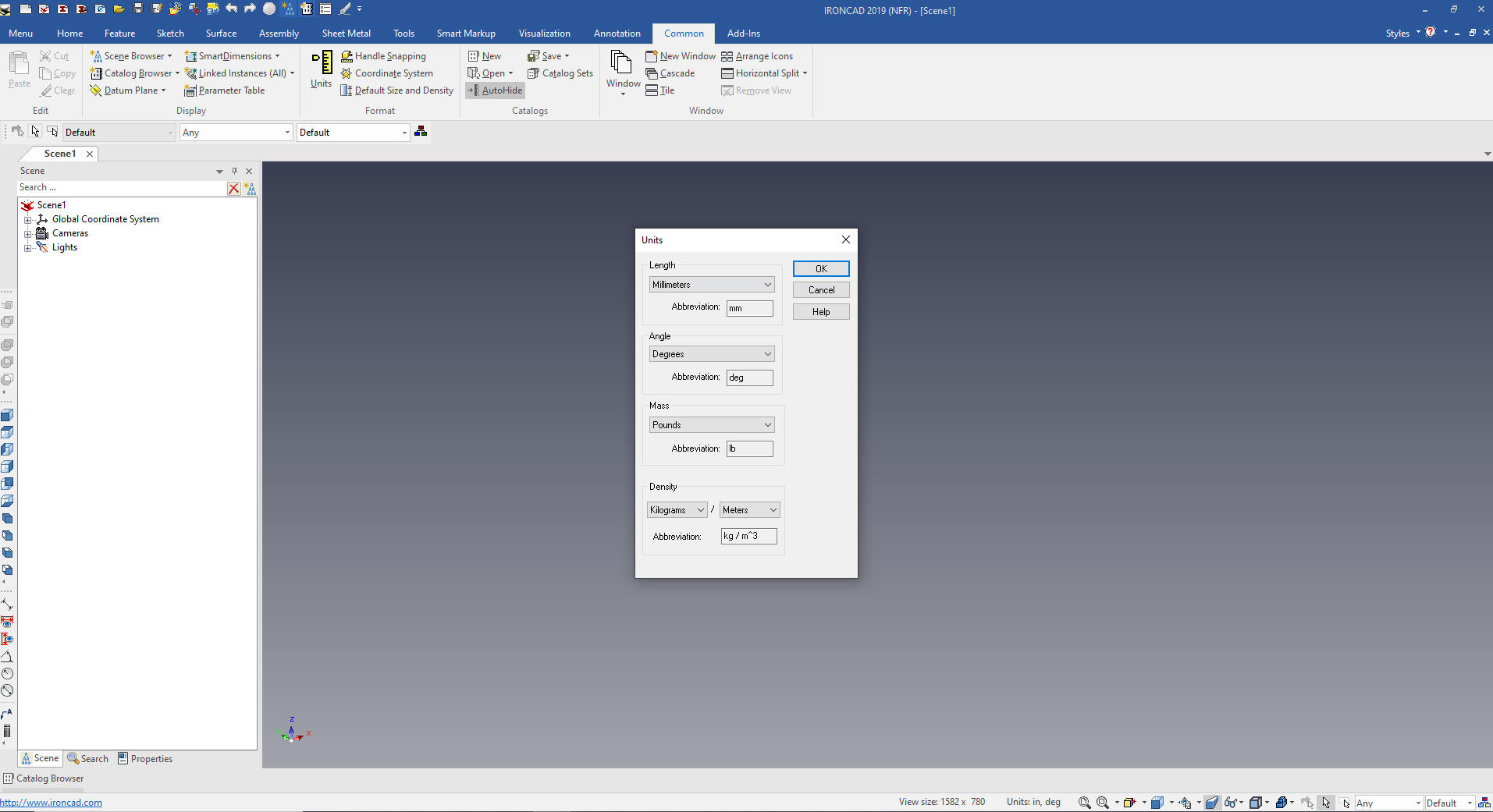
Here is IronCAD. My default is inches,
so we will set the units to mm. Let's get started.
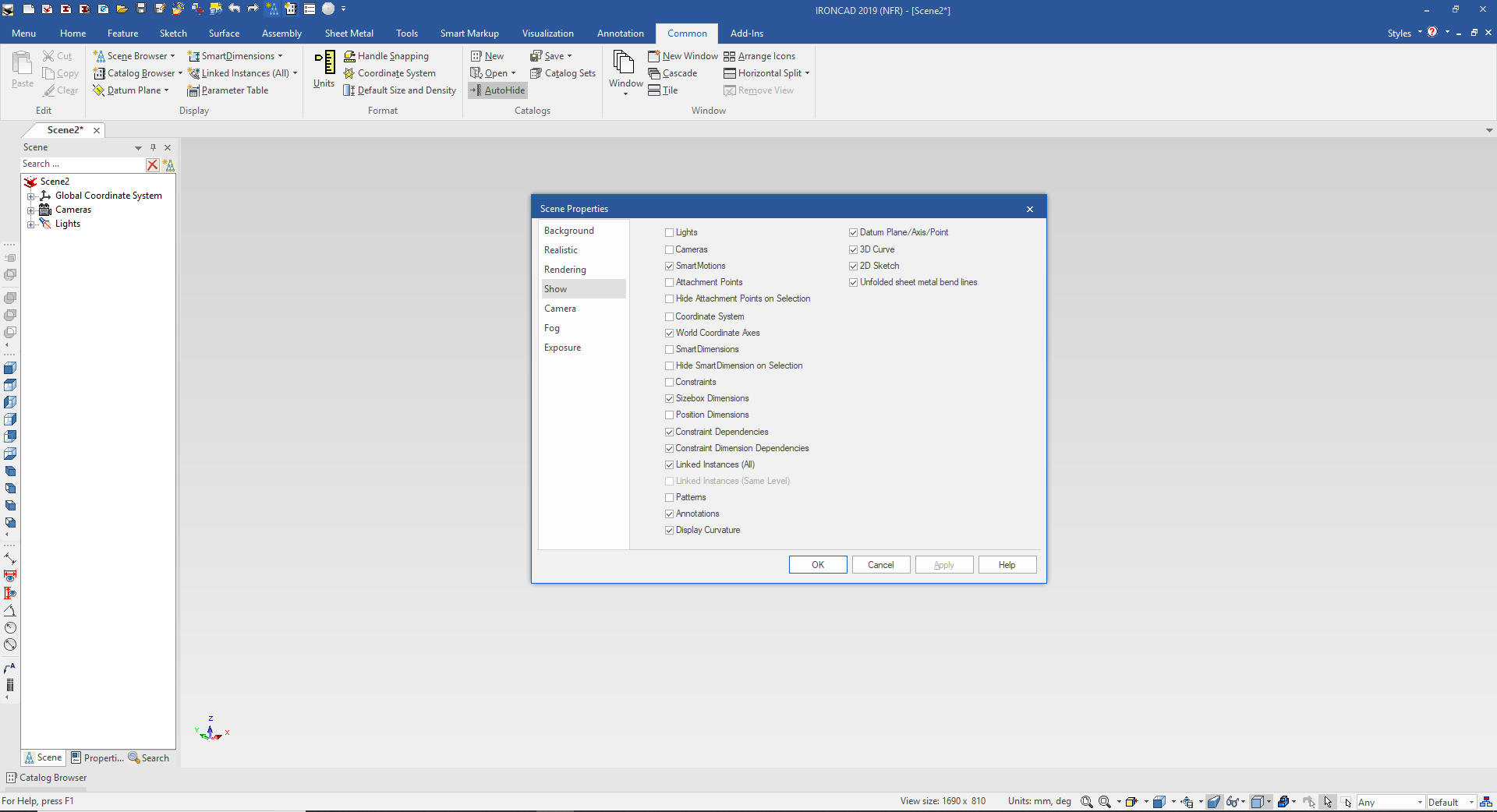
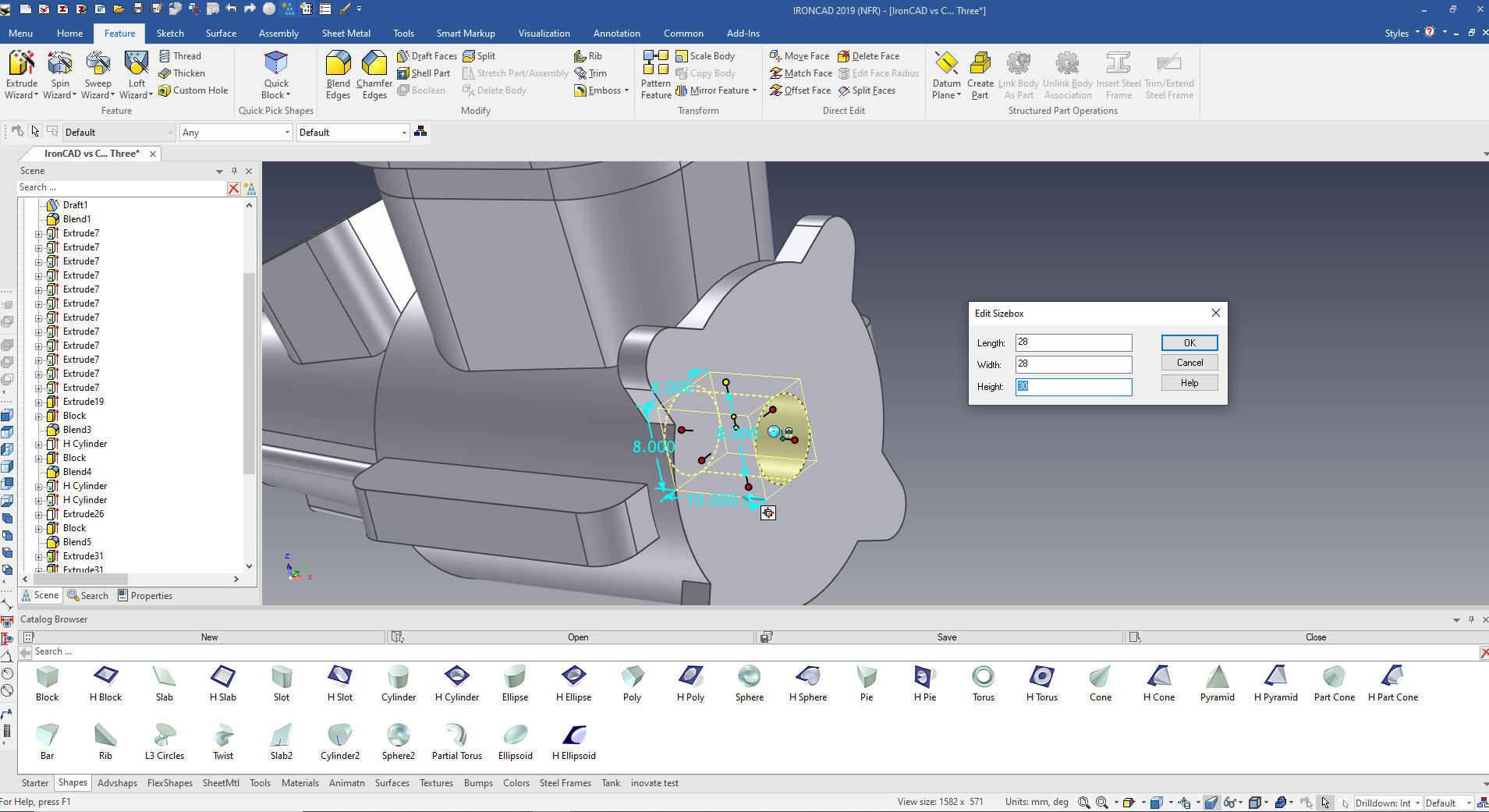
If you are following this tutorial. I
first select show the size box dimensions. You can save your custom
configurations if you want.
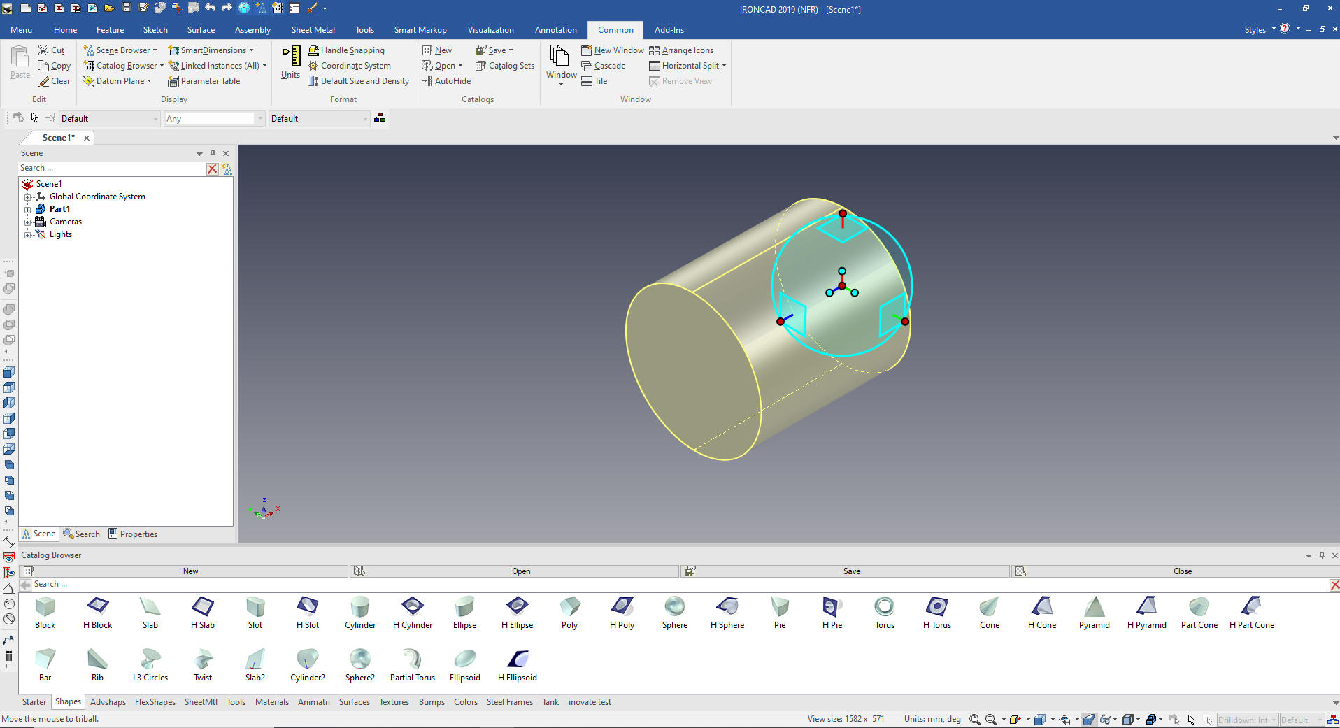
I
look at the part and I see a large cylinder and two cones for the
basic body. Yes I could easily sketch these by you already know how
to do that so I will drag and drop a cylinder from the standard
catalog into the scene, size it and adjust the position using the
Triball. It automatically drops at X0Y0Z0.
Note: Why does IronCAD
call it a scene instead of a workspace? IronCAD was first released
as a graphic design program called Trispectives. It still has much
of the graphic design functionality. It truly is a wonderful mixture
of professional 3D CAD and graphic design, which puts it in a much
more flexible category as compared to the very mechanical
engineering focused Solidworks clones.
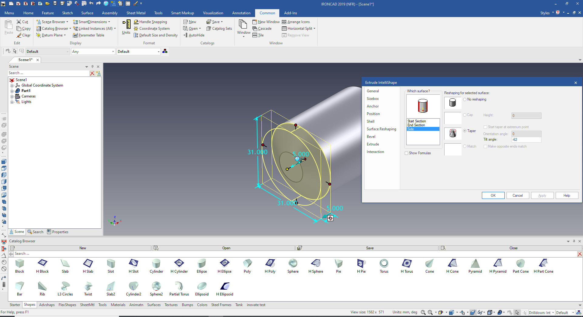
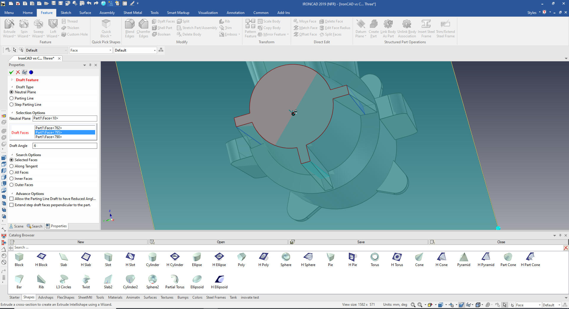
We drag and drop cylinder on the front
face of the existing cylinder, size it and using the Surface
Reshaping properties set the draft angle to 62 degrees
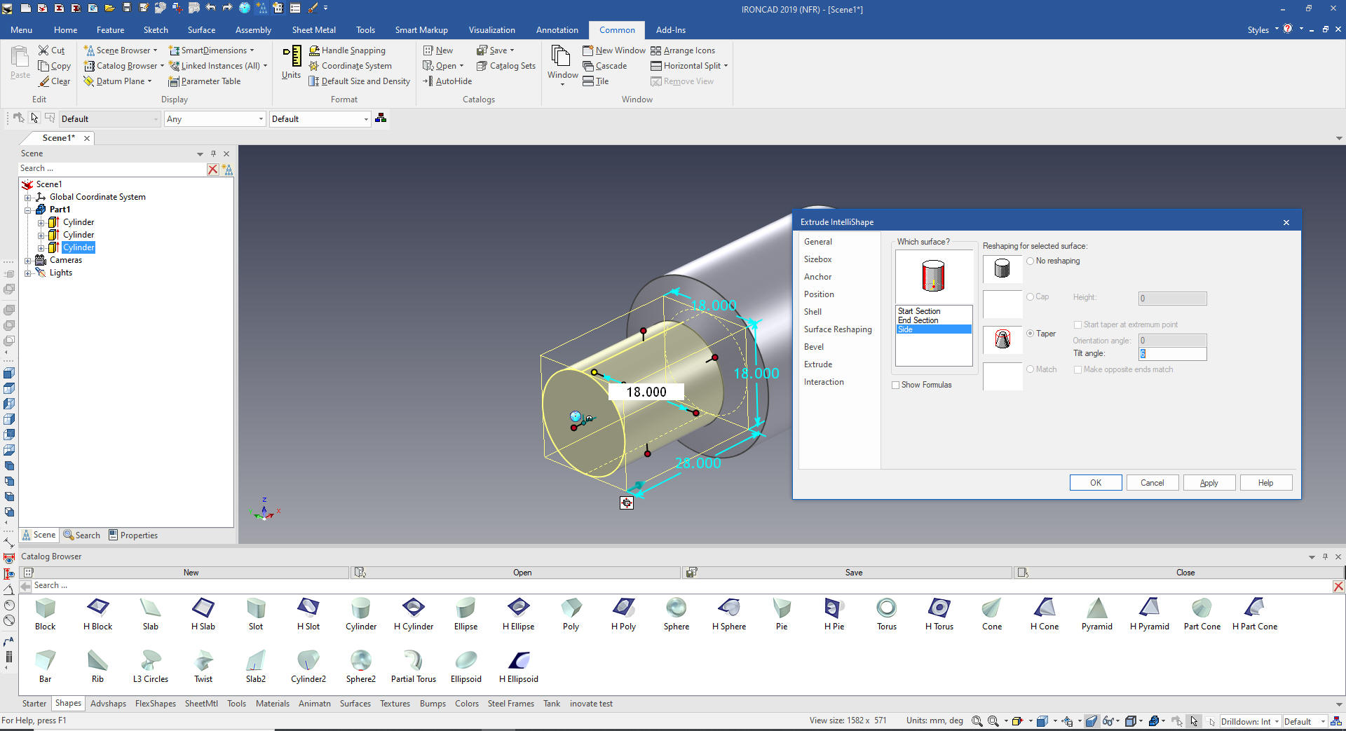
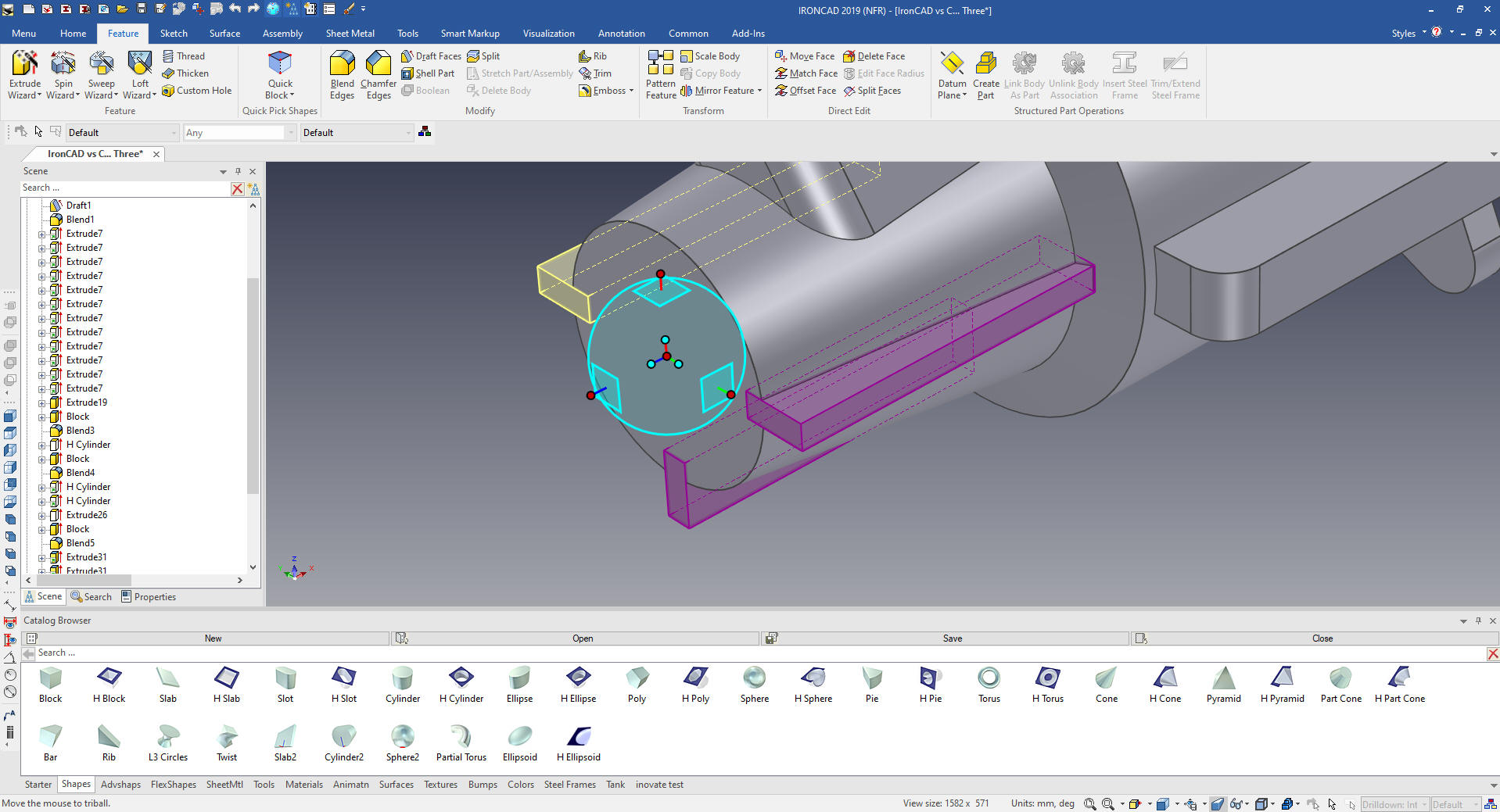
We drag and
drop another cylinder onto the face of the taper shape. We flip the
extrusion and set the location and size. Again we use the surface
reshaping tool to set the draft angle to 6 degrees. The poor
Solidworks
presenter is still fiddling with his sketch!
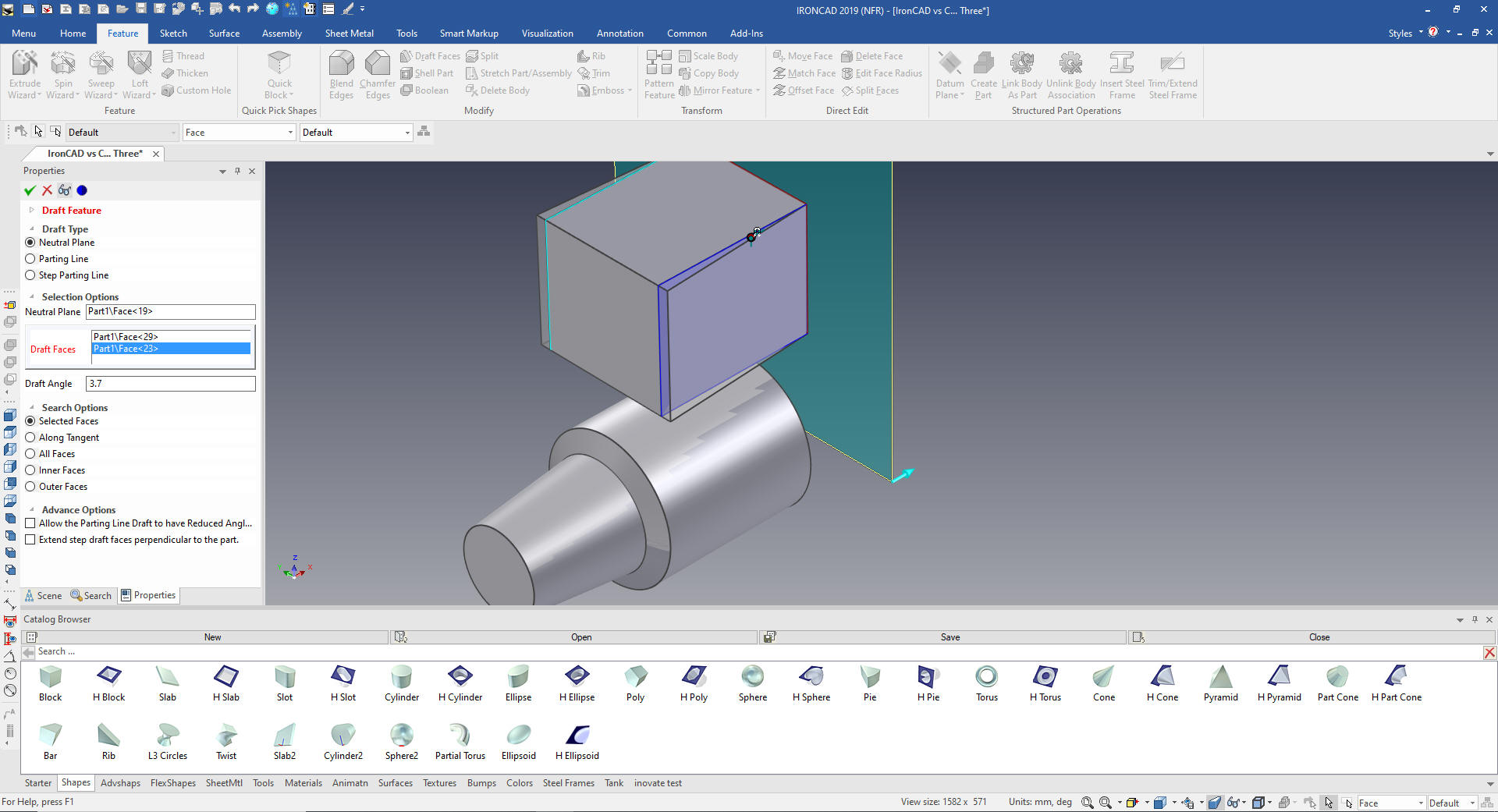
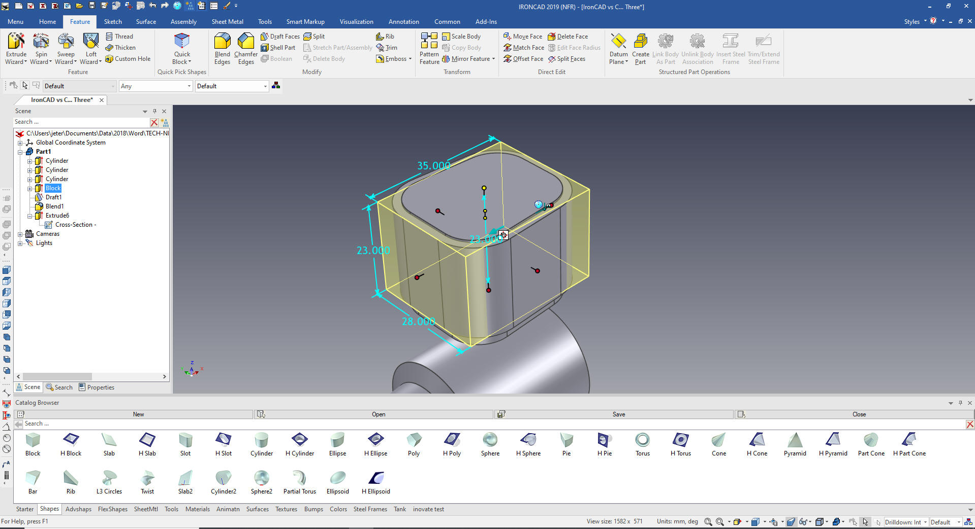
We have our
basic body. I drag and drop a block to the back face of the cylinder
locate by pushing and pulling the handle using existing graphics. I
put a 3.7 degree draft on the affected faces.
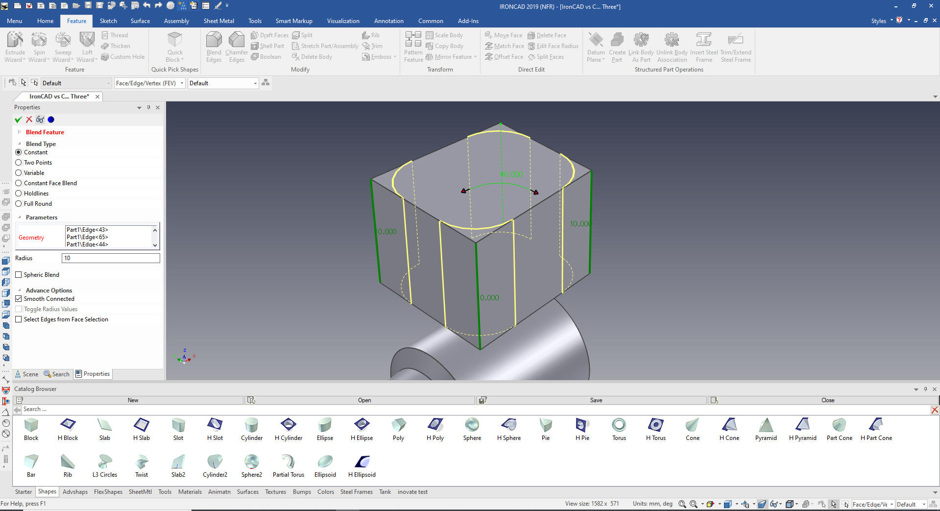
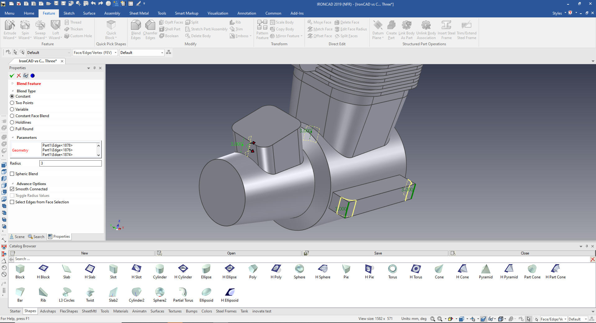
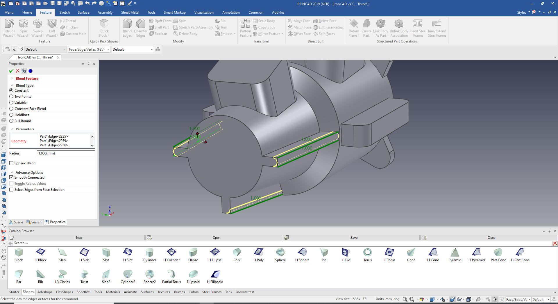
We put the
blends on the shape.
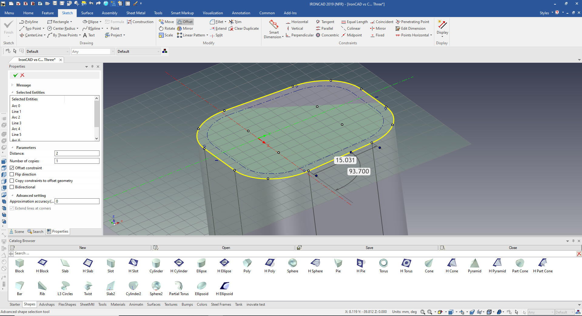
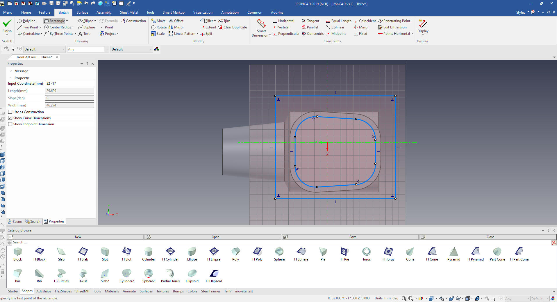
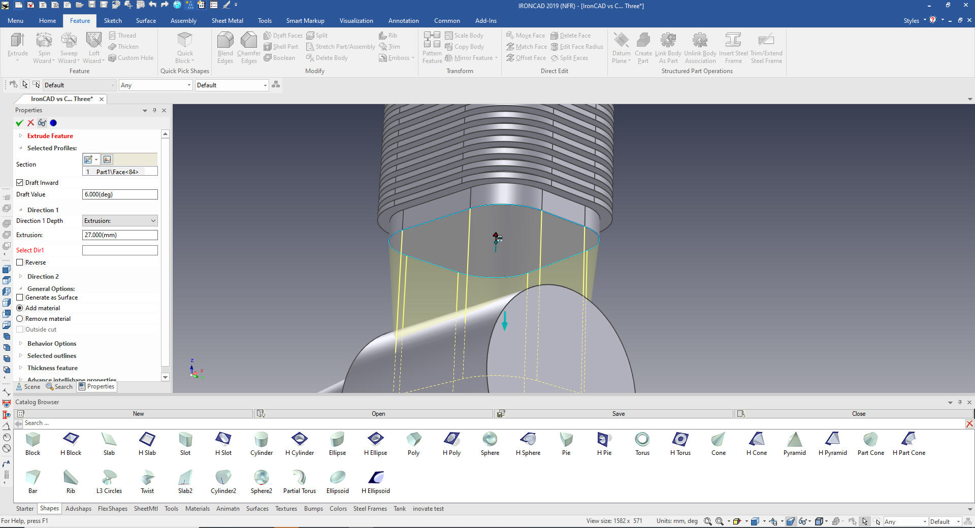
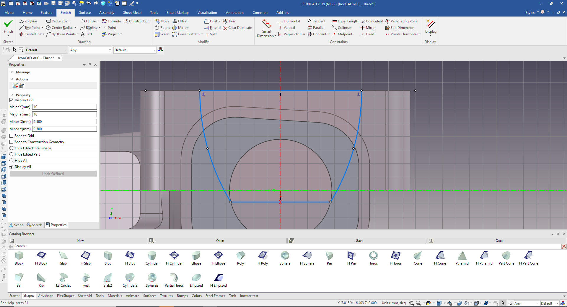
It is easiest to sketch the inner
shape and extrude it. We used the Extrude Wizard that immediately
creates the extrusion. IronCAD also has a stand alone sketch command
for working with complex sketches or importing .dxf or .dwg
We just project the shape and do an offset. I love the way IronCAD
leaves the original entities selected for easy deletions. IronCAD is
very focused on reducing steps for many of the functions.
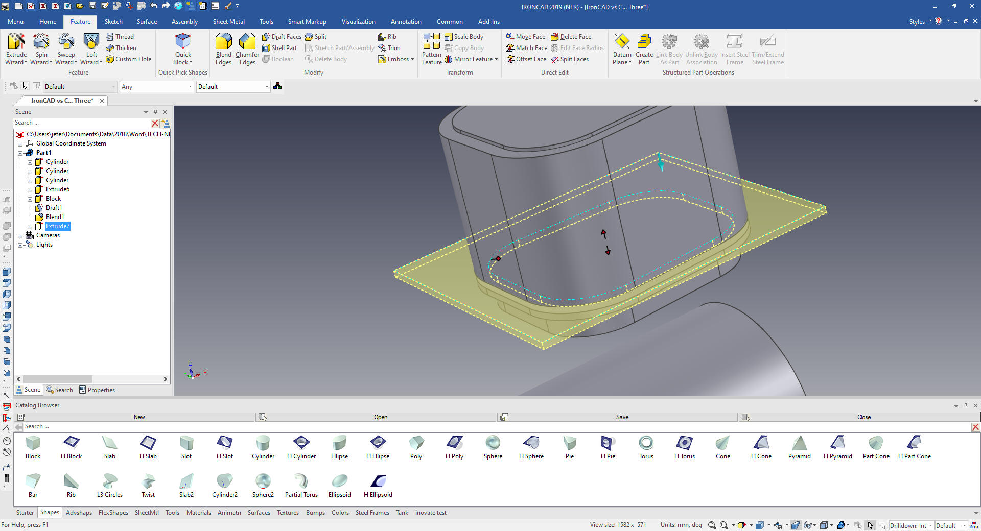
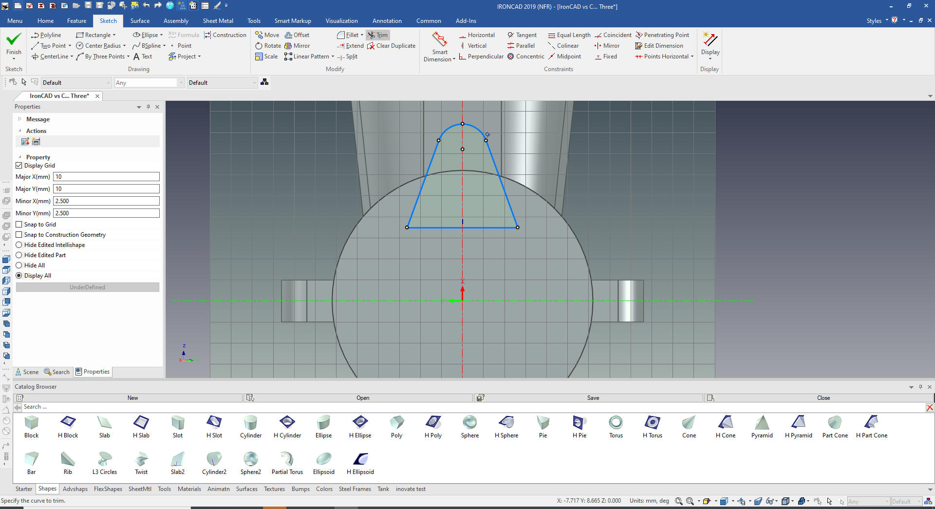
We set the size of the extrusion to
match the fins shape. We adjust the fin shape as required
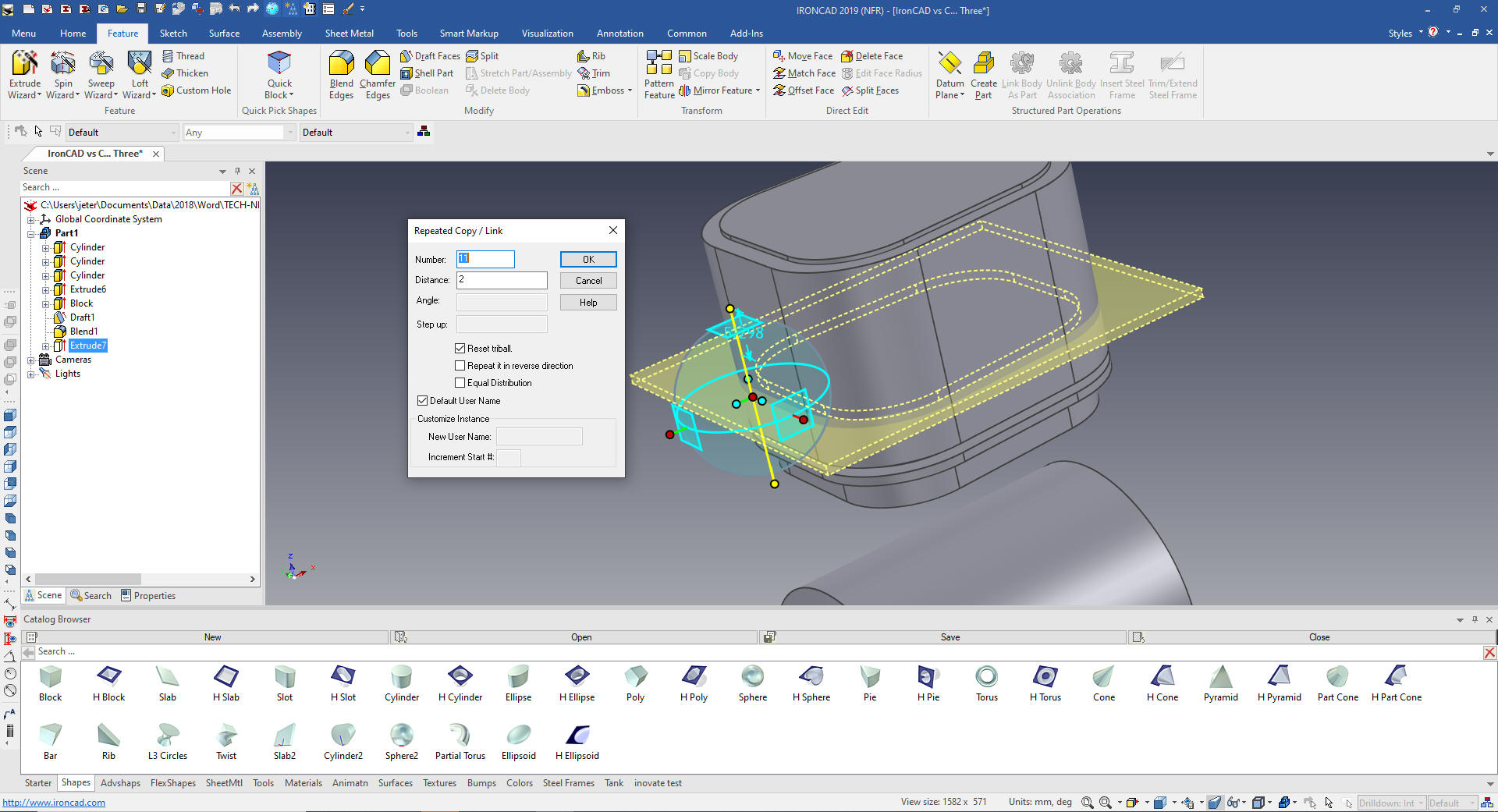
Again using
the Extrude Wizard we create the fin cut.
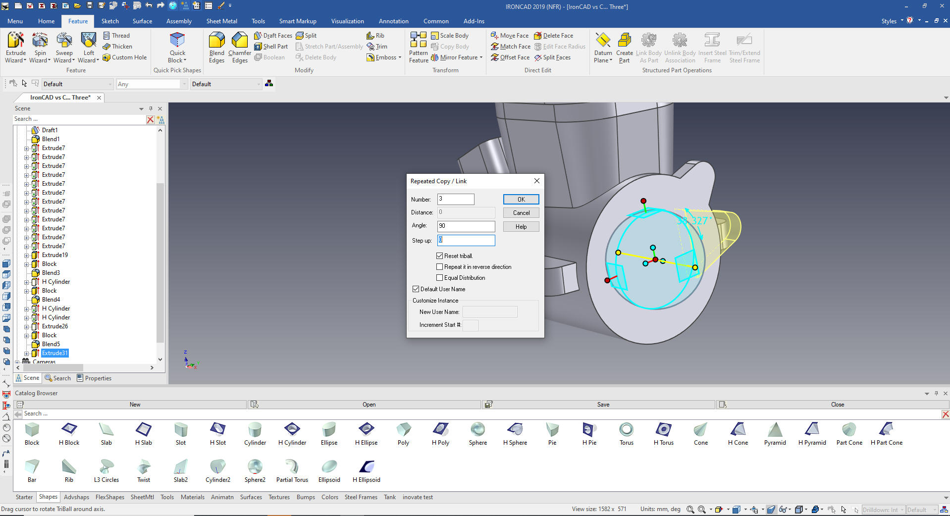
We pull it
into place and size it.
We use the
Triball to copy link the cut. You can see IronCAD can offer many
different ways to model.
I will use the Extrude Command. Select
the bottom face set the height and 6 degree draft.
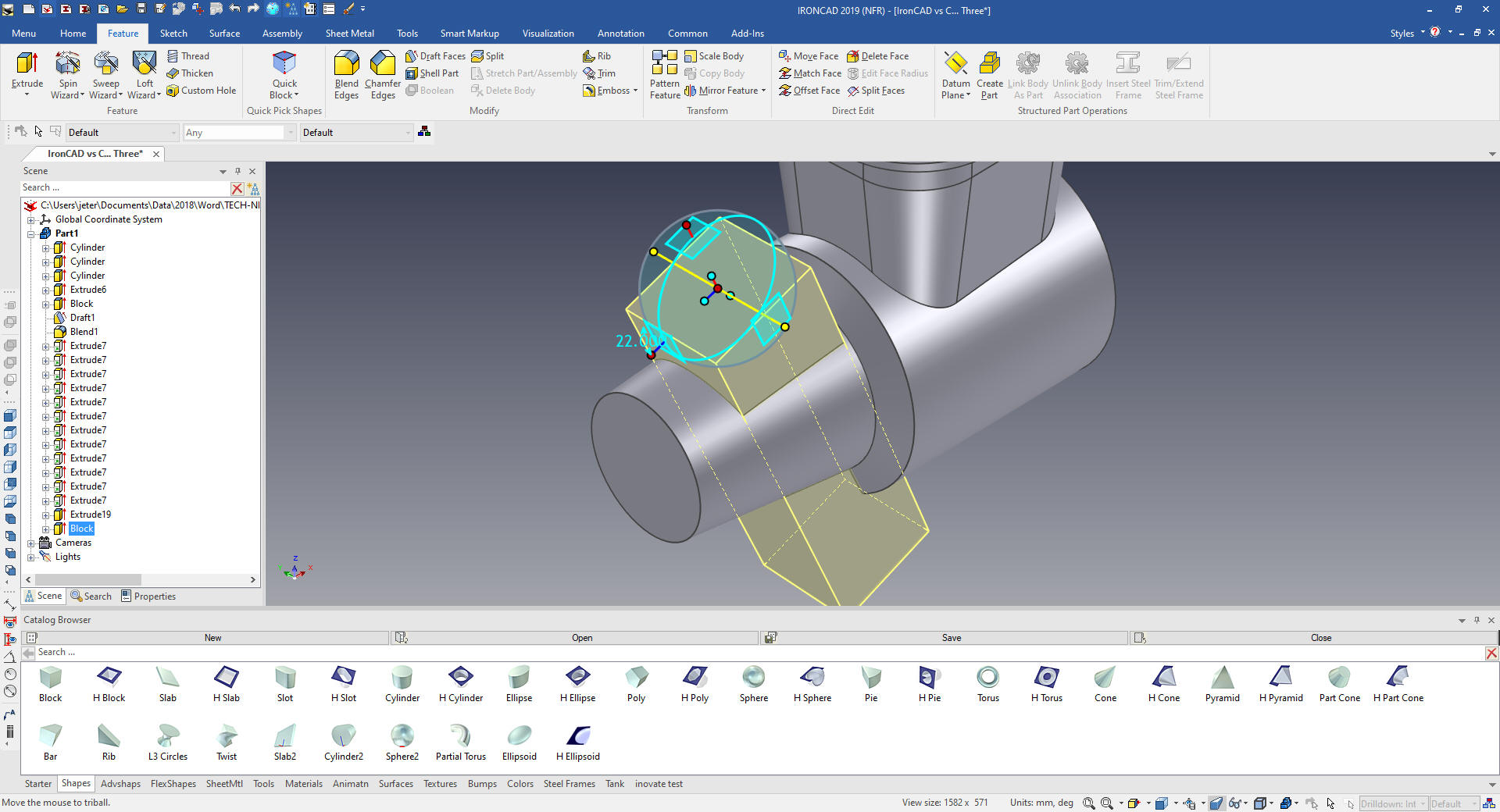
I
drag and drop a block to the face of the front cylinder and size it.
I move the Triball the center of the block (You disassociate the
Triball by hitting the spacebar). You then move it to the correct
locations. I move the location from inside the cylinder to outside
for inspection purposes. I round it off since the location is
probably arbitrary within a few mm.
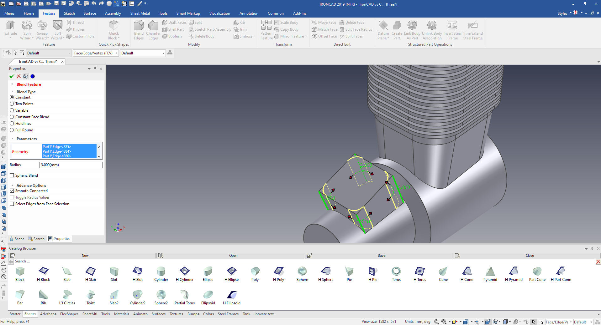
I
pull the block within the cylinder and add the blends.
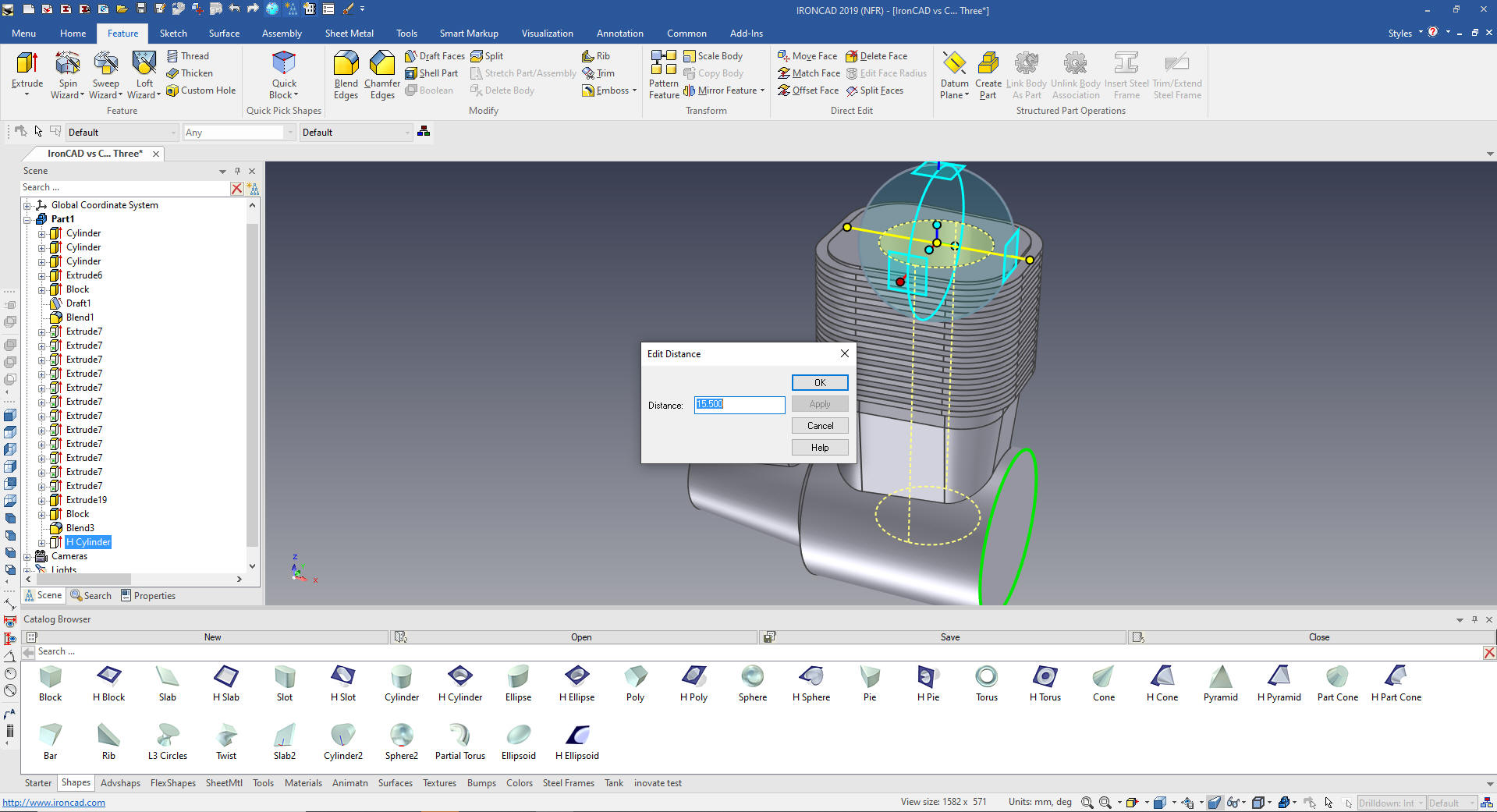
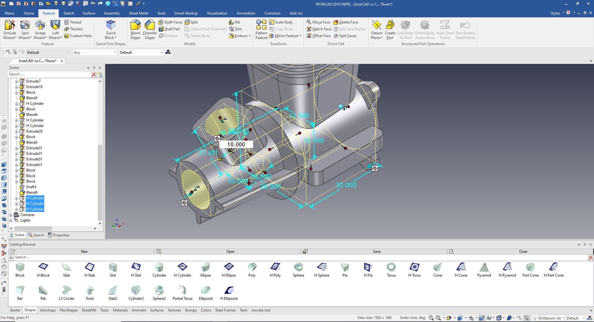
We
will now put in the piston cylinder, size and locate it, since the
next shape will be referenced from it. I set the Triball in the
center of the cylinder and select the relevant axis to set the
distance from the main cylinder.
The Triball has many
functions for manipulating features, sketches, parts and assemblies
due to IronCAD's single model environment.
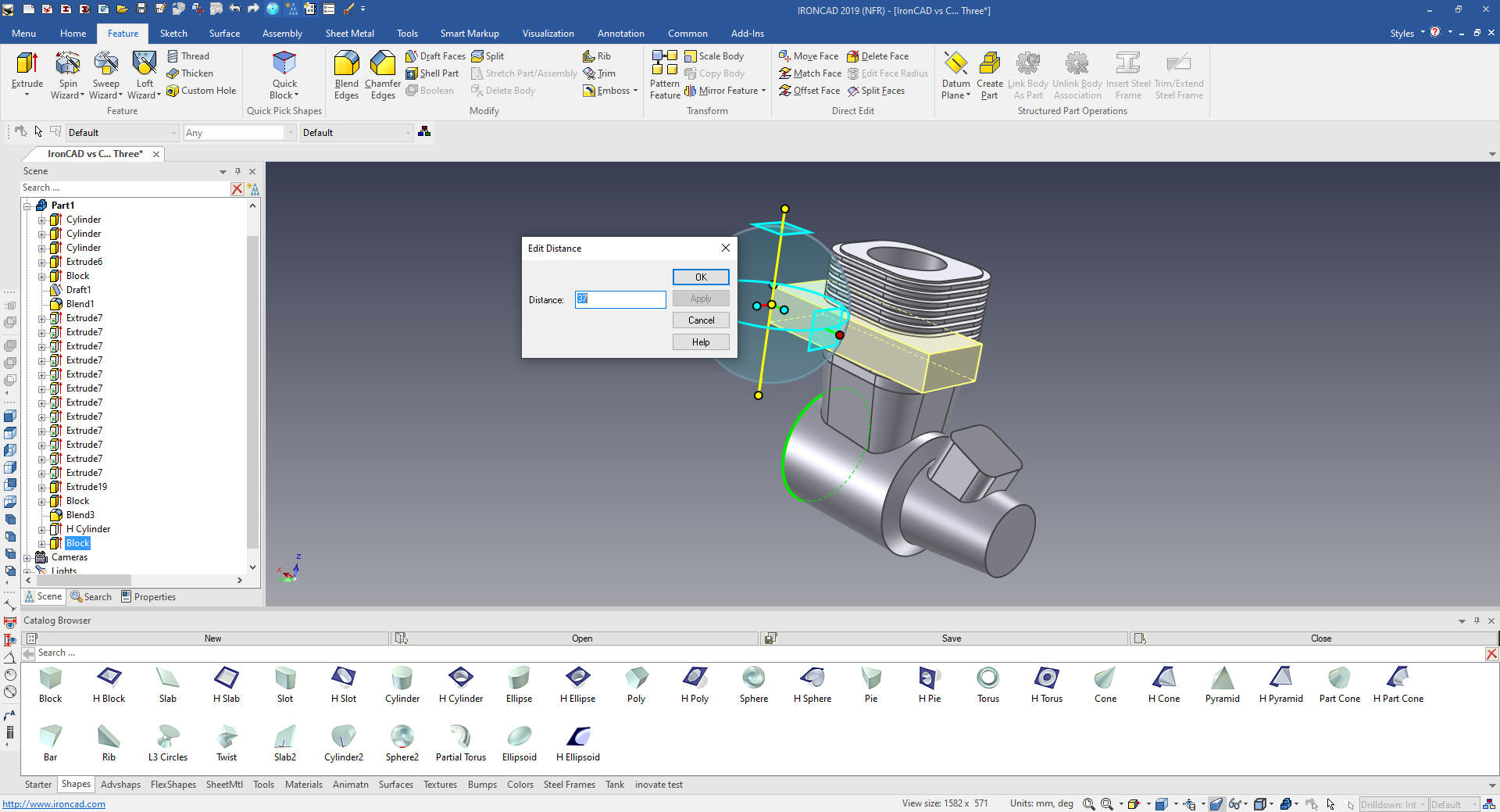
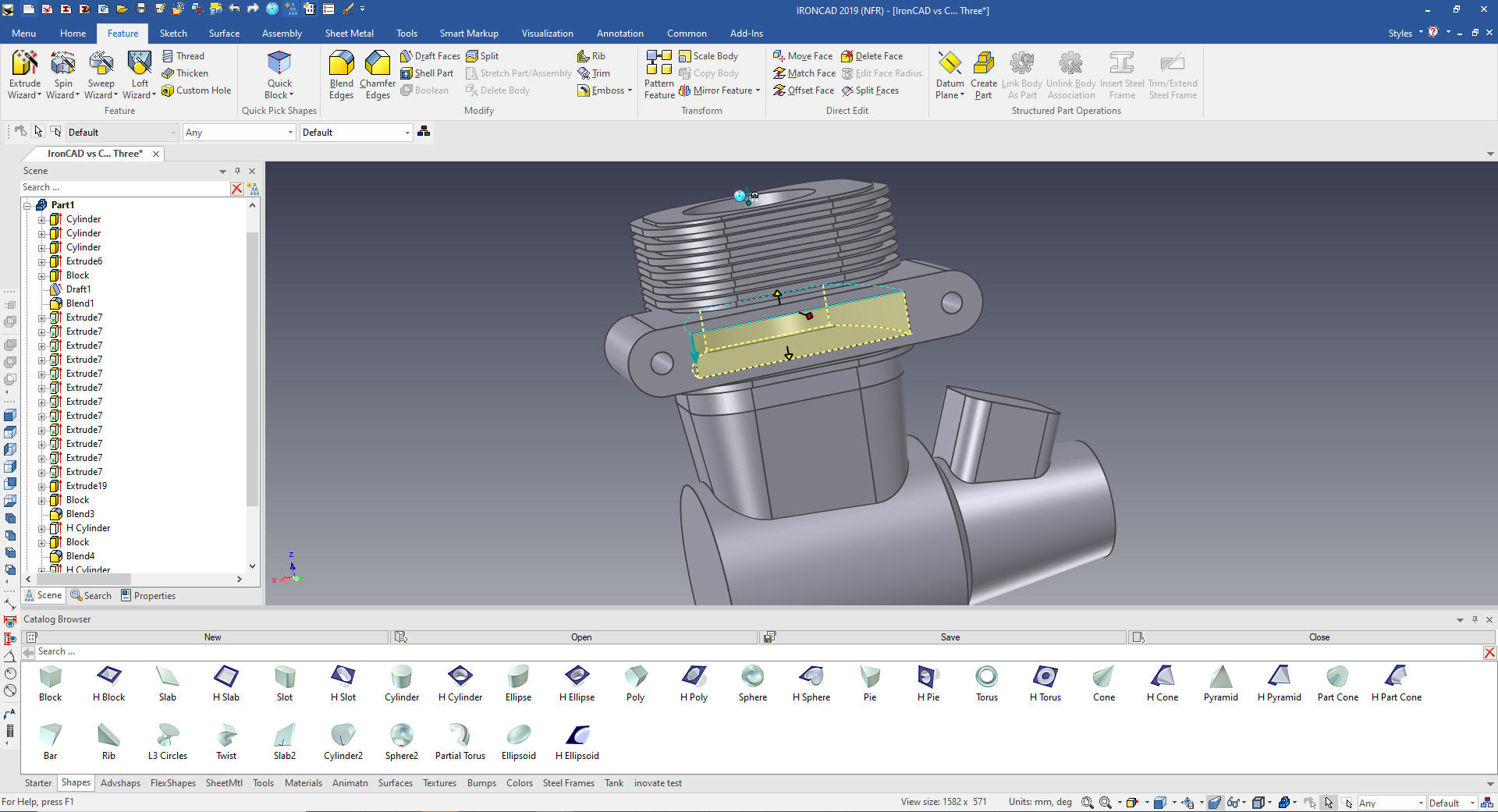
We
create the exhaust block by dragging and dropping a block on to the
top face, pulling it into shape. Then with the Triball we locate it.
We could use push and pull to also do it but since it was to the
center I opted for the Triball
This is one of the most stark examples
of how IronCAD's drag and drop of editable shapes from a catalog and
the use of the Triball can increase productivity 10X in this case. I
usually estimate 5X increased productivity in conceptual design and
10X in changes, and I believe I am being conservative. IronCAD can
edit most of the Solidworks clone parts and assemblies faster than it
can be done in the native CAD system.
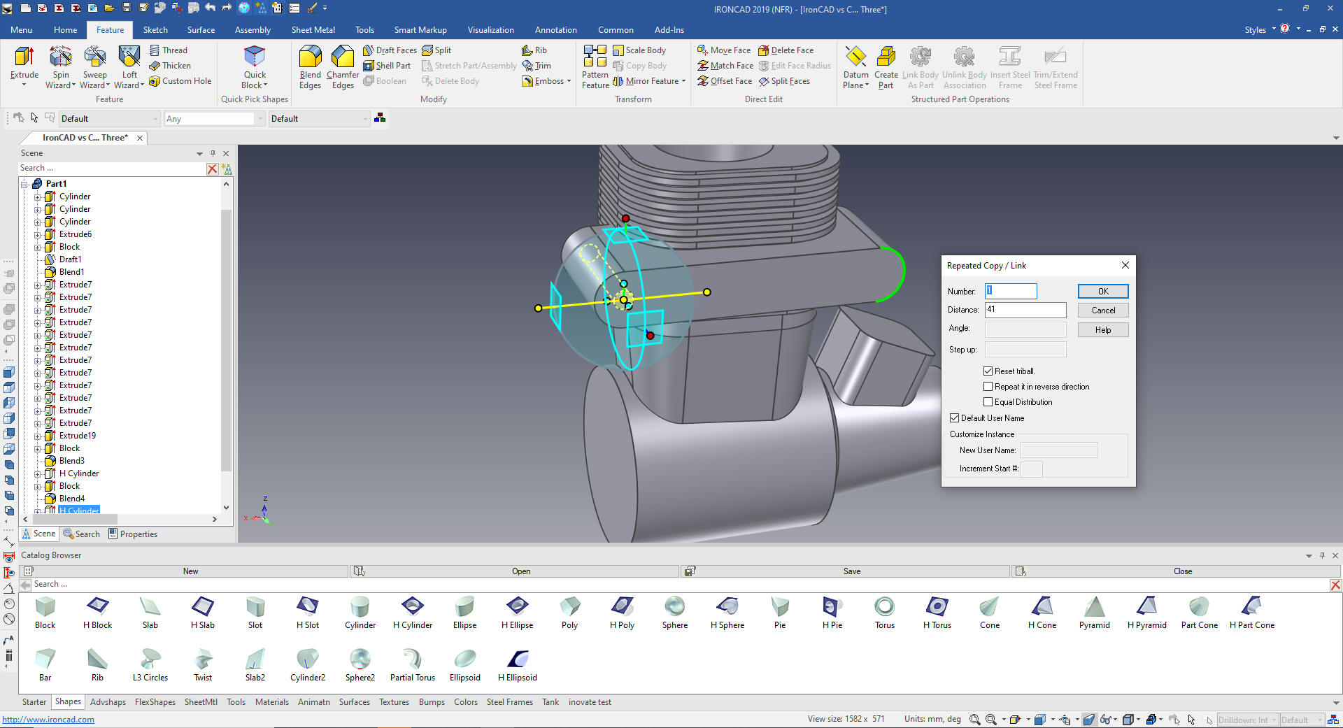
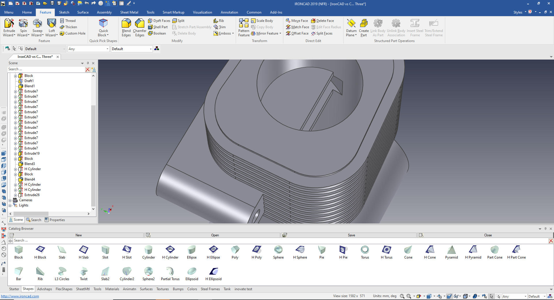
We create the blends on the edges of
the block and drag and drop a hole cylinder to the center of the
radius then link copy with the Triball.
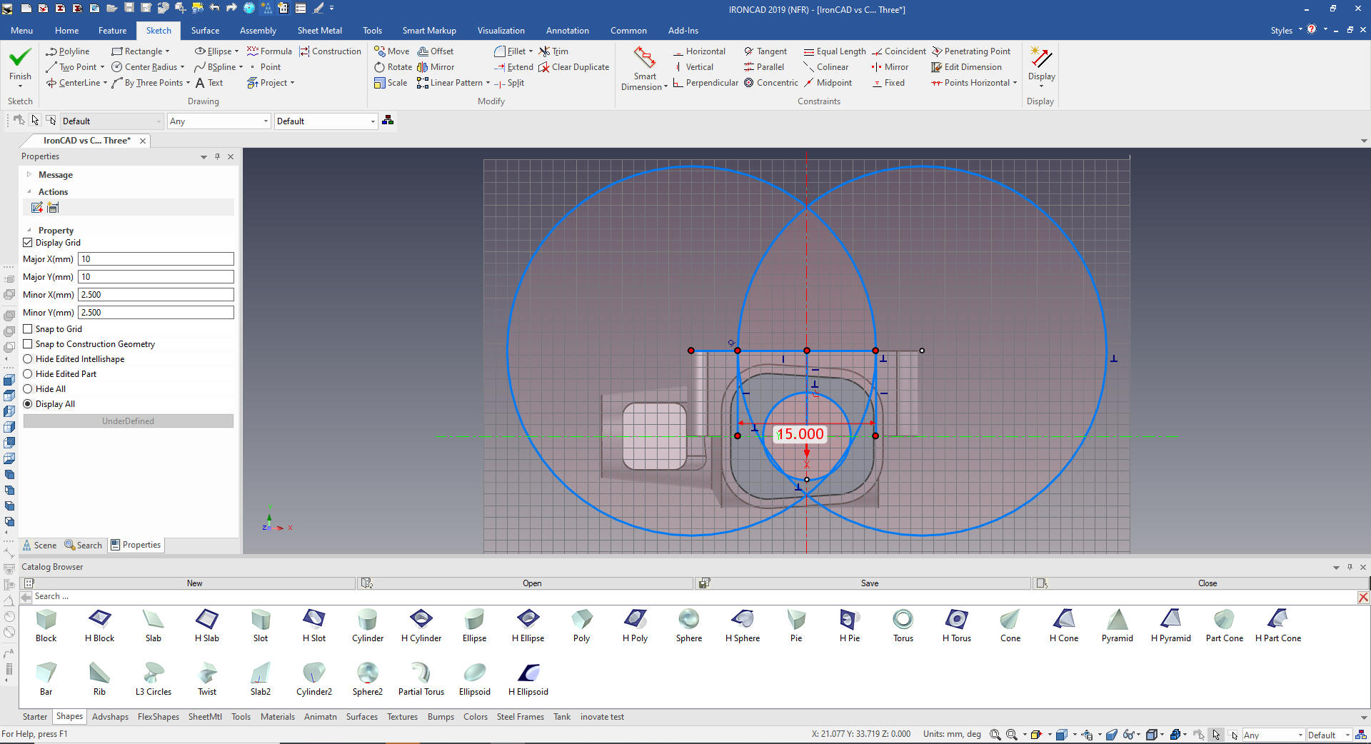
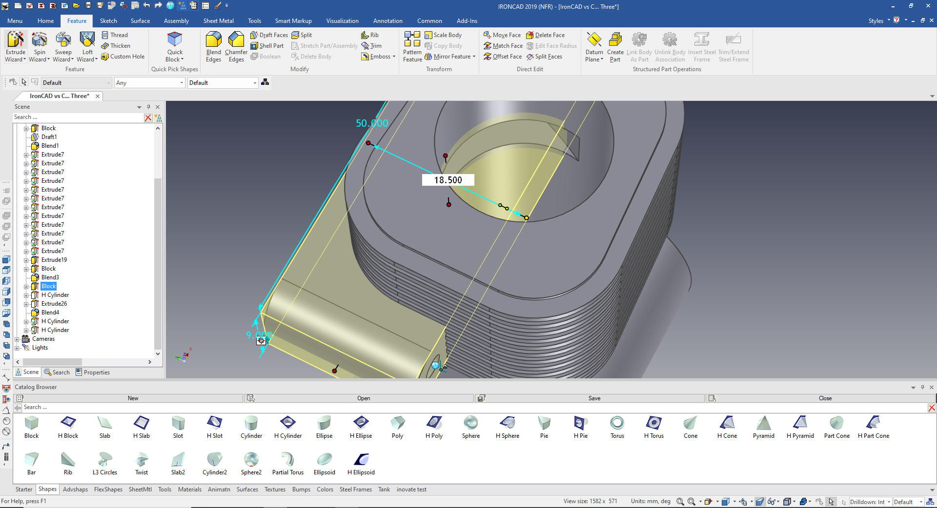
Using the Wizard we create sketch on the
top of the cylinder block. We create the basic graphics to define
the cut.
Trim or extent to get the net profile.
Using the
handles we pulling the faces into the correct location.
As you can see
I have made the exhaust block after the piston cylinder an we have
to position the block before the piston cylinder.
We just move the block before the
cylinder and all is correct. Since the shapes are not based on
defined planes and sketches you have much more freedom in your
history.
Now for two side pieces. We drag and
drop a block to the top face pull it to size and locate it and add
the blends
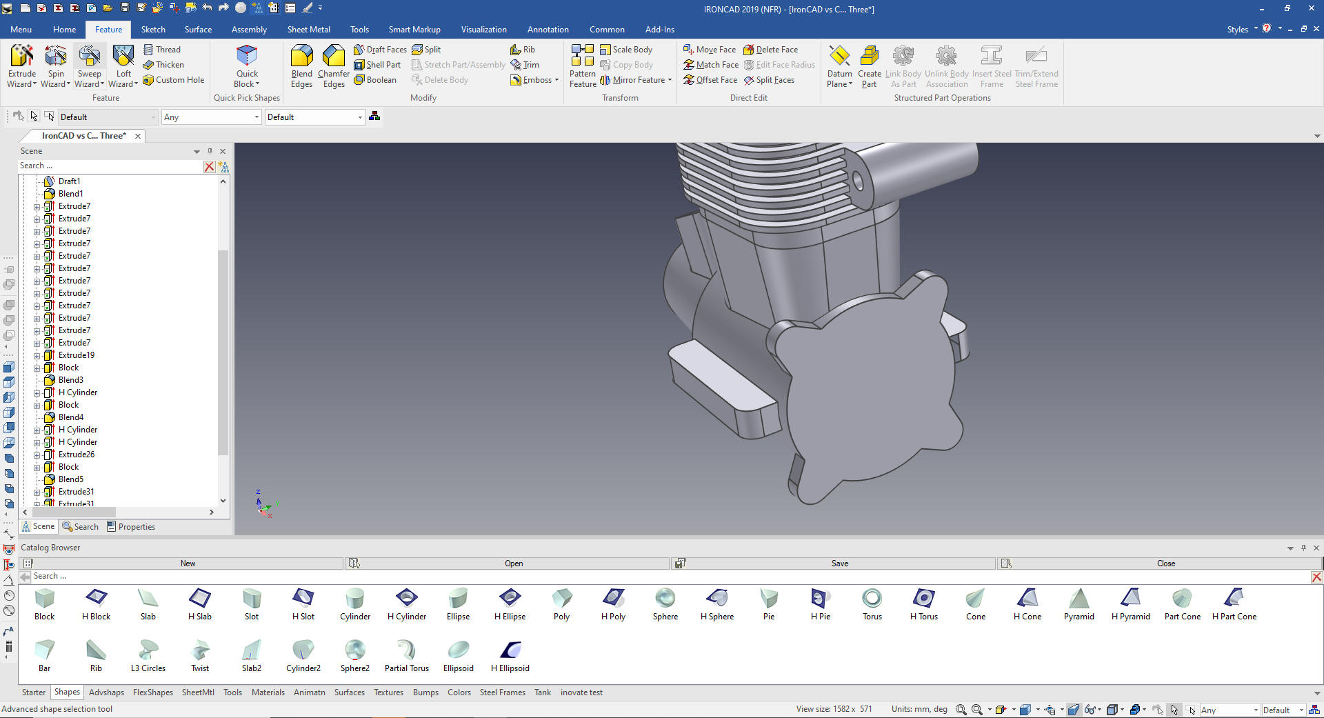
Now
for the mounting tabs. Using the extrude wizard create a sketch, you
can see we do not do any constraining.
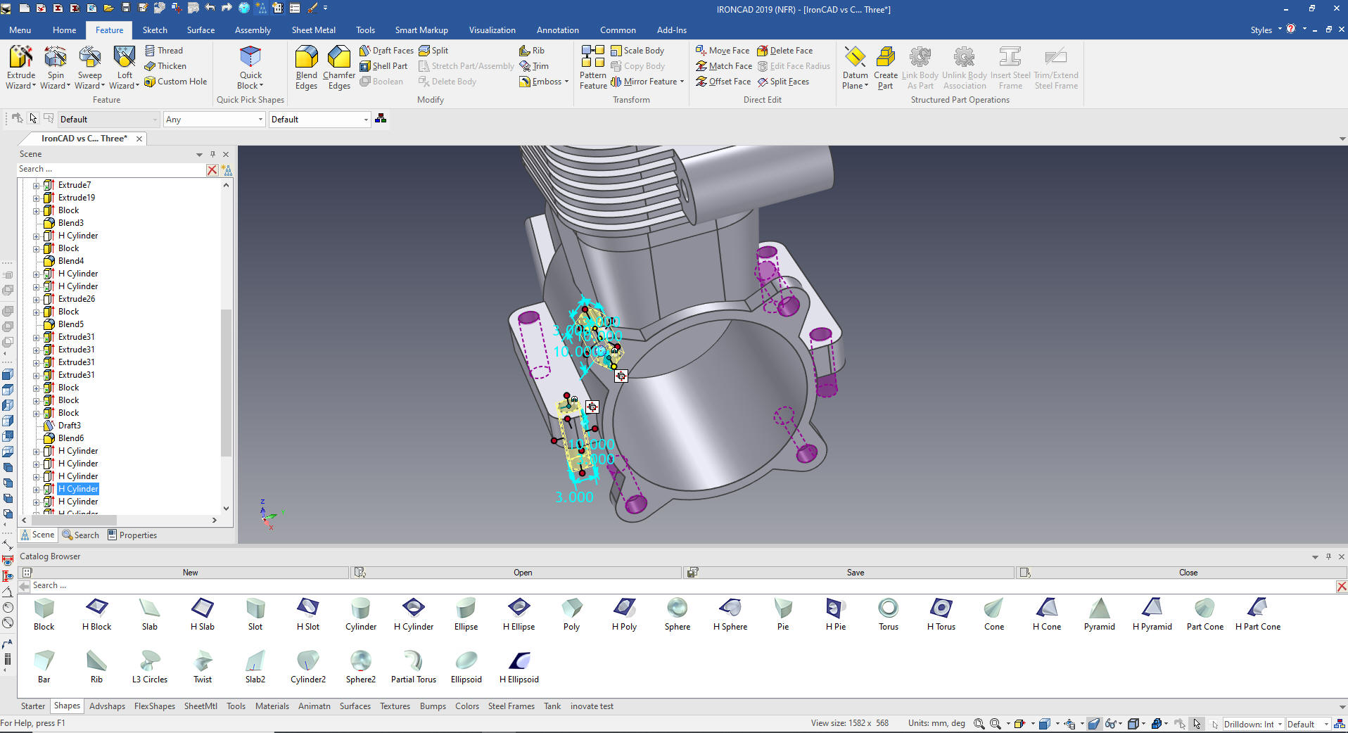
Using
the Triball we rotate the feature, then link copy the other 3 tabs.
Now
the front ribs. We just drag and drop a block locate and size it.
Using the Triball we rotate copy link the other two. The purple
indicates that there are other link shapes tied to this shape.
We draft the faces 6 degrees.
We
add the 1mm blends to the ribs.
We
just create the first hole by dragging and dropping a hole cylinder
to the center of the main Cylinder face.
Now for the rest of the large holes.
A few more holes.
Now for the work, putting in the blends
and we are done!
Give me a call if you have any
questions. I can set up a skype or go to meeting to show this part
or answer any of your questions on the operation of IronCAD. It
truly is the very best conceptual 3D CAD system.
If you are interested in adding professional
hybrid modeling capabilities or looking for a new solution to
increase your productivity, take some time to download a fully
functional 30 day evaluation and play with these packages. Feel free
to give me a call if you have any questions or would like an on-line
presentation.