|
The Integrated AID (Drawing) in 3D CAD A Solution for the PDM Nightmare! |
 Update 9-4-19 I have been doing some comparison lessons with other CAD packages. Here is one with a Catia 10 part assembly. Catia created 30 files, 10 parts, 10 AIDs (drawings) and 4 sub-assemblies, 4 sub-assembly AIDs (drawings), 1 top assembly and 1 top assembly AID (drawing).  ZW3D vs Catia Lesson 3 Assembly 3D Modeling Techniques Defined True Top Down Assembly & In Context Design versus Separate Part Design
Can you imagine a large manufacturing company like Boeing? No PLM or PDM system could handle this amount of documentation effectively. ZW3D with its Multi-Object environment did this in one file. But what if we did these in separate files instead of the Multi-Object environment, you still reduced the file count by 10! How convenient is it to have the AID (drawing) in the same file? It is worth changing CAD systems! Even if you use PMI (which is included in ZW3D) you have added documentation available to support the part or assembly. Actually, that is why the PMI was created to have one design file. Sadly, it is by far the worst engineering document with virtually no standards! The Integrated AID (Drawing)
There are a few 3D CAD functions that are not readily available with a Pro/e
Clone. These are so productive that each one alone can increase your
productivity by 2X. There are basically Three. Which the article topic is last. 1. The Single Model Environment This is by far the most productive 3D system environment feature. Only a few systems have this. You design in-context or top down by system design. It is the only design process you use. I was talking to a very experienced Solidworks user and engineer. I was discussing the weakness of bottom up design, being done by so many Solidwork’s users. He said he designed that way. Well, I sold him a seat of ZW3D. I showed him he didn't have to do PDM in the conceptual phase of the project. He saw that he could do the all of the part and assembly design and the integrated drawing in one file as a complete project. 2. Integrated History/Direct Edit This is the next required functionality. There is no
substitute. The need to do extensive design intent before starting a part is
wasting a huge amount of design time. If you don’t do it (which is the sign
of an inexperienced user), it will put you in a corner every time. Imagine
just start designing your part, knowing you can just keep on designing no
matter what design problem you run into. There is even more productivity by
adding Hybrid 3D CAD modeling. This closes the door on any limitation by
having all of the design processes available: 2D/3D wireframe, free form surfacing and
history/direct edit solid
modeling.
3. Now to the Integrated AID (Drawing)
There is no place where the integrated AID (drawing) is not a more productive
feature! We first have to redefine the misnomer "drawing". We do not create drawings we create AIDs (Associated Information Documents). We create our AIDs by placing different related views of the model in a documentation or AID module and add dimensions and annotation. So we really have an integrated AID.
Engineering Ignorance Defined IV I have always had the
integrated AID (drawing) available. First in CADKEY and now in ZW3D. Just think of
the convenience of having the drawing in the part file. You just look to see
if there is a drawing in the same file. Most engineering is done in small project or assemblies. With these features you do the complete design project in one file. It is quite bizarre with those programs that have
separate drawings that they don’t even have a link to the drawing file from
the part or assembly file. How would a new user know it even exists without
knowing it exists. So what does the integrated AID (drawing) solve? Well, PLM would probably not have needed to be created. I know for sure we would not need MBE/MBD and the PMI. While this is probably marginally handled with a small company. Building large assemblies like Airplanes it is totally unmanageable or not cost effective. It opens the door to Murphy on so many levels. So, look at your own PDM and see the mess. Look how much it is costing you. Do you need a staff of IT folks just to maintain your engineering documentation? Is using Creo (Pro/e), Catia 5, NX, Solidworks or Inventor generating massive data?
Then think of all the parts that are interrelated. The biggest advantage and the biggest weakness of the
Pro/e clone is the associativity. This promise alone has not delivered and caused chaos in document control This is a no brainer for individual designers doing
single projects. Even in large manufacturing companies many single
projects are given to engineers. If you have concurrent projects where you have multiple
designers working on an assembly. The documentation (drawing) being integrated is a
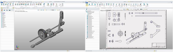
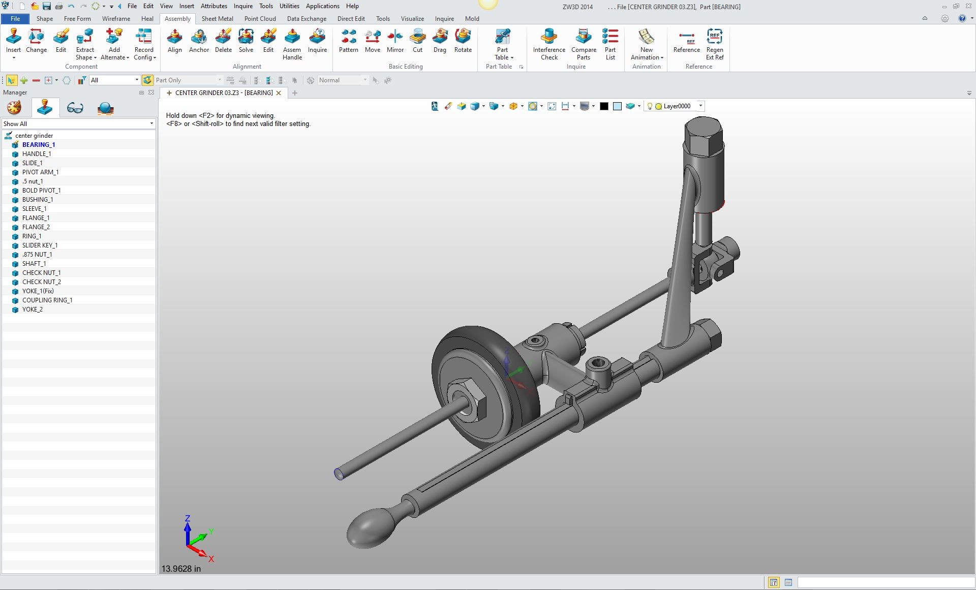
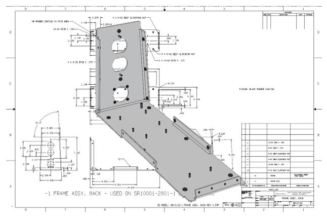
just another file that doesn’t need to be maintained. So, let’s see how this works. Here is our assembly. Now notice this is in a single file.
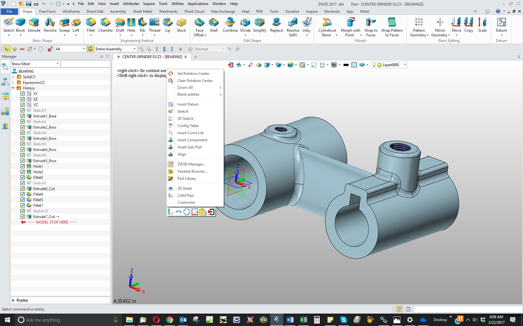
We will open the bearing. 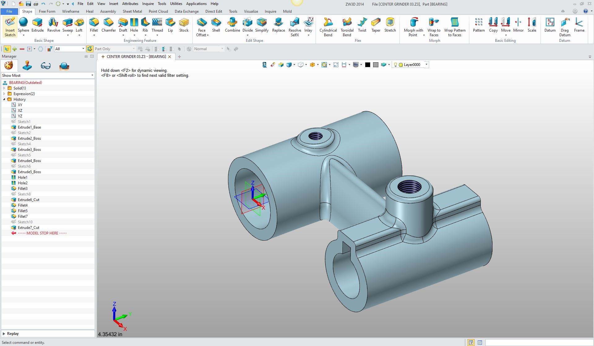
Then put the curser in the workspace and push the right mouse button and a
menu will show up and we will select 2D sheet.
Now, I have already created this sheet. But it is no
different than what you are already using except it is integrated into the
part or assembly. 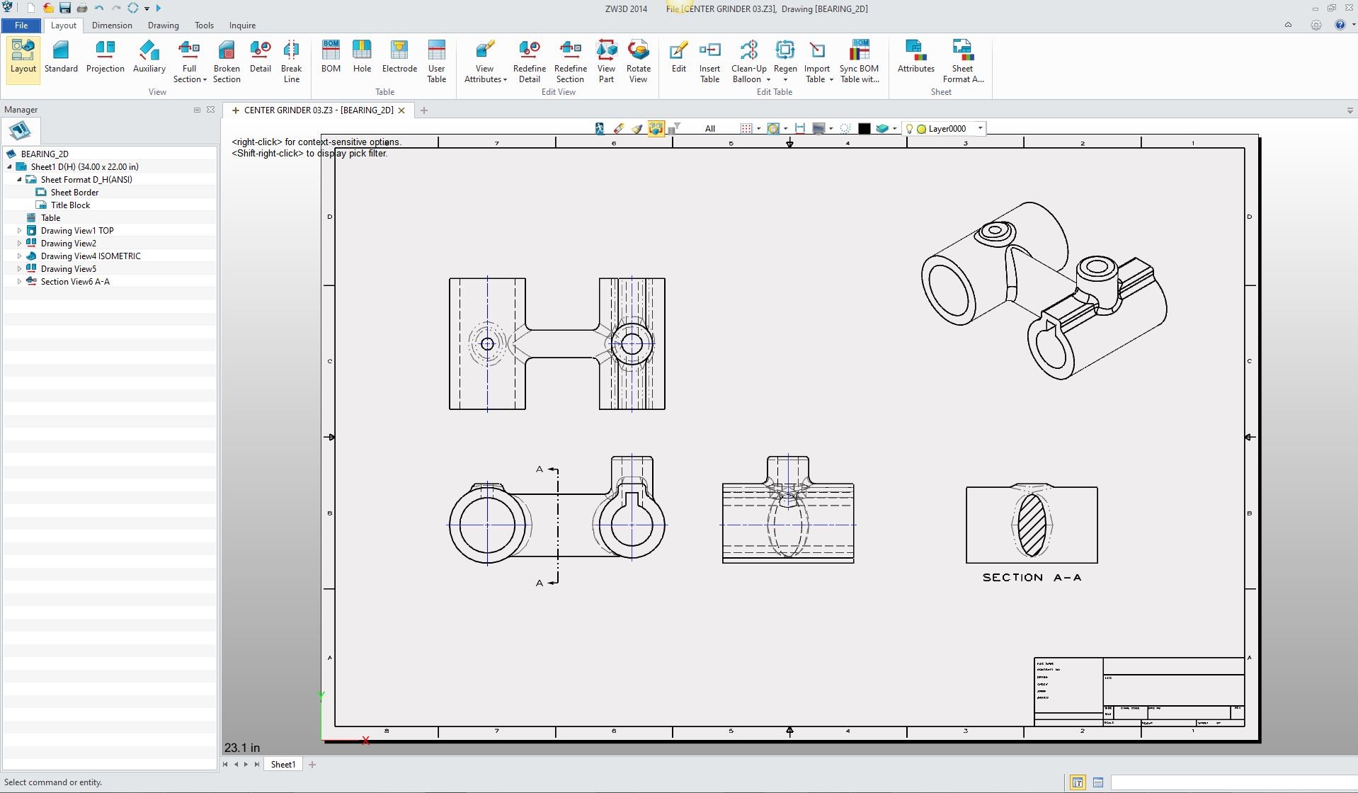 We can also do it with the assembly. Here are a couple of sheets defining the assembly. Notice all the sheets are in the same file defined by tabs on the bottom. 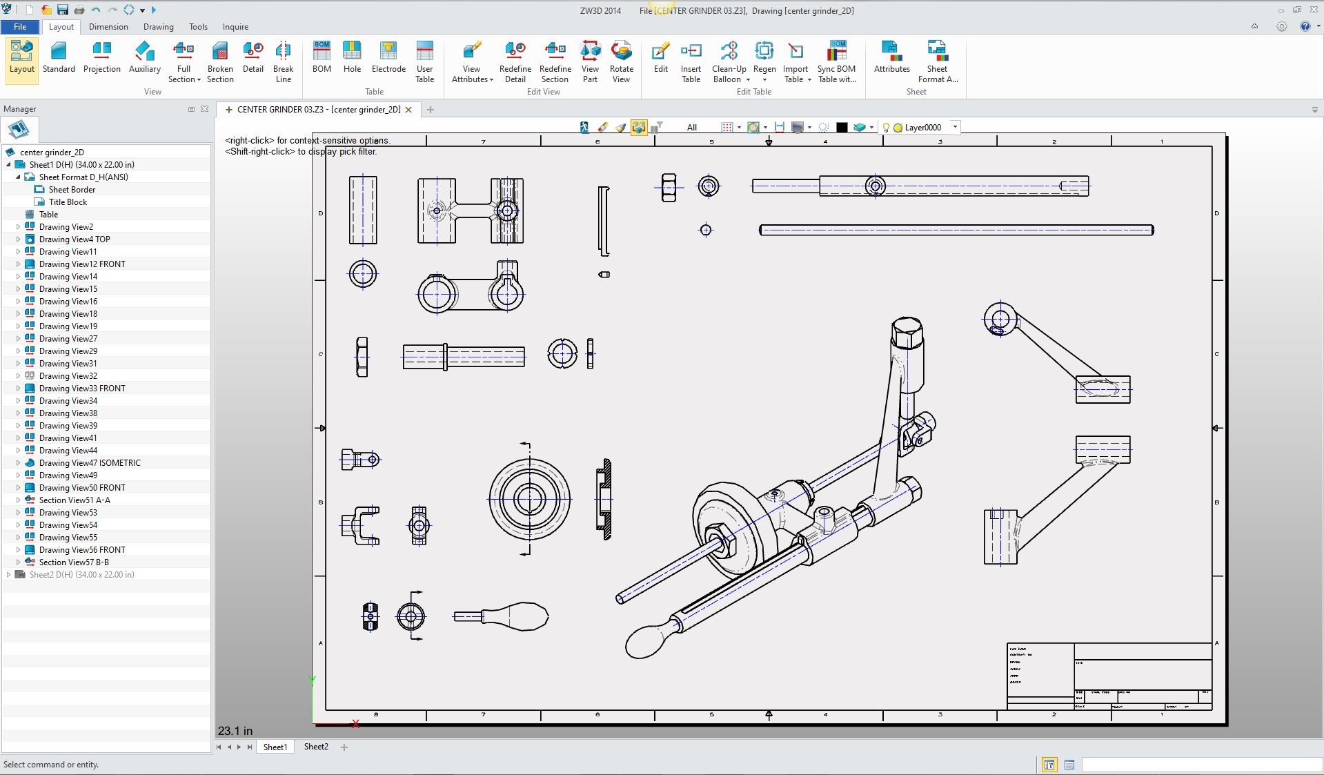 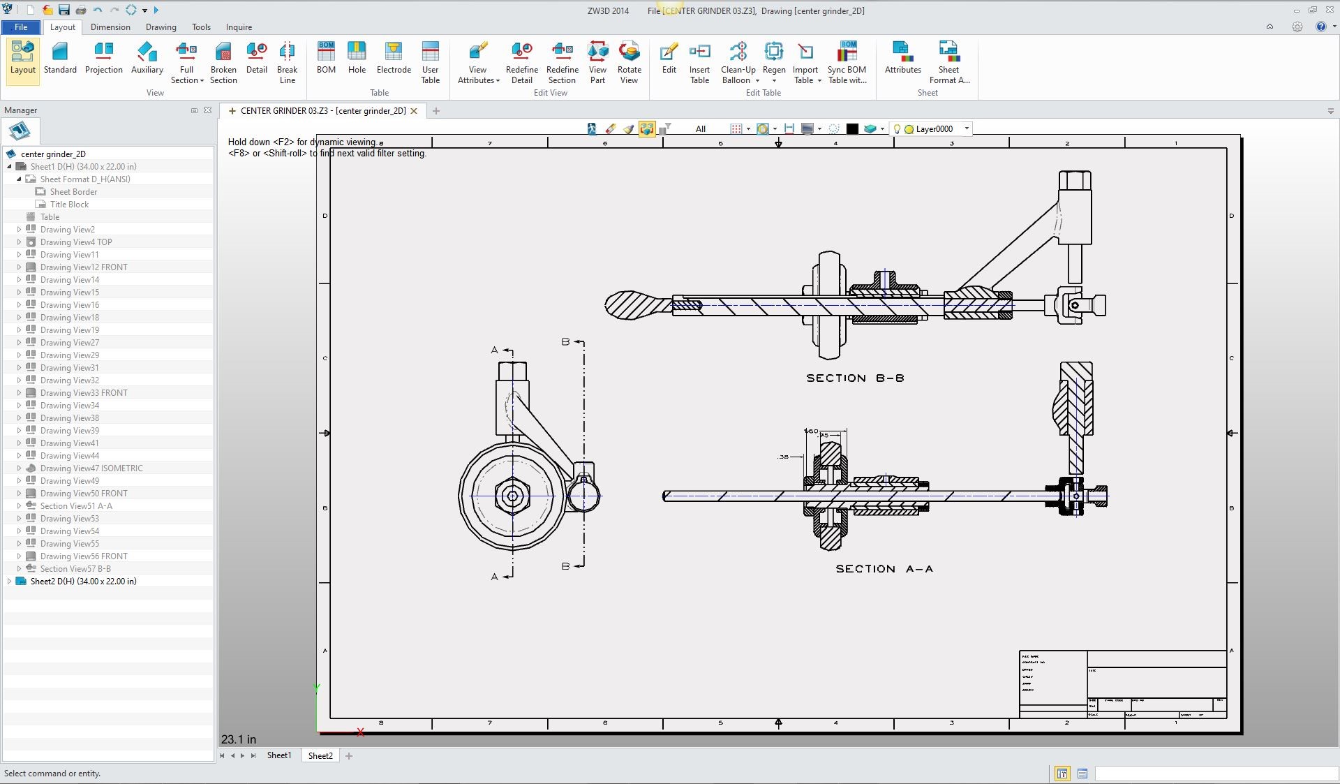
We could have all the parts documented in the same file. Imagine only having
“ONE” file to maintain. Even if you did do associated part in a separate
assembly the drawing would be integrated with the part file. Nothing could be easier. The lack of this feature has caused the industry to
develop the MBE/MBD process with the minimized PMI which is nothing but a
Band-Aid devised by those that have no applicable experience or knowledge of
the requirements of engineering documentation.
They are trying
to use the native file as the engineering deliverable. Which is impossible. So, let’s look at this solution and realize the
incredible cost advantage on so many levels. If your engineering deliverable is the model and a
drawing as a PDF, nothing really changes. Anytime you move to a new 3D CAD
system you need to keep the old system, more than likely forever. I am sure
there are many companies that still have their AutoCAD available. Now if you are large company and your engineering
department is under the control of the PLM gurus and they have implement the
unworkable MBE/MBD based on the PMI. You will have to go through a paradigm
shift of “Back to the Future”. I really do not think that the large companies
have the applicable knowledge to make this happen.
They have to put the engineering department back
in the hands of engineering. The solution we suggest is ZW3D Try this concept today. Download ZW3D and import an assembly as a native or neutral format. It comes into one file. You can then edit the parts with robust history/direct edit modeling. Then just create the drawing with feature rich documentation functionality. For more information or to download ZW3D Master 3D CAD Design in 3 Hours! The cost savings can not be overlooked! It has all the above benefits and superior performance
to the top programs. But ZW3D’s claim to fame is the cost. It offers two levels of design ZW3D Lite ZW3D Standard We
ZW3D comes with translators that can read all the
popular programs. It can read the PMI from Creo, Catia, NX and Solidworks for
those companies that are trapped in the MBE process. ZW3D is an obvious solution to bring the 3D CAD world out of chaos.
The Very Best 3D CAD Rental Offer!
ZW3D also offers an integrated manufacturing solution!
ZW3D - The Case for Inexpensive Integrated CAD/CAM!
|

TECH-NET ASSOCIATES | RENDERING OF THE MONTH | CAD•CAM SERVICES
HARDWARE | TECH TIPS | EMPLOYMENT | CONTACT