|
Five Unique Functions that Increase 3D MCAD Productivity
Many of us are using programs successfully, never really taking a look to see if there is anything new or more productive in the market place. Even though IronCAD was released in 1998, its basis is much different than the Solidworks paradigm with the complexities of constrained sketching and the separate part, assembly and drawing modules. The problem with this concept is that it is not easy to do the extensive changes that may be required in the real world of design, we all know the only constant in engineering is change. Many of the programs have gone so far as to add ineffective direct editing modules to give the appearance of making it easier. Well we have a product that solves much of the bottlenecks created by this paradigm. IronCAD & INOVATE are the "only" products with this combined functionality.
If you would like to see these functions in action take some time to view our webinars.
This is a great article explaining each step in a very informative IronCAD presention
IRONCAD Tutorial Video Deconstructed!
If you would like to experience them your self, please download IronCAD!
For More Information or to download IronCAD
Function Number One:
Single Model Environment - No PDM until the design is done
Flexible CAD Assembly and Part File Management
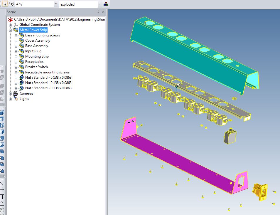
IronCAD is the only history based product that offers this capability. Imagine starting your design by building one part at a time. You can then create the mating parts by projecting the necessary features. Your sub-assemblies and assemblies can coexist in one space. Only when the design is done do you have to create the separate parts and files if at all. If they unique parts to this assembly you can actually detail the different parts and assemblies in an associative drawing module in a single file. If you have only used the Pro/E paradigm this is a new experience that gives you incredible flexibility and freedom.
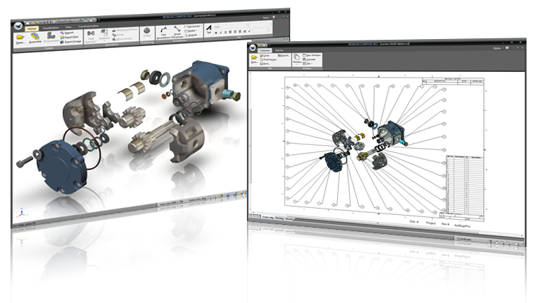
Below you can see the scene browser or tree. The parts are all within one file. Now that the design is done I can externalize these parts or just define them in this assembly. This is a special exploded view configuration that allows moving the parts without affecting the original locations.
Function Number Two:
Drag & Drop Design from Standard and Custom Catalogs Common parts at your fingertips
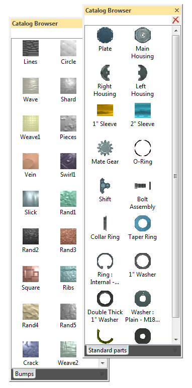
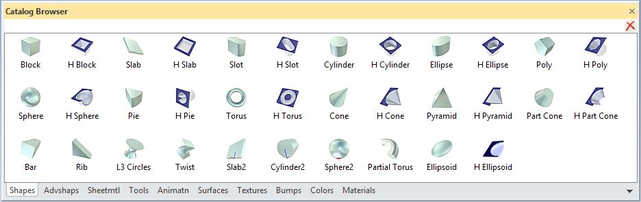
There are a few programs out that that allow you to insert primitive shapes. IronCAD capability is much more sophisticated. You can drag & drop multitude of standard shapes from the standard catalogs or create custom common features, parts or assemblies. These are positive and negative features and shapes. You can create custom catalogs of special features, parts and assemblies. All of the shapes have handles to quickly adjust the size or to match other shapes or parts and are based on editable sketches. IronCAD Intellishape Deconstructed What are we Dragging and Dropping?
The catalogs offer more than just features, shapes, parts and assemblies.
This increases you productivity incredibly. You truly have to experience drag and drop design if you are stuck in the constrained sketch only world of the Pro/e paradigm with program such as Solidworks, Inventor and Catia 5. But there is one more fact, you can still design in that world when there is a need. The features and shapes are driven by an embedded sketch.
When you desigin in IronCAD your first choice is drag and drop, second sketching, then integrated direct edit and finally surfacing.
In this article I introduce many examples Streamline Sketching and Feature Based Modeling that can be utilized in any CAD system increasing productivity 5 top 10X. I compare Fusion 360, Solidworks and Creo in these lessons.
3D Modeling Techniques Defined
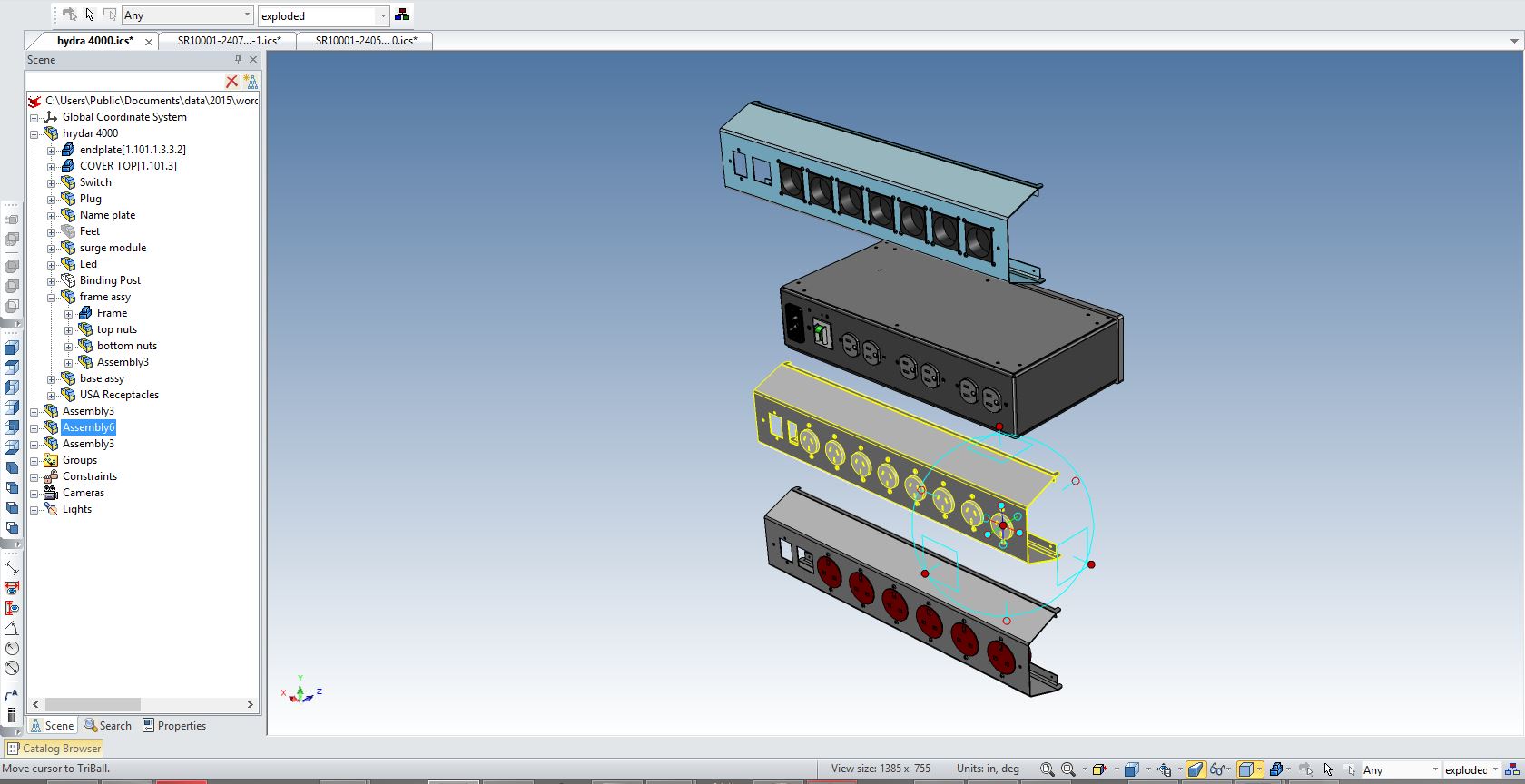
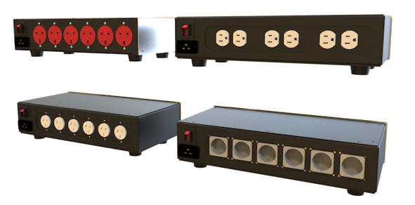
Function Number 3 Most of us are in an industry that designs similar parts. Now IronCAD offers the custom catalog for the most common features, parts and assemblies. But many times you many need a part or an assembly from another project, native or imported, to serve as a basis for a new product. IronCAD being basically a Single Model Environment, lets you design complete projects in one file, so you can bring it up and all of the parts and assemblies are available to you for your current project. Also, as in the catalogs, the history is still intact. As you can see in this image below. I am designing an enclosure that is going to have common faceplates for the different receptacles. This is completely described in this article "Reusing 3D CAD Models for a New Product" Notice that I have copied and pasted the components I will be using from other projects. I only copied the parts and assemblies that I will need for the job. The dark gray part is a similar product with which we are going to start. This is an exploded view for clarity that does not alter the original location of the components. This process starts with Change! No need to fear change with IronCAD! Is 3D CAD Productivity an Oxymoron?
Function Number Four: Integrated Direct Feature Editing - Legacy data is no problem
Are You Stuck in a 3D CAD Wagon World?
Enter direct feature editing: Pro/E was the first to look for a solution to the limitations of the history based design of fast changes and the capability of editing what is called a dumb or non-native solid. They purchase one of the first direct editing products on the market, CoCreate. Soon Autodesk and Siemens followed with Fusion and Synchronous Technology.
Solidworks added limited direct edit in 2010. Creo, NX, Inventor and Solidworks can not utilize direct editing in the design process due to creating a step in the history with every face move.
Siemens with NX and Solid Edge have attempted to integrate the direct editing but it has problems, it really is not functional.
Solid Edge vs. IronCAD, Direct Editing
All have accepted both history and direct edit as a complete solid modeling solution There is only one package that has not yet embraced both concepts, Catia 5 from Dassault. I have heard there is some direct edit functionality in Catia 6.
Does anyone wonder why Catia 6 has not been readily accepted or implemented? It has been out for years. I have never seen another product with this problem. Most folks are excited about moving to the latest version of the software. I wonder if Catia 5 has any new enhancements since the release of Catia 6.
Learning IronCAD! Lesson 5 Integrated History Based/Direct Edit Modeling
IronCAD has Both History and Direct Edit Fully Functional Integrated in the Program.
Many of you cannot imagine not being able to design with a history based system, well neither can I. IronCAD having both integrated into a system gives you the most flexible design tool available. It truly is a pleasure not to have to worry about design intent.
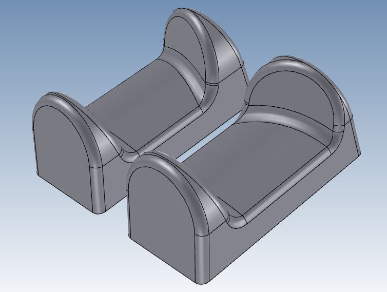
Here is an example of IronCAD and its integrated direct editing capability:
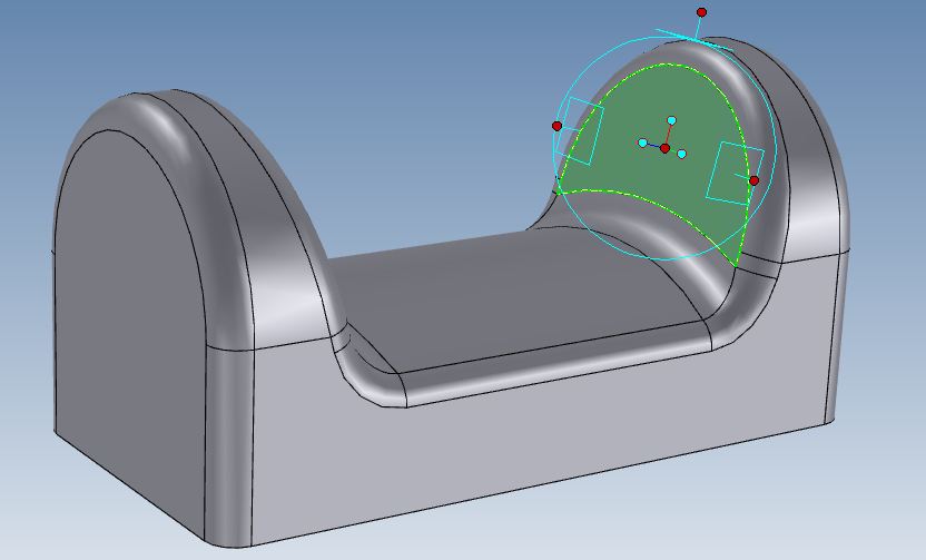
Here is a shelled shape. We select the face and with a right mouse click with select move. The Tri-ball comes up to manipulate the surface. We are going to rotate the selected face.
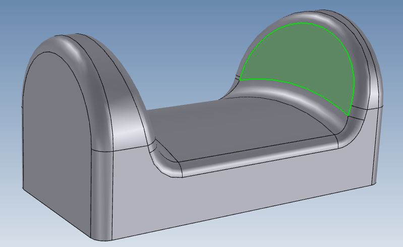
We rotated the surface 15 degrees.
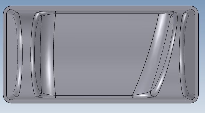
We had a shell function in the history this shows that the shell did get updated.
Imagine working without worrying about the design intent. You have the freedom of incredible conceptual history design with the ability directly edit the part when the design requires it.
Function Number Five
The Incredible Tri-Ball - Often Copied but Never Duplicated
(Virtually all direct editing package have a Tri-Ball Clone, including SWMC)
Many of you have seen feature, part and assembly manipulation tools show up in your programs. I am sure you thought they were very clever and productive, but a bit cryptic. Ever wonder where they got the idea? The Tri-Ball has been with Ironcad since the Trispective days in the early 1990's. It is not just a feature, part and assembly manipulator. It does so much more. It locates, copies, mirrors, links, it is used to manipulate surfaces, mating parts, etc. You have seen the Tri-Ball used above in direct face editing.
Here is a great write up describing the Tri-Ball
The Anatomy of IronCAD's TriBall
The Tri-ball with a hit of the space key allows the Tri-ball to be moved to a location where you may want to create a pattern.
Here is how it works:
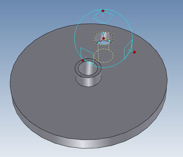
I have created a flange and now to create a bolt circle.
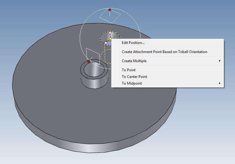
We push the space key and that turns the Tri-ball white which means we can move it to the location where we want to rotate the hole.
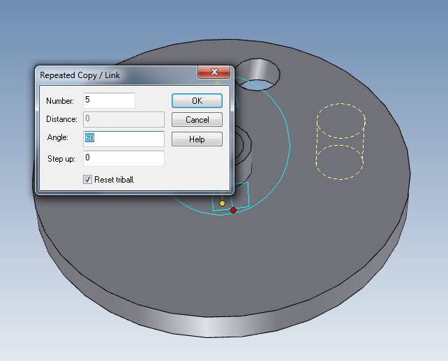
Now that we have the Tri-ball in the correct location we can now perform the operation. Notice you can select to reset the Tri-ball to the original position after the procedure.
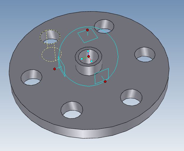
Below shows the holes installed. We could have also created a editable pattern.
As you can see the Tri-ball power even in this simple example.
Conclusion
These five functions are only combined in IronCAD and are guaranteed to increase your design productivity. They provide a completely different paradigm even though being around for years. Give yourself a treat and download an evaluation copy of IronCAD. It includes all of the popular translators so you can directly read your existing CAD parts and assemblies. In fact it is easier, in many cases to modify your parts and assemblies with IronCAD than with the original package. We are the only CAD package with an inexpensive modeling only package for those that just want to add these easy to use capabilities to their existing CAD system.
See all of these function presented in the following Videos.
Lately I have done some 3D CAD product comparison exercises and they soon turned into a study on modeling techniques. Take a look at few of these exercises and realize the wasted modeling hours using only the sketch, sketch, constrain, constrain modeling process that most are trained and are the basis for all the Solidworks clones.
3D Modeling Techniques Defined
To experience this increased level of productivity, please download IronCAD for a 30 day evaluation. Legacy data is no problem, IronCAD can read the native files of all of the popular programs. IronCAD is a great replacement for the subscription only Autodesk and PTC products. IronCAD Now Available for Rent! IronCAD now offers a annual rental program at $1,500.00 A great way to get into the incredible increased productivity of IronCAD. For More Information or to download IronCAD IronCAD is much different than the popular Solidworks clones. The above features offer a complete different, more flexible and productive design process. Please use this excellent training tool to get introduced to this unique 3D CAD design solution. Self-Paced Training Guide - Introduction Please visit our newsletter series:
IronCAD offers much more than the basic Solidworks clones! Leverage Your Engineering Data throughout your Organization! Leverage Your Engineering Data - Sales, Publication and Marketing Leverage Your Engineering Data - Manufacturing Checking, Design Review, Manufacturing and Data Extraction Simplifying Your Design Process
TECH-NET Engineering Services!
|
 In my experience there is no more productive environment that allows you to freely design in a space where you to do your complete design without having to worry about naming and saving your parts or assemblies until the design is complete.