|
Learning IronCAD! Lesson 5 Integrated History Based/Direct Edit Modeling Using both Paradigms in your Design Process!  |
|
Note: IronCAD is
such a innovative 3D CAD system that I have to give a brief description
of the basic 3D modeling philosophy and a bit of history as compared to
the major history only CAD systems based on strict constrained
sketching, what I fondly call the Solidworks Clones. If you are already
an IronCAD user or are aware of these differences please continue to the
training segment of the article.
If you would like to join in: Down load IronCAD here This is a 30 day fully functional IronCAD evaluation including the Translators for all of the popular programs. Go ahead and import parts and/or assemblies. You can actually modify the parts faster than in the original system. I will be posting new lesson relatively often. If you are interested send me your email and I will make sure you get the new lessons. Please start with the lesson 1. Learning IronCAD! Lesson 1 Setting up the Scene (Workspace) If you get ahead, here is a great getting started Tutorial. Self-Paced Training Guide - Introduction Direct Editing showed up on the scene with the FastSolid add-on for CADKEY in 1995. It was, what we called a Boolean system, we would add and subtract shapes. It was a bit clunky in the beginning, but today it by far surpasses the productivity of constrained sketch based history design in simplicity and ease of use. I was told that Catia 4 was also Boolean. So my first solid modeling experience was with Boolean which became direct edit modeling. I was introduced to Trispectives, an ACIS base graphics design system that you would drag and drop shapes from a catalog. Trispectives was purchase by and OEM for CoCreate (Now Creo Direct) and they integrated history (made up of drag and drop Intellishapes and sketching) with robust direct editing. I quickly move my design to IronCAD as my preferred design tool. IronCAD is an Integrated History Based/Direct Edit Modeling system designed from the ground up. You use both paradigm in your design. The only other program that is even attempting this is Solid Edge. It has done an okay job trying to integrate its ST (Synchronous Technology) into the history based system but it has some huge flaws, which I will show you below. Here is a case showing a common direct edit situation. Here is how IronCAD handles it. We are going to rotate the right face in two directions in two separate steps. We use the Triball to make this move. 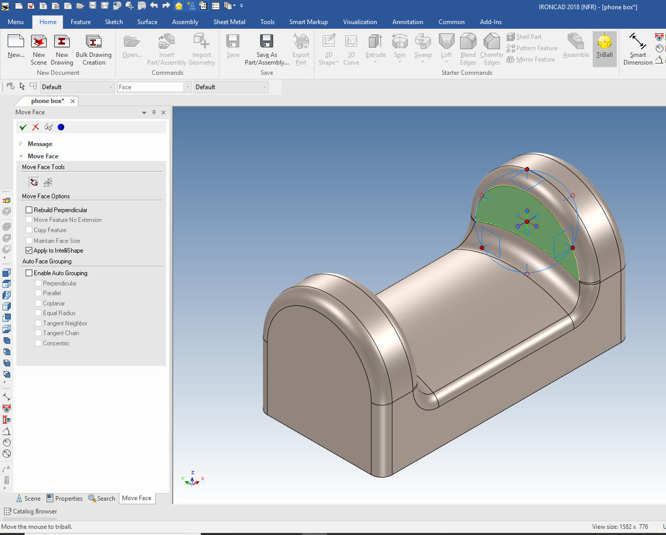 We get can get this warning, but many other times it will not cause a problem with the intellishapes.  After the move you can see that the history has consumed the H Block that made up the center cut and we now have a Negative Brep that has replaced the cut. You can see how simple and straight forward the construction of parts are. Direct Editing is designed to be used in the design process. 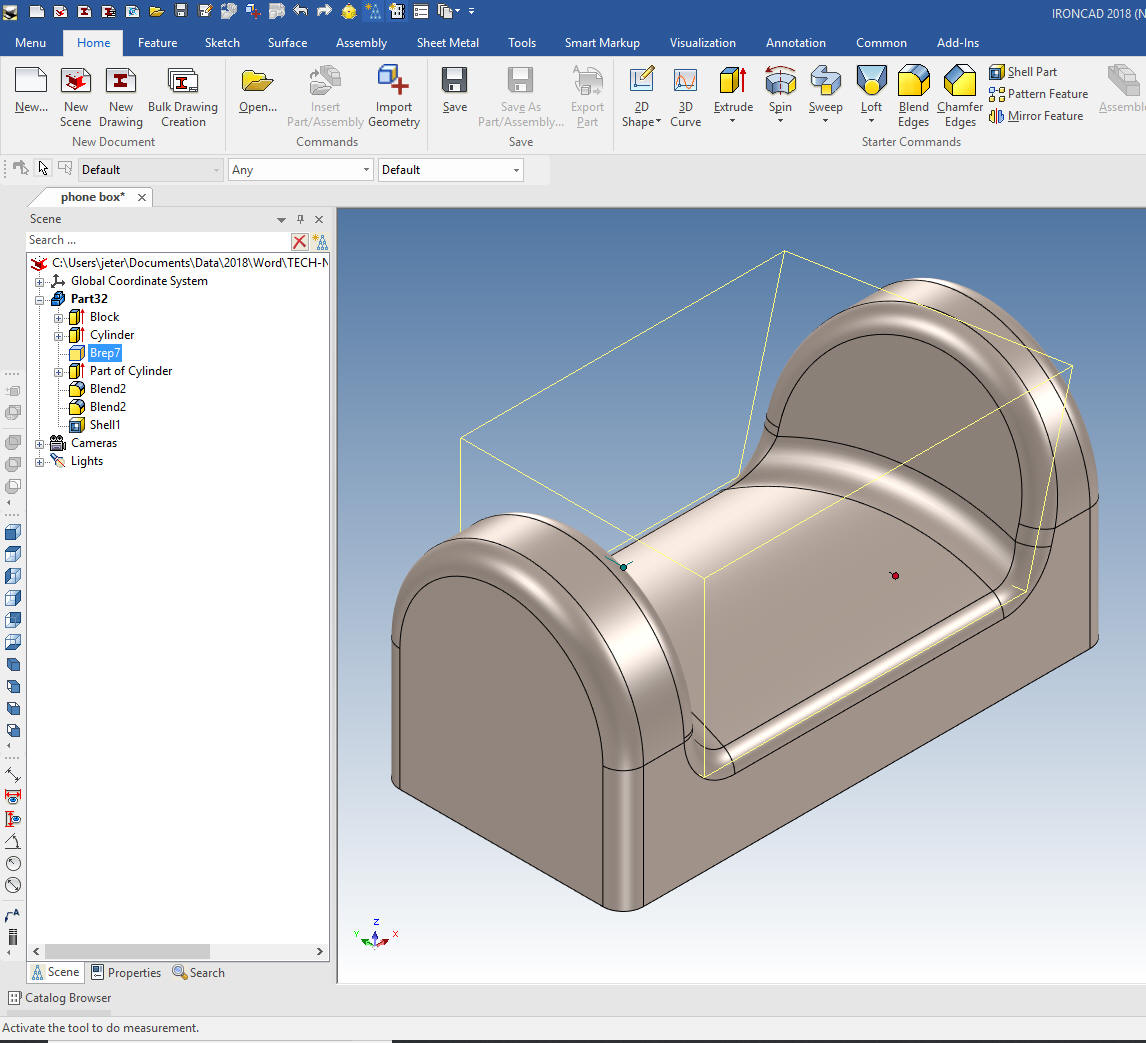 Solid Edge and probably NX are the only other system that offers integrated history/direct edit, below is an example of the same part in Solid Edge. You can see it does not show the direct edit move which is a requirement for an effective integrated history based/direct edit system. Having a face move as a step in the history is virtually unworkable except in the simplest of operations. With Solid Edge you still get some unexpected results if you try and edit the history. You can see it is much more complicated than IronCAD. It was also more complicated to make. The Triball like manipulator was a bit unintuitive, but I got the part done. I feel that direct editing is only marginally effective in the design process and most designers would probably avoid using it. Solid Edge is not a single model environment so each part is a separate reference file. 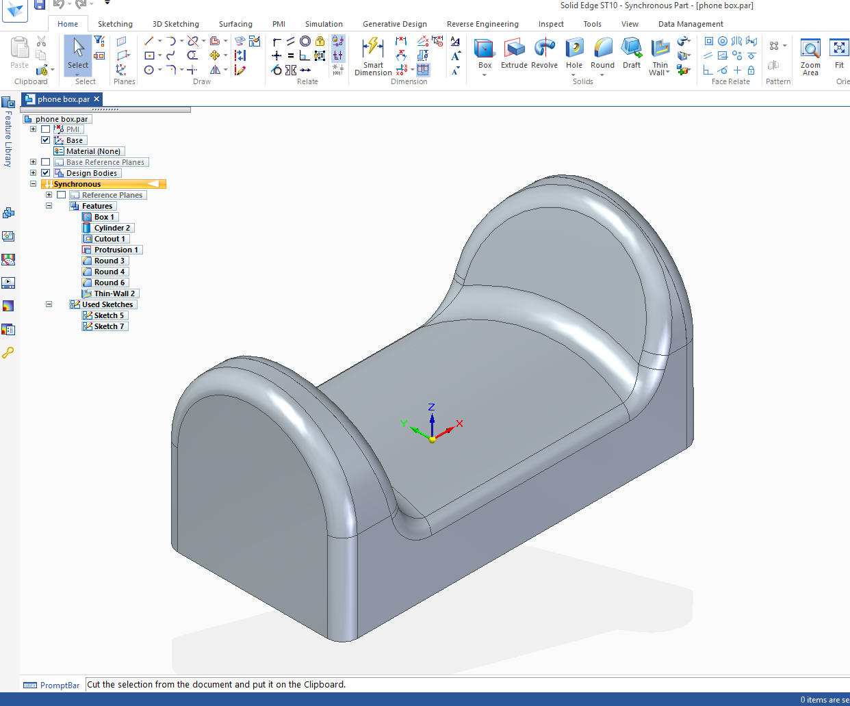 Here is a comparison of IronCAD vs Solid Edge direct editing. All other CAD systems add a step in the history for each face move. If you add many face moves it can get quite confusing and unmanageable. Here is a comment from an expert Solidworks user that has attempted to use direct editing as part of the design process. "Yes, direct editing in SW can be used in the design process. However, it should be done with extreme caution. Sometimes, direct editing is just the obvious way to go. However, used incorrectly (and it's far easier to use incorrectly than the 'normal' tools), it makes the part a royal mess. I'm currently dealing with a few parts that were made using extensive direct editing. It's nearly impossible to track down what parts of the history you need to change to maintain everything else, and make even a simple change." So there you go. The state of the attempted implementation of direct editing into the major CAD systems. Only IronCAD offers a effective mixture of history/direct editing flexibility in design. History/Direct Editing used in an actual project Here is a job I have been working on. I will show you the iterations of the progress of the design. We first develop a concept. Then as the design develops new requirements and concepts get introduced. I will show you 5 different iterations and how easy they are to model. Since this is a new product we will work only with the cover of the plastic enclosure. Notice the history in the scene browser. All of the features are there to modify. It is now no different than a model done in any history base product. 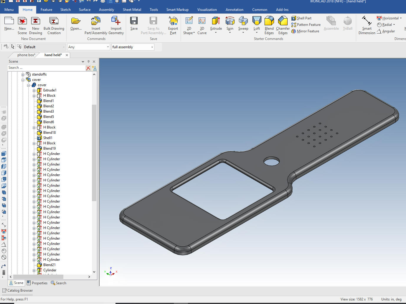 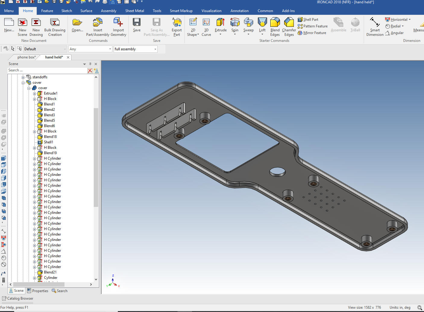 Version 2 We copy and past Version 1. This is just modifying the existing history. I did the minimum to show the new concept. 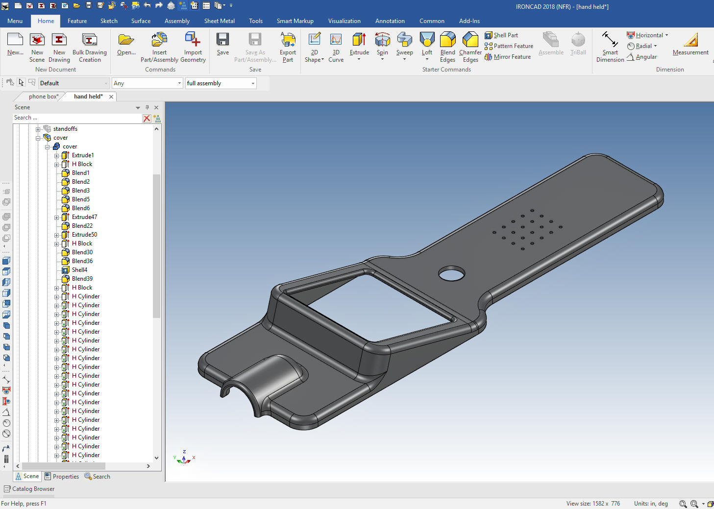 We now copy and past Version 2. Version 3 - Again I do the minimum to define the concept for the customer. 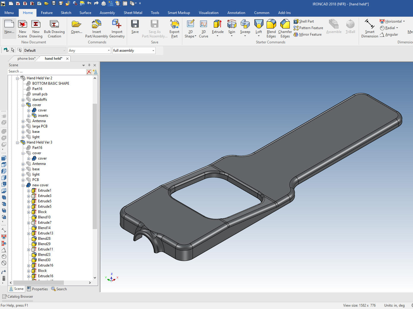 Version 4 - We added an insert in the back the logo has been removed. The holes were all selected an moved with the Triball. We just modified the basic shapes to get to this version. They are based on the previous versions. Mostly pushing an pulling basic shapes and editing features. 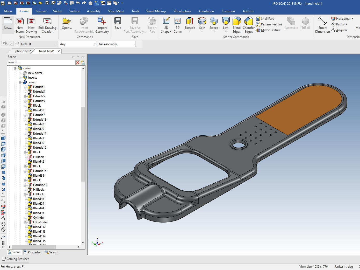 Version 5 - The concept changed considerably. As you can see I did a complete redesign. I used cross sections from the Version 5 to complete this concept to completely rebuilding the part in less than and hour including the bottom cover. 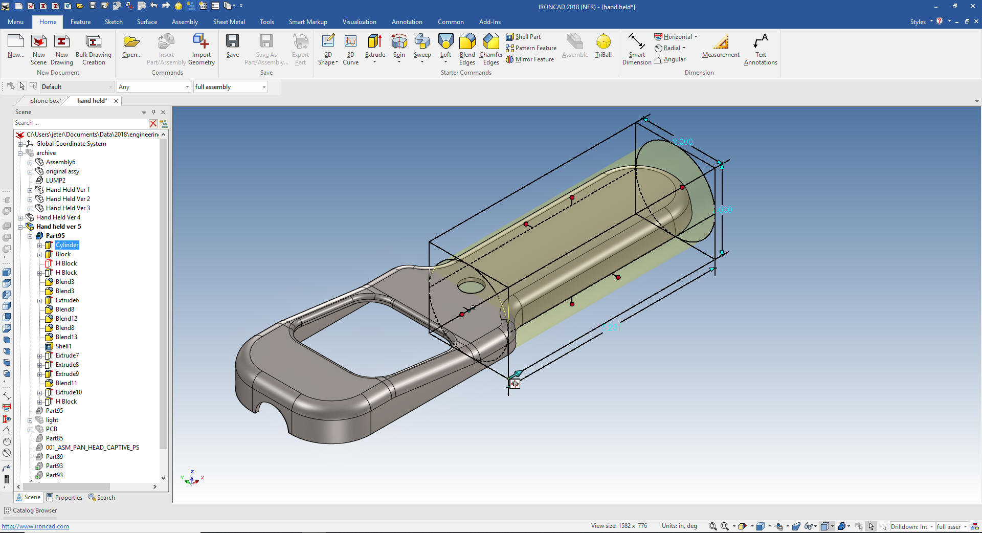 The first 4 versions were copying and pasting the earlier versions and modifying them. You can see all of the versions in the same file. Imagine doing all of these different design concepts in a Solidworks clone. Look in the scene browser and see that I have creates an assembly of the first 3 versions and named it archive. As many of you know we may go back to an earlier version. This all was done in one file. 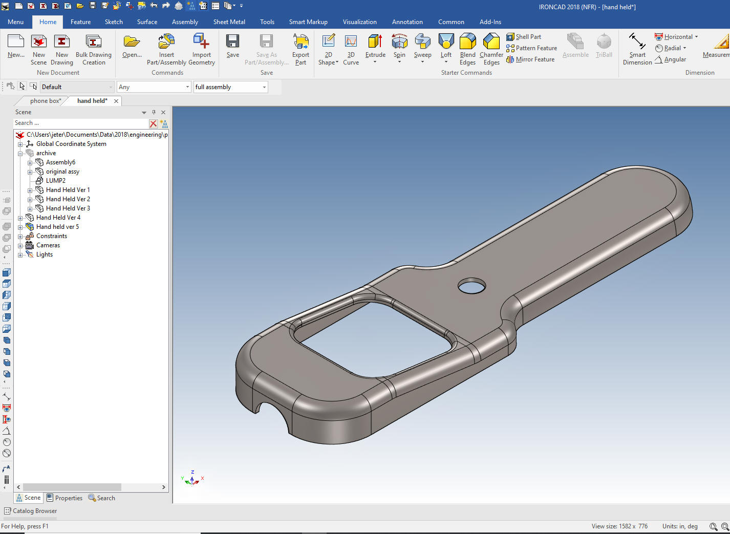 Even though IronCAD is a single model environment it has a separate documentation module. Here is a single AID that shows all of the iterations of the design. They are defined by configurations that have other parts and assemblies suppressed. I have 5 more AIDs that define different concepts and problems. Realize you have a complete project, parts and sub-assemblies and documentation in two files. Yes, you can have referenced parts and sub-assemblies for larger projects. 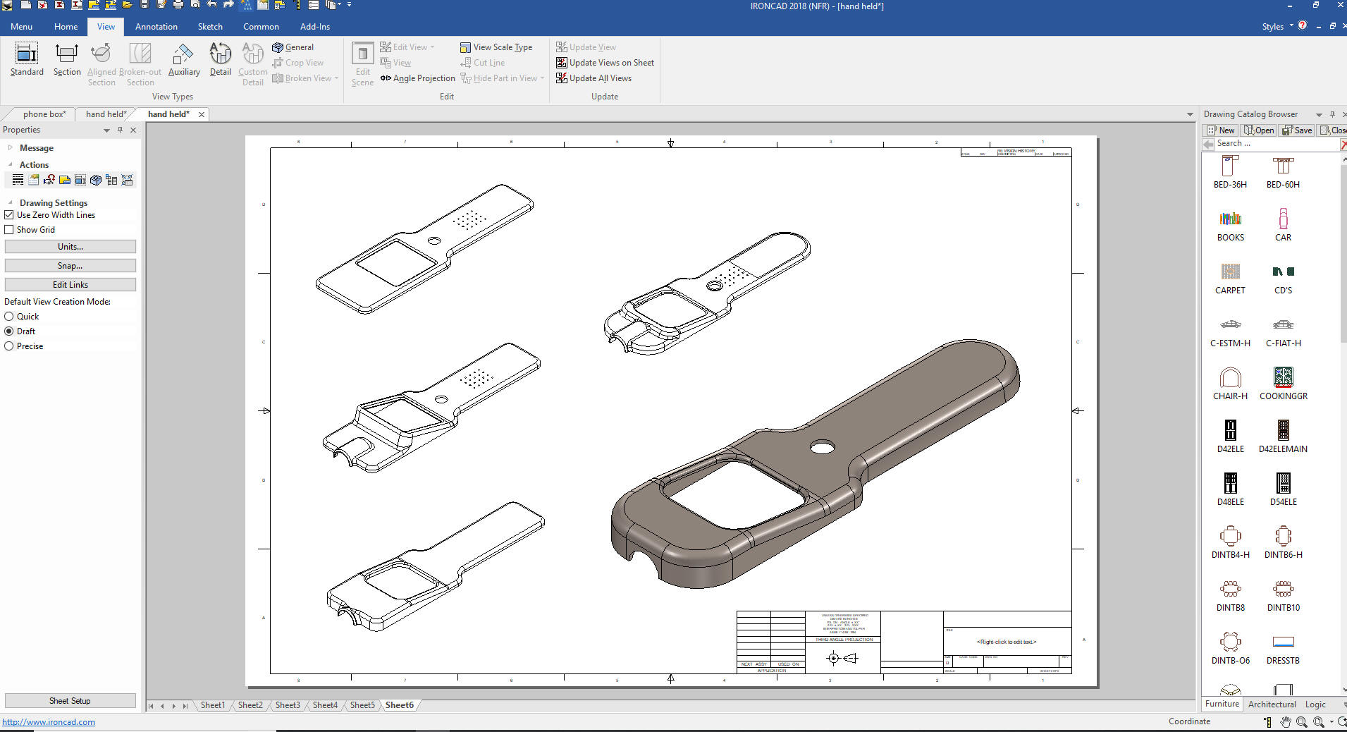 IronCAD Lesson 5 Direct edit in the design process. Let's go back to the first example. I want to show history and direct edit both used in the design process. I will also show a few clever tricks. We will drag and drop a block and size it to 6x3x1.5. 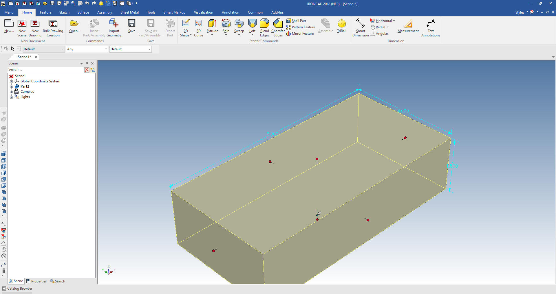 Now we will drag and drop a cylinder. I will rotate the view so we are looking more directly at the end view. This will drop the cylinder correctly even though I am picking the mid-point of the left upper edge. IronCAD recognizes corners, center of circles and mid-points of faces and edges! I drag the cylinder with the left mouse button, if I dragged it with the right mouse button it would give me the option for a new part. 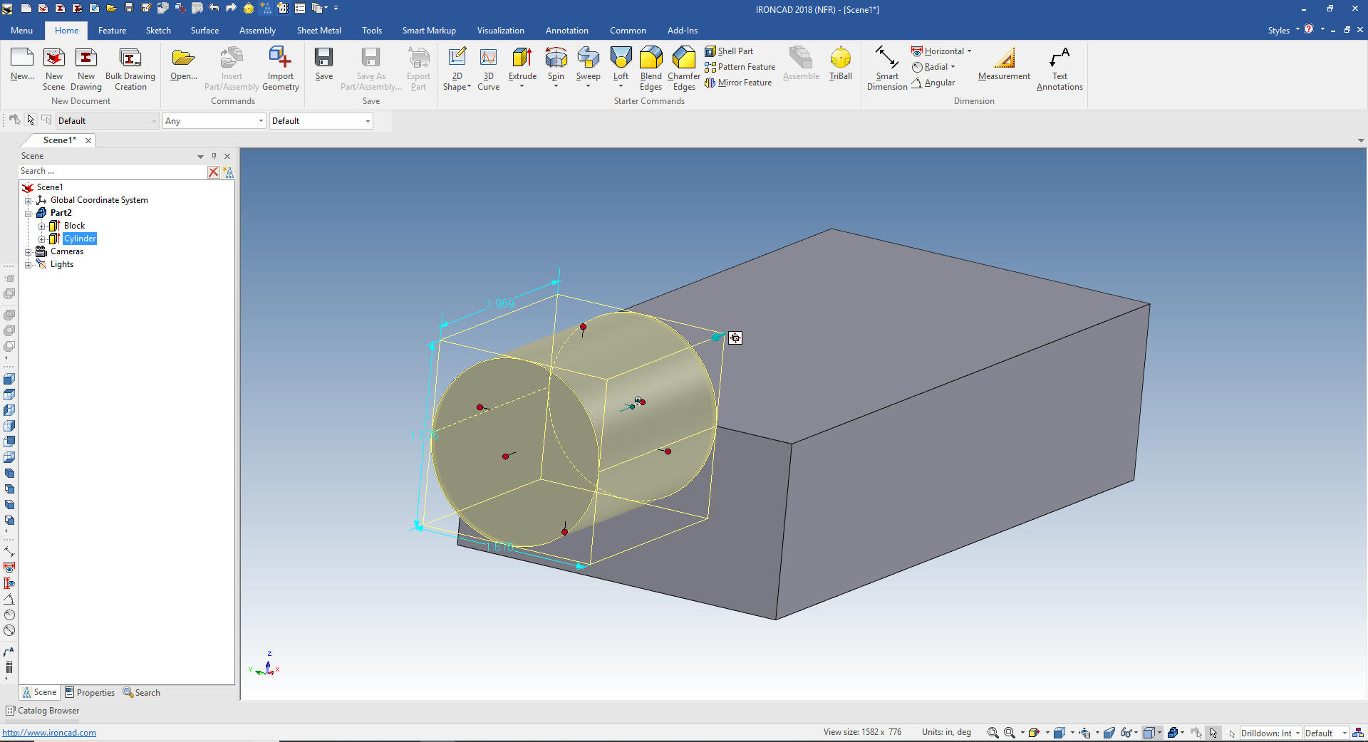 We now size the cylinder using the shift key to snap to the face or point. We will select the upper front edge of the part. Rarely do you put in explicit numbers. You use existing geometry to design your parts, so much more productive than constrained sketching. 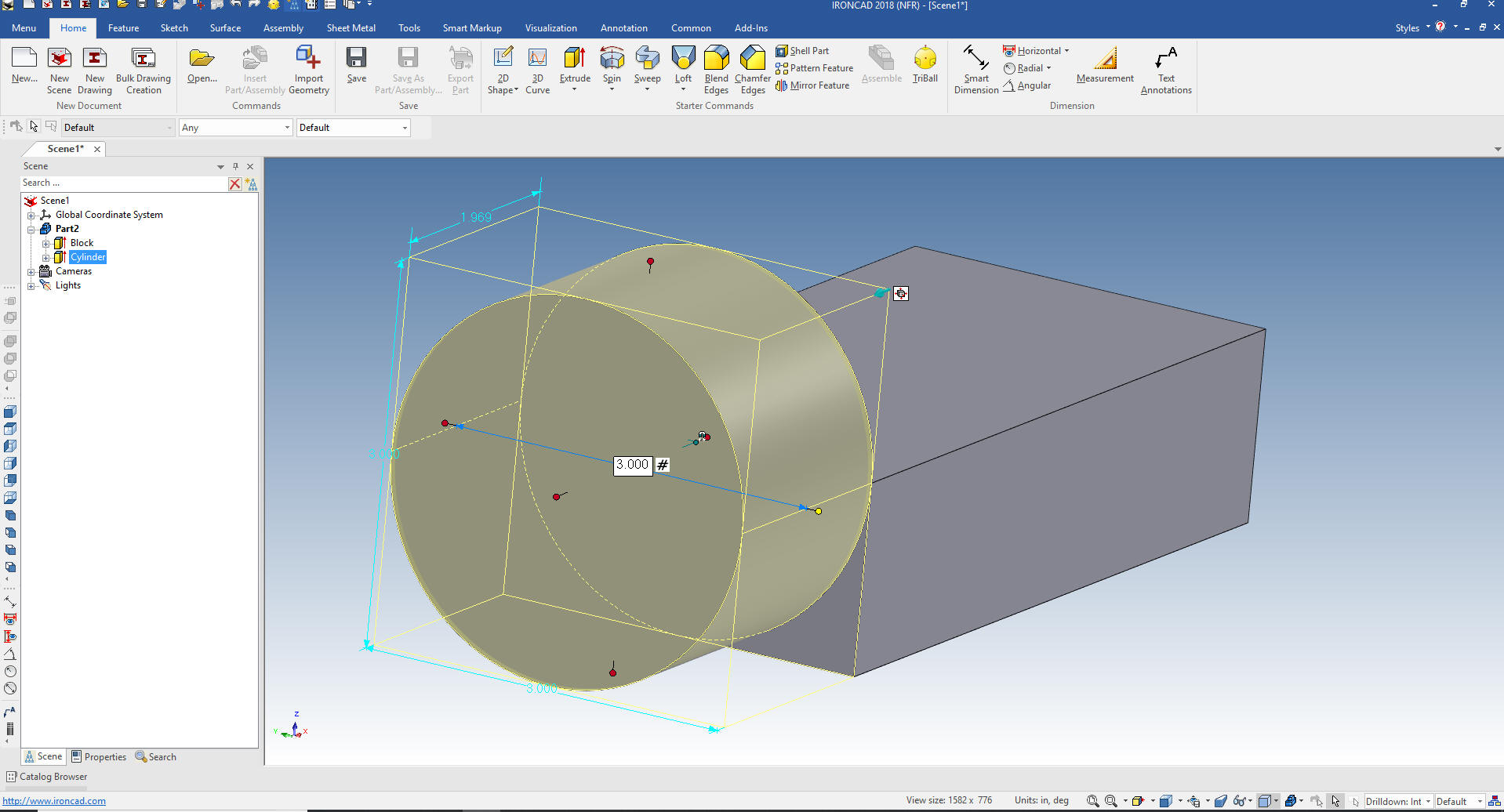 Now we pull the cylinder and snap to the ends, using the shift key. 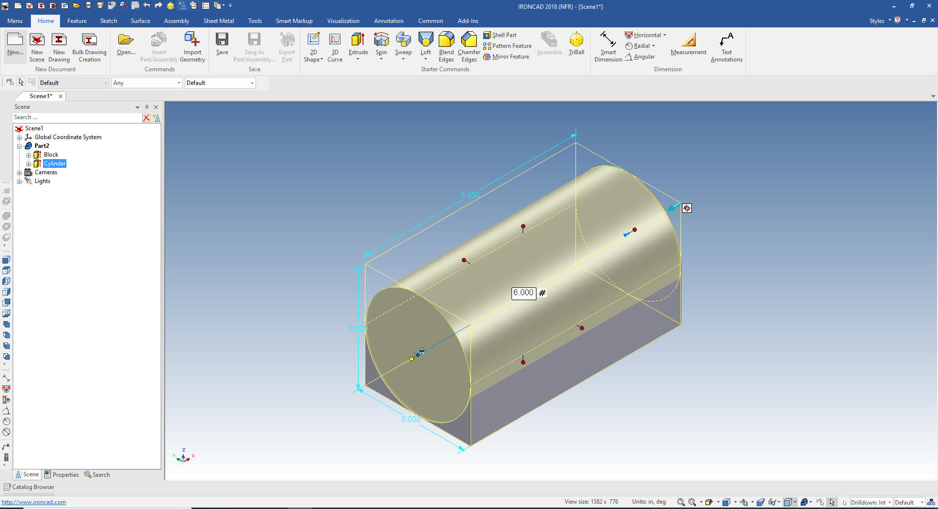 Now we will drop a hole block on the mid-point of the front face and size it. We snap the bottom of the hole block to the bottom of the part select that handle and subtract 1.00 from the number. Pull the left handle snap it to the left outer face and then subtract1.00 from the number, then select the right handle and put in 4.00. 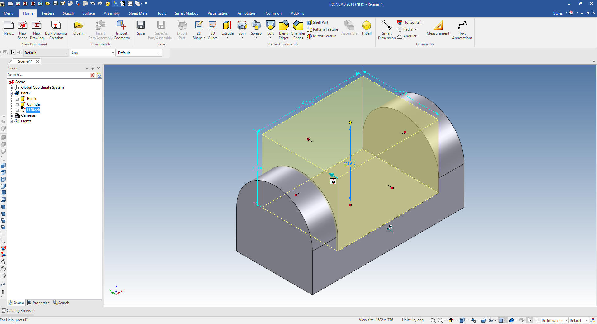 I will now show you how to manipulate an Intellishape. We will drag a "part of a cylinder" from the advanced shape catalog on to the mid-point of the new face we created. It comes in cattywampas. I have also pinned the catalog to be shown. 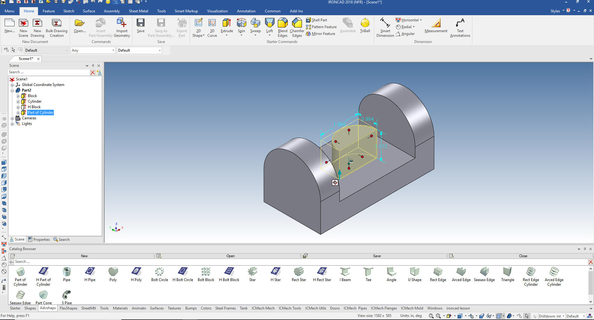 Intellishapes have anchors. We can change them. We select "move anchor" from the tools menu and put it on the mid-point of the bottom of the "part of a cylinder" and drag it to a new catalog. 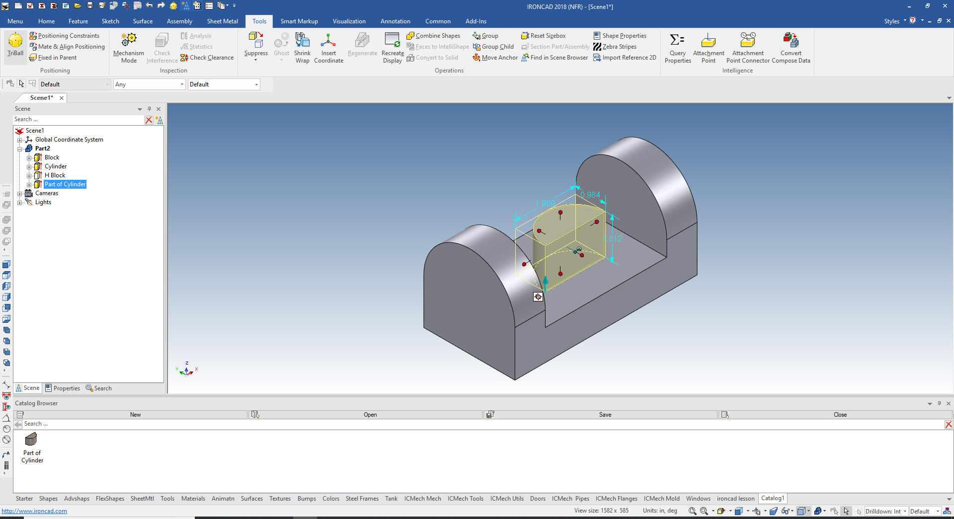 Now I delete the original "part of a cylinder" and drag the new feature from the new catalog, again to the mid-point of the same face. It comes in flat on the face but the feature needs to be rotated.  I will unpin the catalog to have more work space and rotate the feature with the Triball. I could have rotated the anchor but it is a bit easier to just rotate it with the Triball in this case. 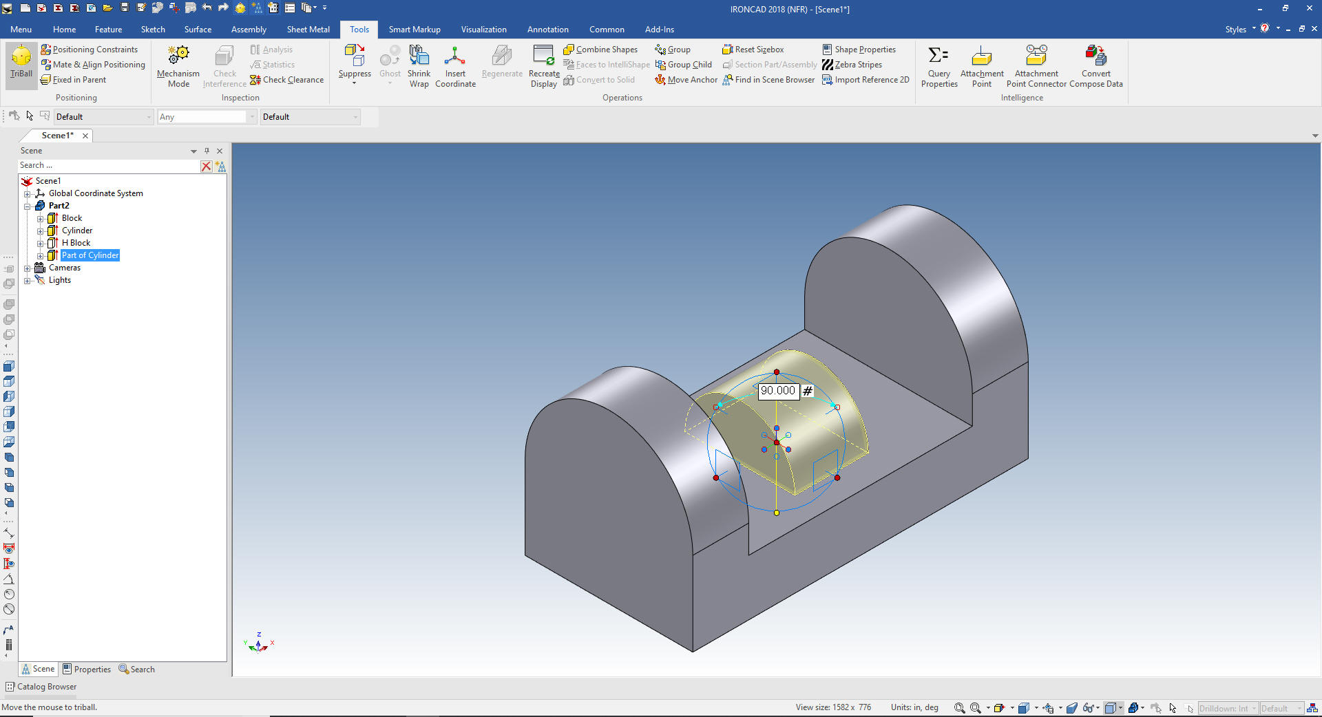 I will pull both edges and snap them to the sides of the part and set the height to .400 and pull the end and snap to the inside faces. Remember we just use the shift key to select the faces or edges to snap to. 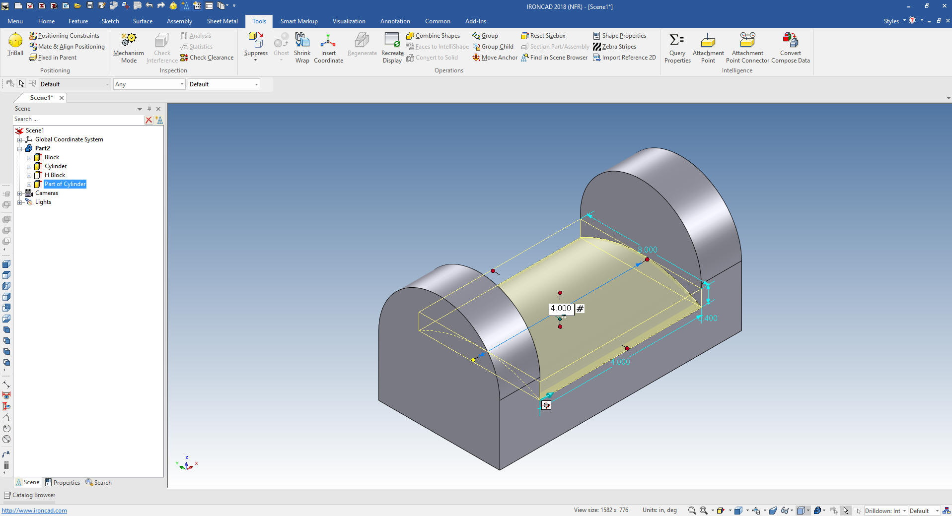 We need to add some blends. The first two blends are .375 the other is .250  We shell the part selecting the bottom face to be open. 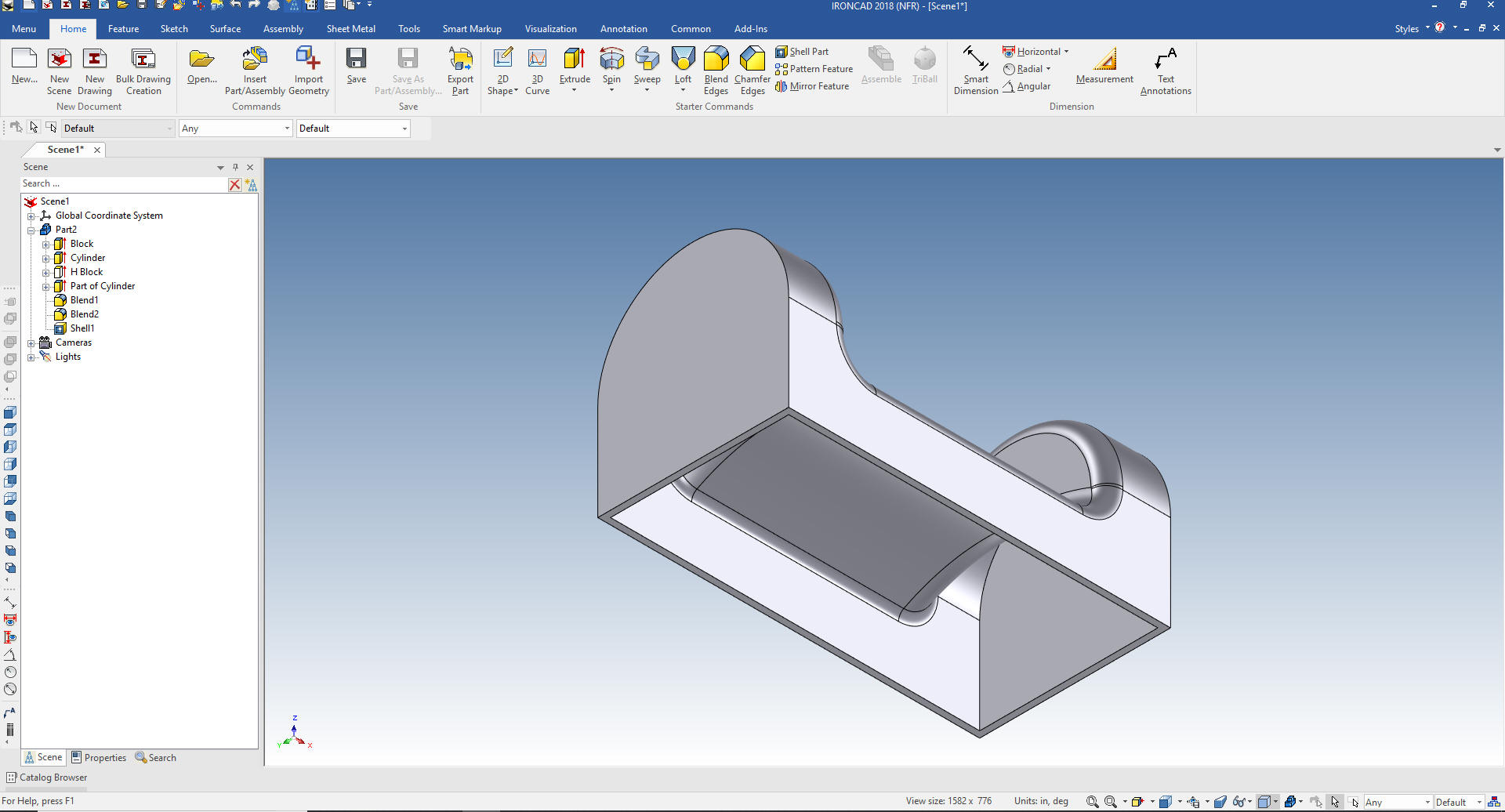 IronCAD can select different levels of the assembly, part, feature and face by clicking the feature with the left mouse button. First click assembly (yellow), second click part (blue), third click feature (yellow) and the final click face (green) as we show here. Now, using the Triball, we rotate the right face 15 degrees around the vertical axis.  Now we again select the same face and rotate it 10 degrees around the selected axis. Notice the Tribal is now normal to the new face. The Triball is the most powerful feature in any CAD system just behind the single model environment. I will have a lesson on it in the future. Five Functions that Increase 3D CAD Productivity!! 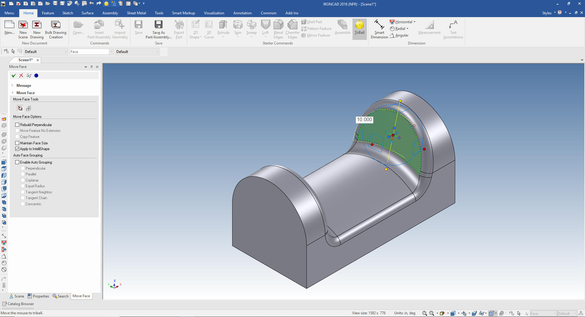 We get the warning that this move will consume a feature in this case will be a hole block. You now have a negative brep. It didn't create a brep for the previous move since it basically just altered the same hole block.  We can move rotate other faces. We are now working with a brep, yes the blends and shell is still available for editing. Very, Very clever. We will continue working on the part with a mixture of direct edit and history based design. You can modify your history only based imported parts faster than the original system. It truly moves 3D CAD to a new level of design flexibility and freedom. Yes, this was released in 1998! I call IronCAD back to the future 3D CAD! LOL 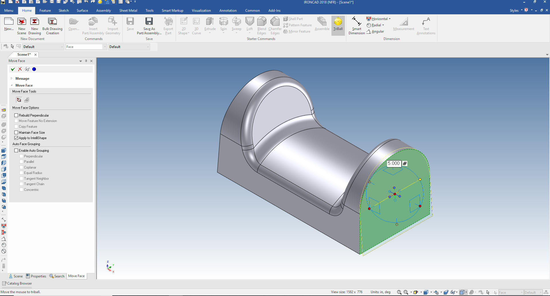 Oops!! I want the Blends to be on the back edges. We just select the original .250 blends and add the edges. 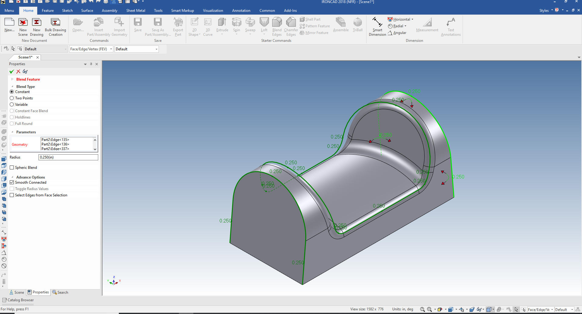 If I would have put new blends in we would have had to suppress the shell and move the blend before the shell. IronCAD is an integrate history/direct edit program. History is by far the best conceptual design paradigm. But the history based only systems have huge problem with modifications even beyond direct edit functionality. Is 3D CAD Productivity an Oxymoron? We are now done with our part. You can see the incredible flexibility that having integrated direct editing can increase your design productivity, 5x conceptual design and 10x with modifications. No you don't cringe at making changes. You can see the shell has been updated for every face move and added blend and still available for editing. 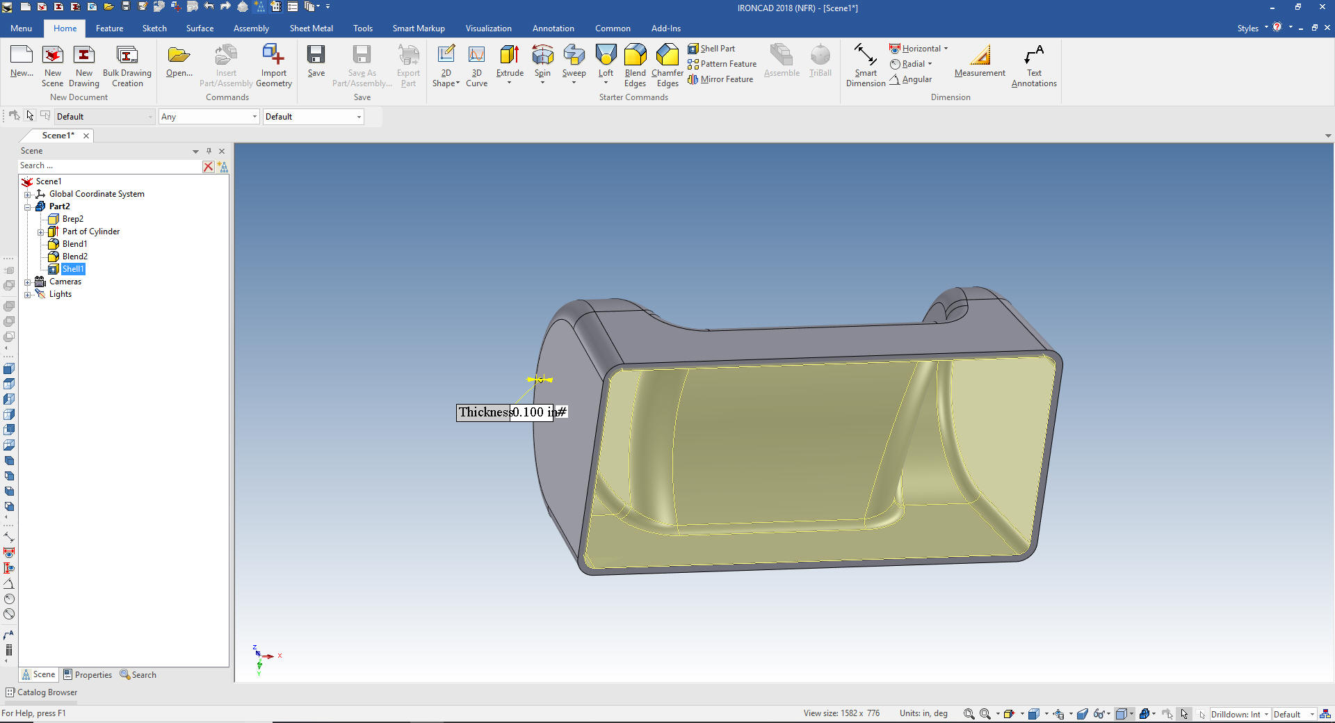 That will get you familiar with the direct edit functionality always available with a push of the right mouse button. Productivity increases up to 5x on conceptual design and up to 10x modifying design. Change can actually be fun, IronCAD is the most fun you can have with 3D CAD. Again please download IronCAD and start experiencing the increased productivity. Today, engineering is a bottle neck due to the time consuming design paradigm of the major 3D CAD system. IronCAD can increase productivity on conceptual design 5X and with modifications 10X. This translates to real cost savings. Is 3D CAD Productivity an Oxymoron? For more information or to download IronCAD Here are some exercises that you can do. They will introduce you to more Streamlined Sketching and Feature Based Modeling. IronCAD vs Fusion 360 IronCAD vs Solidworks Again If you have questions please skype me. I am usually available from 4 am to 2 pm weekdays. Weekends usually from 4 am to 10 am. Maybe later, if I have some work, you can always give it a try. Again please send me an email so I know who you are: joe@tecnetinc.com Lesson 6: IronCAD Configurations - Managing the Single Model Environment |
|
Please feel free to stop by our website below for a variety of articles on the State of our Industry, interesting articles on 3D CAD Productivity and a few of our projects!
Viewpoints on Today's 3D CAD and
Engineering Industry
TECH-NET Engineering Services! We sell and support IronCAD and ZW3D Products and
If you are interested in adding professional hybrid modeling capabilities or looking for a new solution to increase your productivity, take some time to download a fully functional 30 day evaluation and play with these packages. Feel free to give me a call if you have any questions or would like an on-line presentation. For more information or to download IronCAD or ZW3D Joe Brouwer |

TECH-NET ASSOCIATES | RENDERING OF THE MONTH | CAD•CAM SERVICES
HARDWARE | TECH TIPS | EMPLOYMENT | CONTACT