Reusing Existing CAD Models for a New Product! Oh! Oh! PHASE II 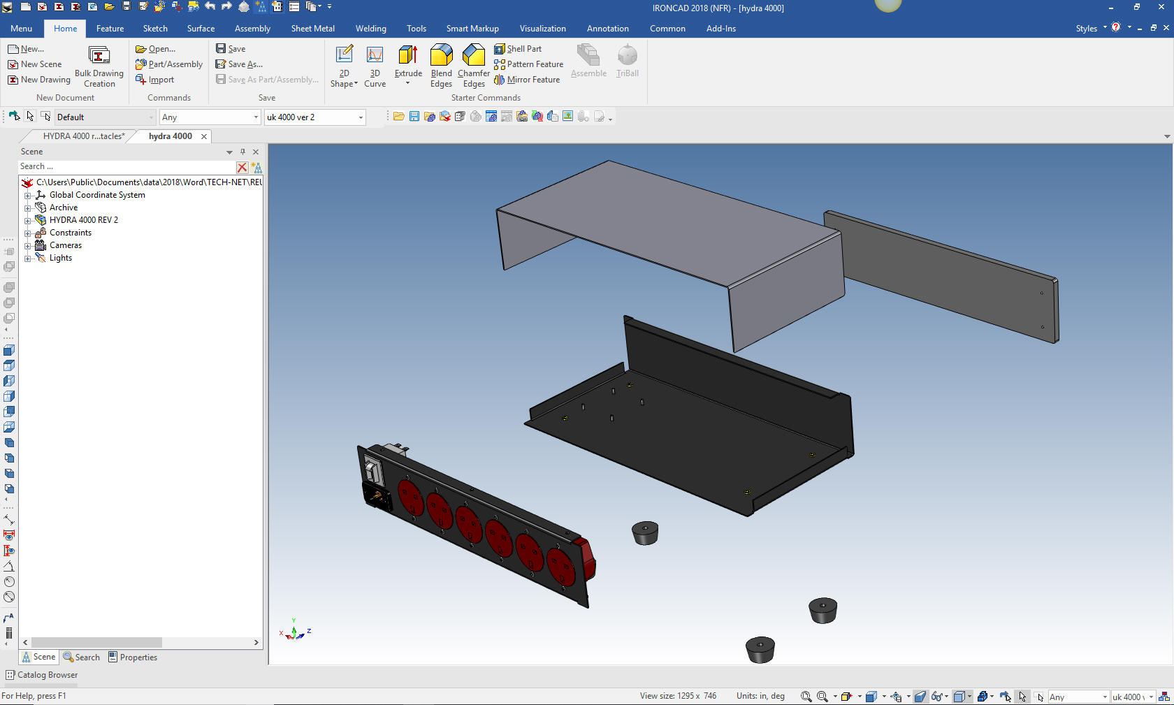 |
|
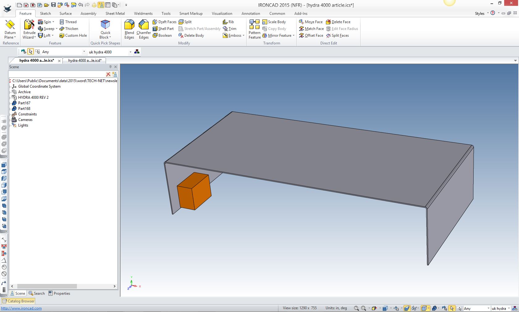
Please View Reusing Existing CAD Models - Phase I The customer reviewed Phase I. He decided he wanted to have it made up of three parts eliminating the cover and base replacing it with a cover, base and end plate. The end plate will now serve as the basis for the receptacle modules. This will be a much easier conversion since we will not have to resize many of the parts. First thing is to create the cover and base. We will drag and drop a block and resize it. To create a block as a new part we use the right button and drag it from the standard catalog on to the existing assembly and will be given the option to create it as a new part.
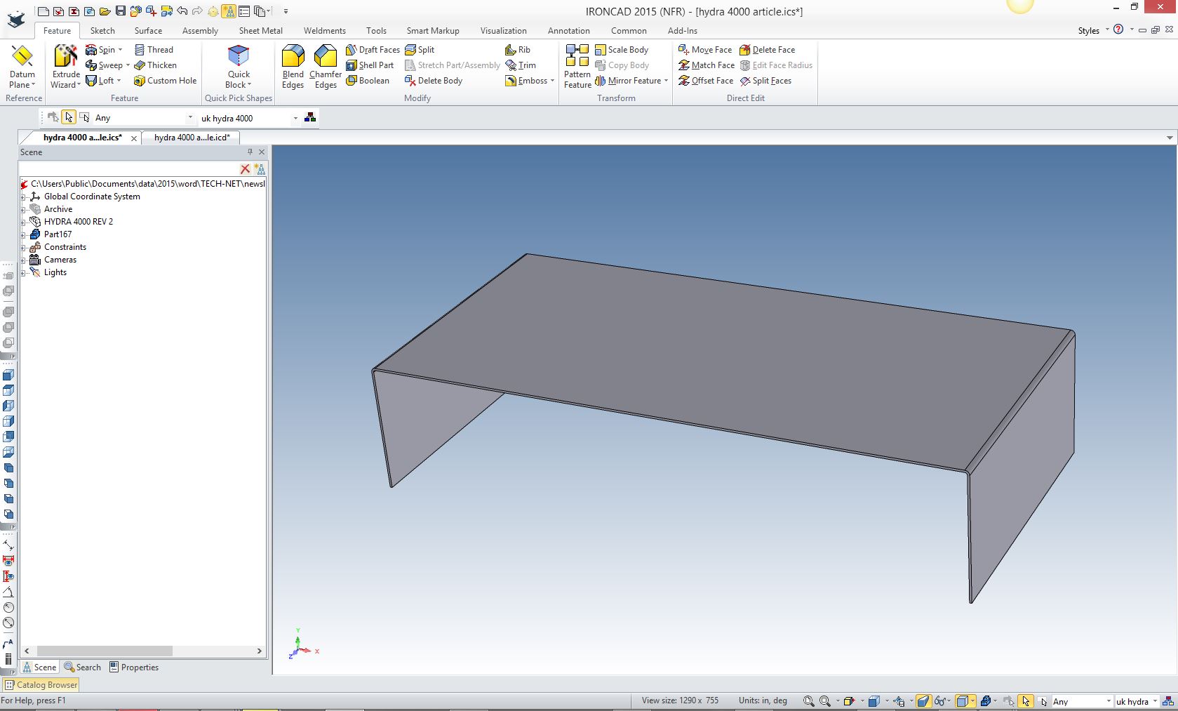
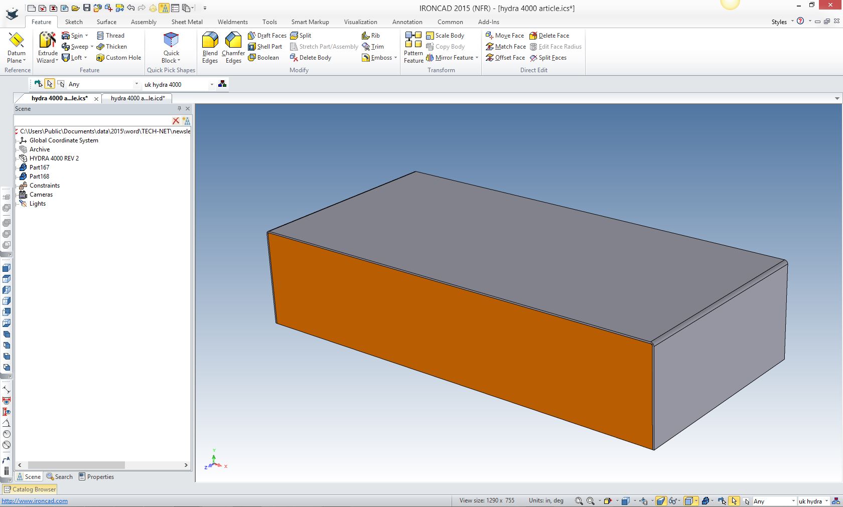
We will hide the front plaque and pull the block into shape.
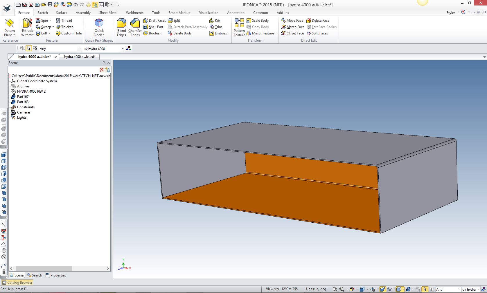
I created the blends and shelled the cover.
Now we create the base by creating another block. I changed color to clarify the process.
The base block
Add the blend and shell the base
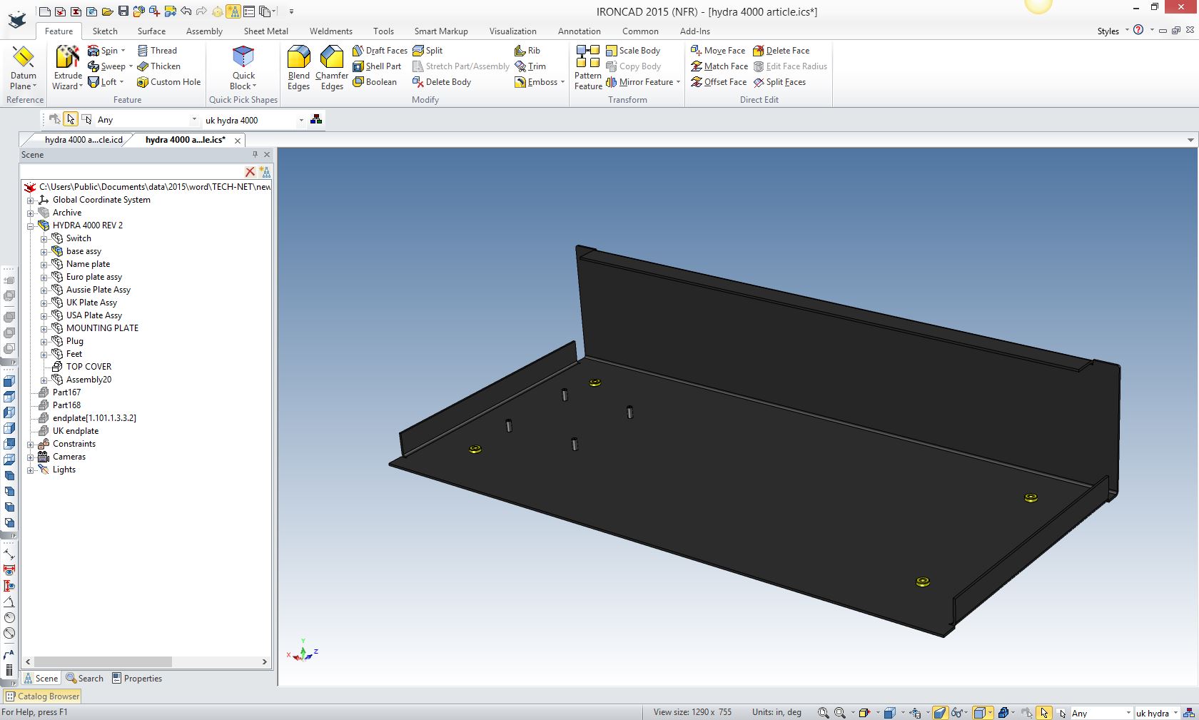
We need to add the mounting flanges and fasteners and complete the base assembly
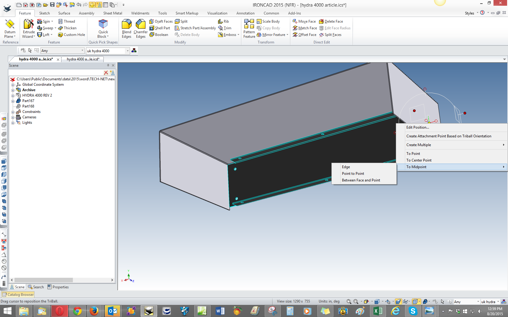
Now we need to move the end plate to the other side. We now just mirror copy the existing end plate. We move the triball to the mid point on the edge.
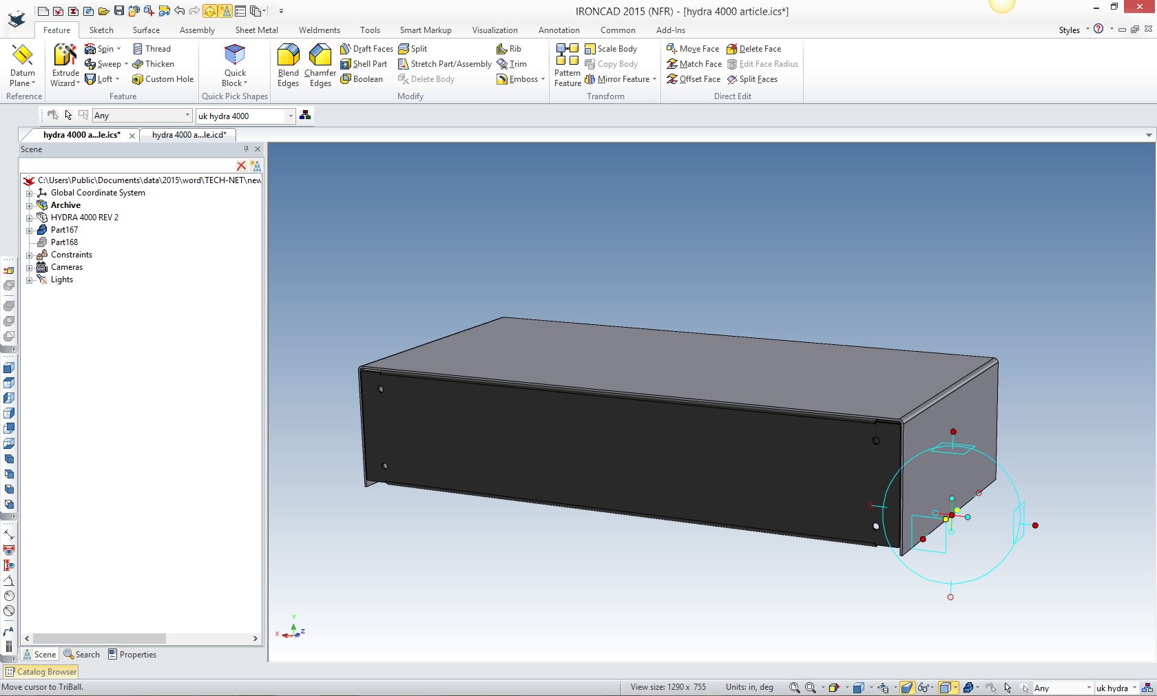
We now will mirror copy the end plate
We have to move the bottom of the end plate to match the base.
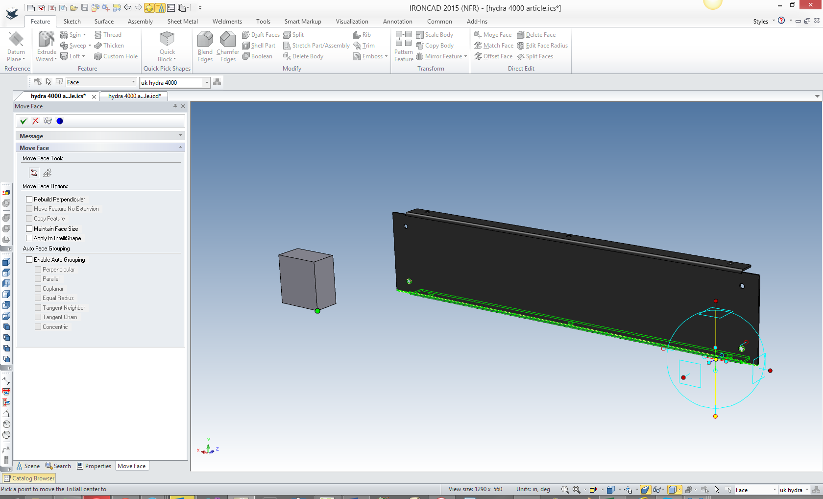
Now to stretch the end plate. I create a block that matches the inside bottom of the base. Note: Again IronCAD has now added the from function in the Triball, simplifying the above step.
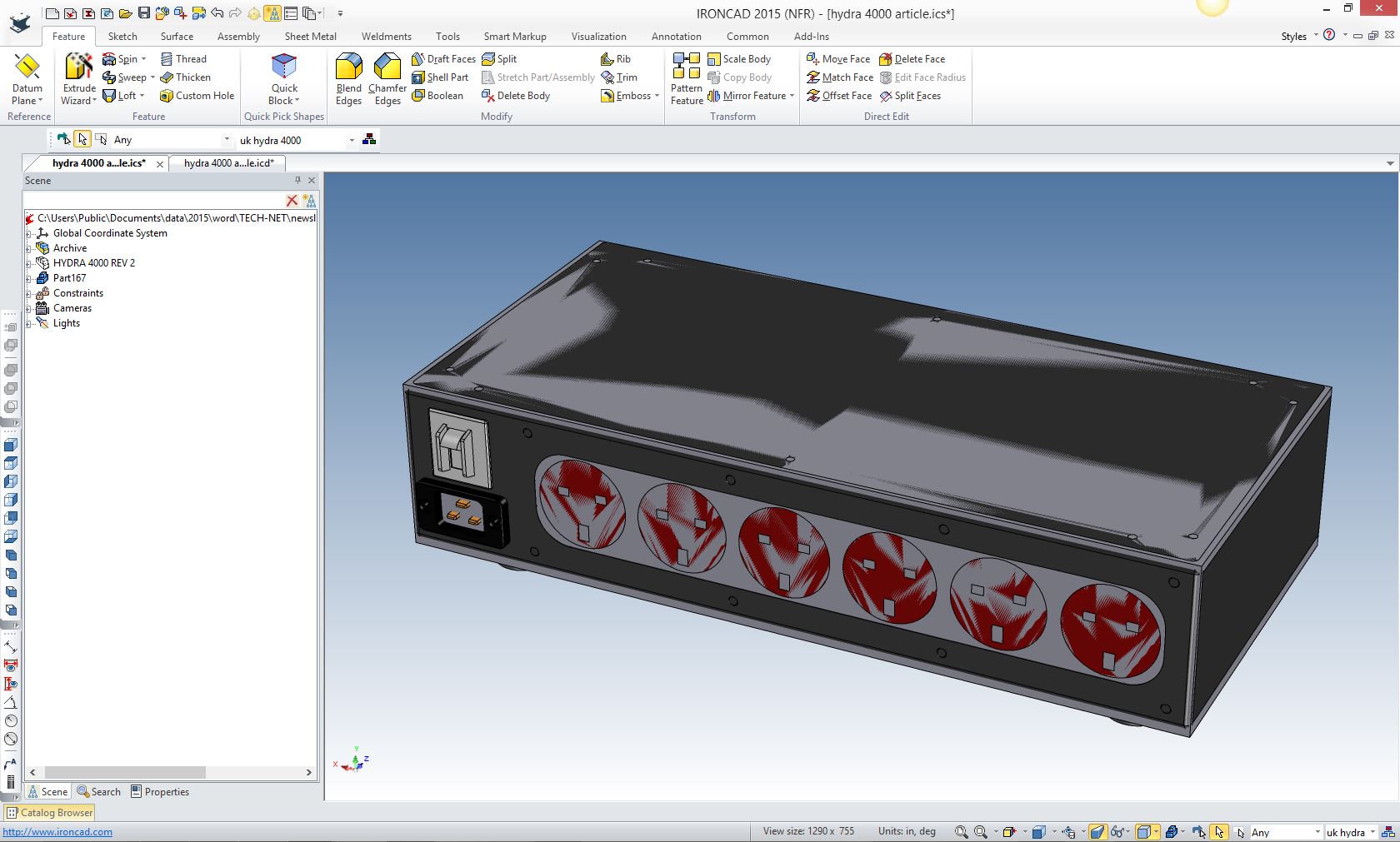
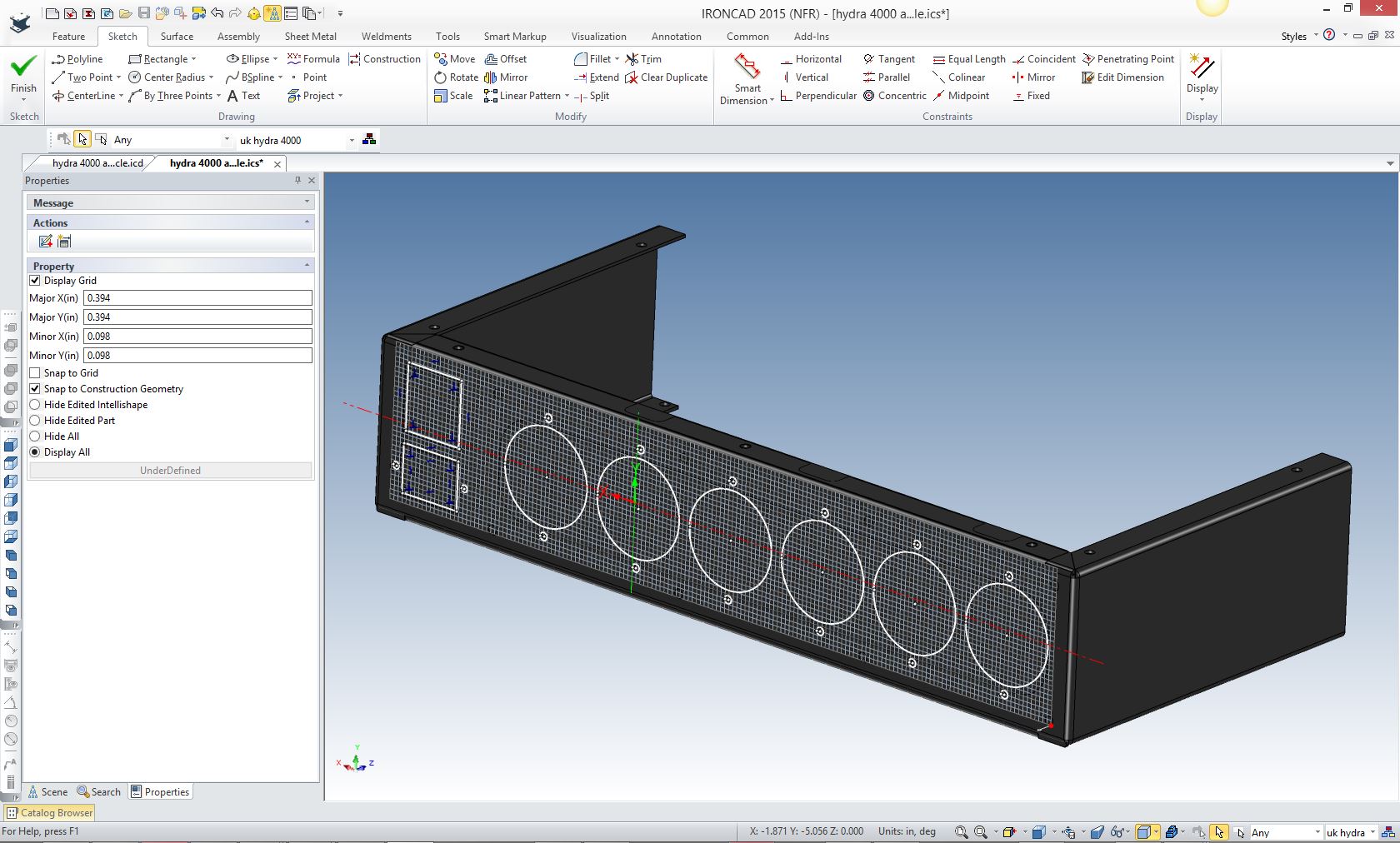
We will now prepare the end plate for the UK receptacles. We create a sketch and project the required shapes to extrude.
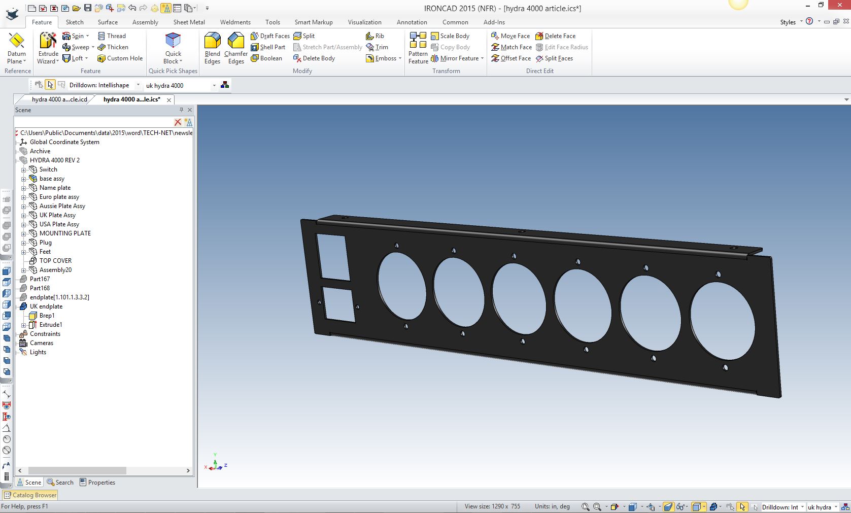
Now to complete the extrusion and remove the existing mounting holes
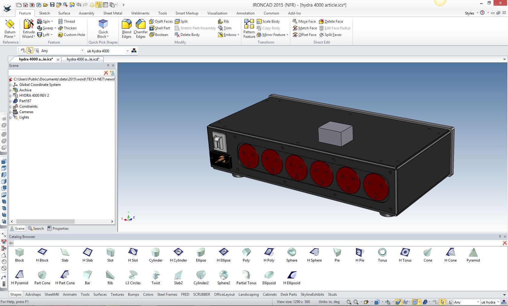
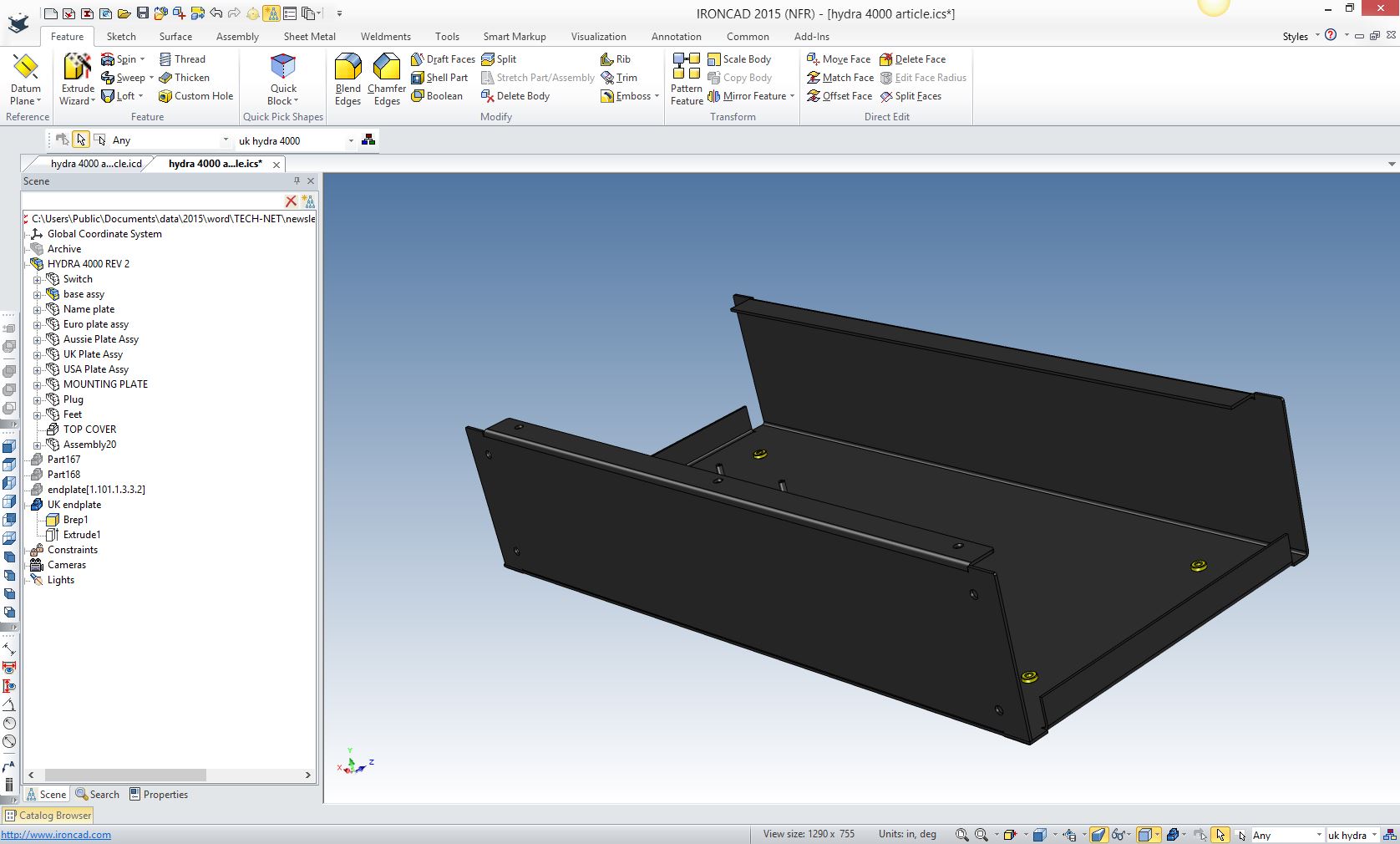
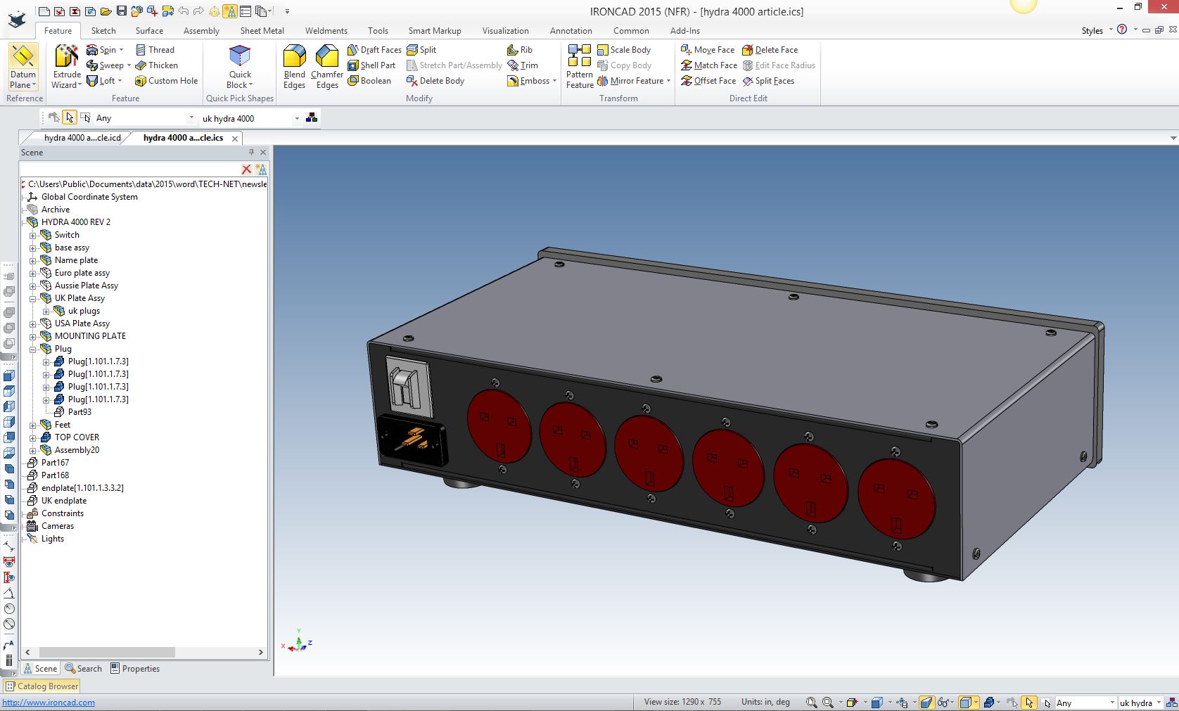
Now we just show the rest of the components. The plug, switch and receptacles never had to move. Another configuration in a couple of hours. How long would that take in a Pro/e Clone? Remember I never used any history. I know, I know, How can that be?? Since the basic enclosure was completed all I had to do was modify the the new mounting plate for the other configurations.
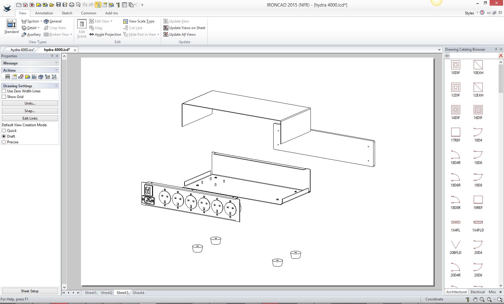
Here is the explode view created in the documentation module.
When we completed the project I created completely detailed documentation and sent the models and the documentation to the supplier. Think about this. We are talking hours and hours of time saved. Download and import your assemblies and try it for yourselves. If you are in management realize that you can have projects done in less than half the time. No, the designers have no incentive to move to a more productive 3D CAD system. They are totally happy with the status quo. I have seen the wasted man hours with the SW clones in overly complicated modeling techniques. It is too bad this level of design complexity has become the normal process. Give me a call, I can truly shorten your design to manufacturing time in all aspects, from 3D modeling to engineering documentation.
Joe Brouwer
TECH-NET Engineering Services! If you are looking for a new solution to increase your productivity, take some time to download a fully functional 30 day evaluation and play. Feel free to give me a call if you have any questions or would like an on-line presentation. IroncadFour Functions that Increase 3D CAD Productivity!! IronCAD vs Solidworks and the Pro/e Paradigm Joe Brouwer 206-842-0360
|
TECH-NET ASSOCIATES | RENDERING OF THE MONTH | CAD•CAM SERVICES
HARDWARE | TECH TIPS | EMPLOYMENT | CONTACT