|
Why MBE/MBD/PMI Will FAIL Part II | |
 "Engineering's only purpose is to make available complete, concise and unambiguous documentation to manufacturing." Why MBE/MBD/PMI Will FAIL Part l So here we go again with a promotional white paper, this time from PTC.
"Explore how reusing rich 3D models can help you manage complexity, maximize customer value and move ahead of the pack"
"Rich 3D
model?" MBD does nothing of the sort!
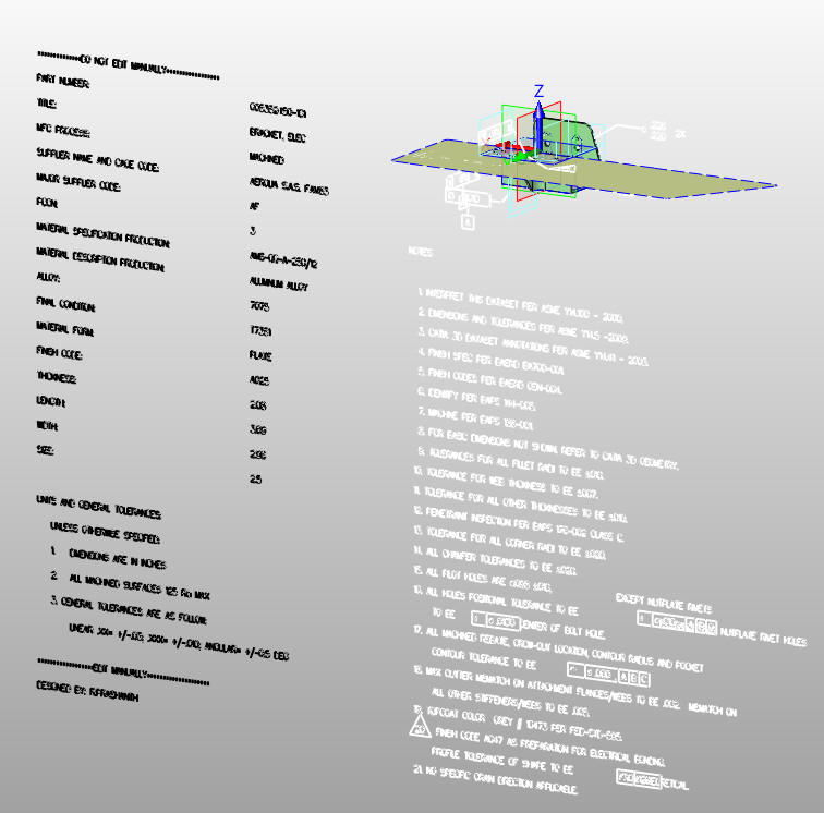
"Complexity?" You haven't seen complexity until you have seen a PMI. "Maximize Customer Value?" Buy our software! "Pack?" Trust me there is no pack! How could anyone buy this marketing garbage? I can tell you it is not the frontline engineers and designers. Download and peruse this ridiculous presentation of the advantages of MBD! Why are the major CAD vendor pushing MBD? The PMI (Product Manufacturing Information) is in a native file of the CAD software. This ties you to the specific CAD program forever. PTC has to justify moving you to subscription only. This is a feature they are demanding that you move to, is only found in the latest versions. I suggest you stay with the old perpetual version and continue to use a much more user friendly and cost-effective alternative I describe below. No need to upgrade or buy special software solutions. With the alternative you even have the option of moving to another system. There are many 3D party programs now being offered to make this convoluted system work, from PMI to AID conversions, Quoting Software, Viewing Software, Translation Software, Validation Software, etc., all costing thousands and adding more processes and learning curves. Yes, they all have to have maintenance contracts to make sure they are compatible with your CAD software. We have to believe there is no one in charge of evaluating the engineering process. Just buying what ever the major CAD systems are selling. MBE offers no advantage over the alternative. The cost of the alternative? Nothing, and offers much more flexibility in the way you manage your documentation. We can create a standard document control system for all companies no matter what CAD software is used. Here are two production PMIs from two different companies. Both are not built on any standard. This one is a complete file and almost stands alone. You can see extraneous information that would only confuse the supplier.
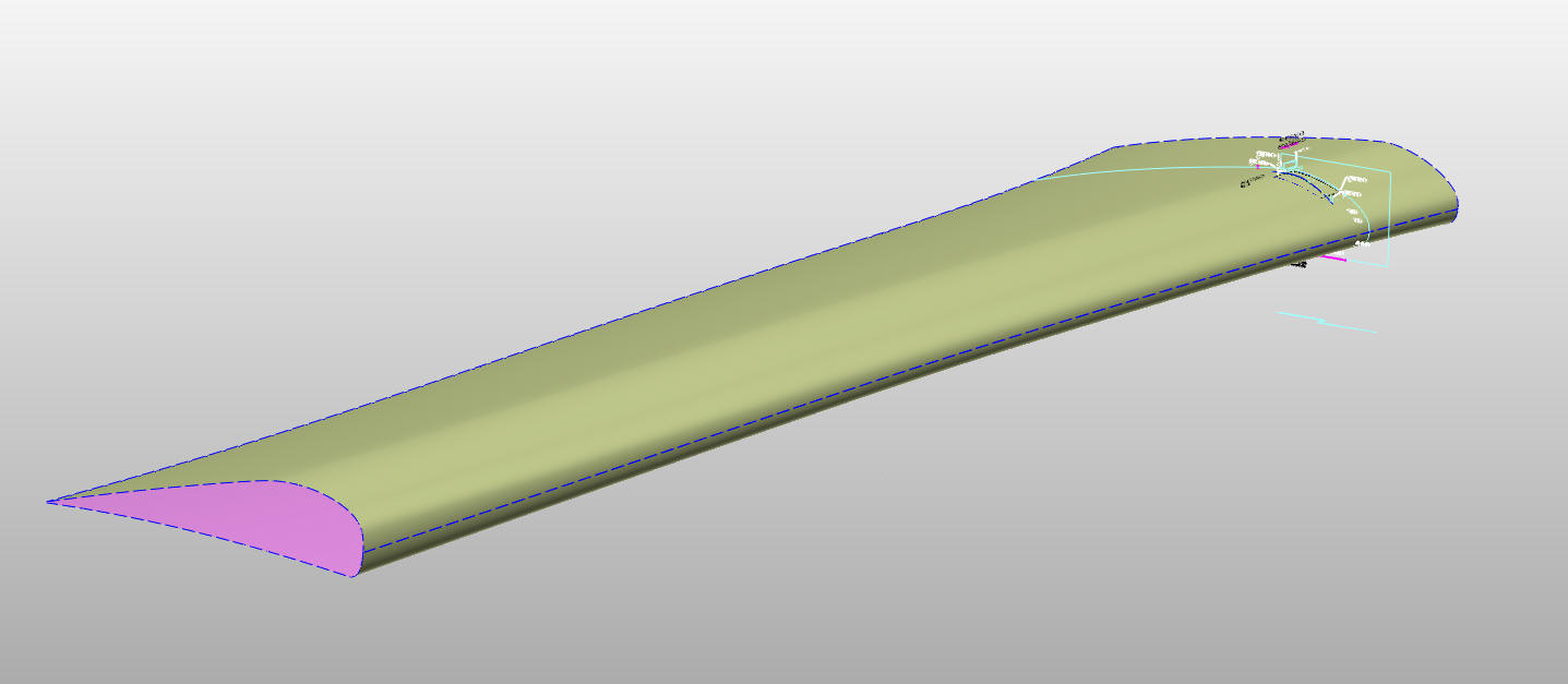
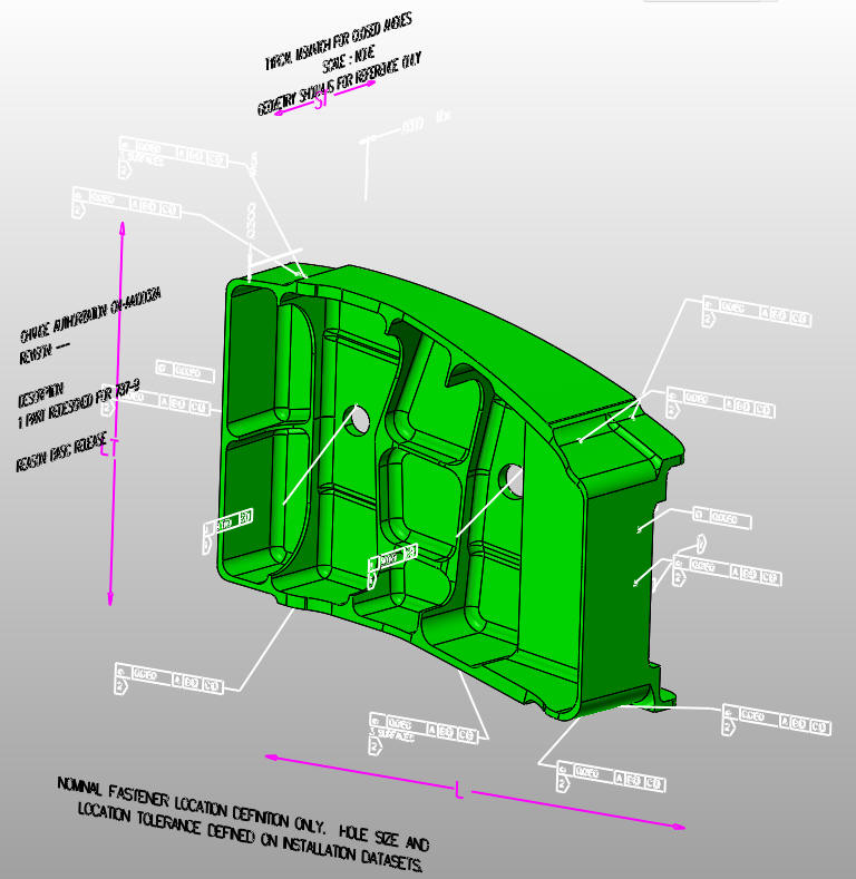
This one indicates "geometry" is for reference only, yet it was sent to a supplier as the released part. I have no idea what the released engineering documentation package consists of. Notice that notes are on two different planes. Trust me, this is not ready for prime time. These two are very simple parts. This includes much more extraneous information. Why is it there? Only for engineering to understand the mating surfaces. But why send it to the supplier? The supplier should get the net part only, anything else can cause confusion.
This is what the supplier has to get it to. ZW3D makes it easy by separating the wire frame, surfaces and solids. All being included in file.
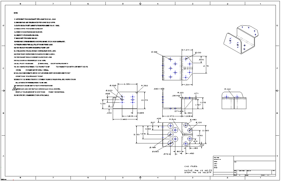
There you go. Viable engineering documentation? It is NOT! Here is the top PMI as an AID. I can guarantee it is much easier and take less time than the original PMI. Those that say it takes longer are lying to you. The AID becomes more viable as the part gets more complex. Applying tolerancing with the AID is much easier. The excuse that the new millennial engineer is too stupid to understand an AID is incredibly condescending. Is their IQ less than the engineers and draftsmen of the past? A short drafting class is all it would take. You decide which is more clear and easier to work with. This is an associated information document and "Travels" as a PDF with the 3D model shown below. Even though I recommend complete detailing (dimensioning) the part for checking for errors is it not created to stand alone. Another important fact: If it is difficult to detail (dimension) it will be equally difficult to manufacture. But what does it take to read a PMI? Native software or a 3rd party translator. I am using ZW3D here which is fantastic. There are no free PMI readers. We are talking about 5 major CAD companies using the native file for the engineering deliverable. All being at different version of release. Now for the AID and Model? The AID released as a PDF and the model can be in the native CAD or neutral format (STEP, Parasolid, ACIS, etc). You need an Adobe reader and a compatible 3D CAD systems which they all are! This is what I send my suppliers. They require it. But if you are working a large aerospace or automotive company they tell you what you need to make the parts. We need a neutral file format for the model. The native file can be corrupt and no one finds out until they try import it into the CNC program. We need a program that scrutinizes the model for producibility prior to release as the neutral dumb file.
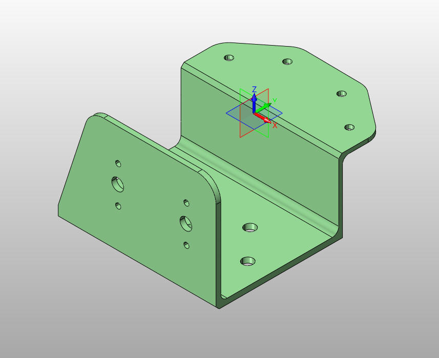
Here is the model. Yes, it stands alone. No extraneous graphics, just the net part. This is actually an assembly with nut plates. I don't know when they get installed. They are referenced in the notes. The machine shop would install the nut plates so it is a bit confusing.
What is the alternative to this idiotic format? I will try to keep this bit of history short. In the beginning the original selling point of 3D CAD was to create faster "drawings". Now these were not drawings but when plotted they looked just like drawings. How were they made? They were created in a documentation module. No, not a drawing module since nothing was drawn. Views or instances of the 3D model were placed inside a border using correct orthographic projection and then dimensioned (detailed), notes and other annotation are added. These documents were created to the drawing standards used for centuries. These were not drawings! And they surely were not 2D drawing, what ever those are! LOL The first 3D CAD systems were 3D wireframe. The only use for the model was the documentation. Around 1988 the wire frame model was made available for 2.5 Axis CNC. 3D surfacing was developed and supplied surfaces for 3 Axis CNC. Now the model was sent with the documentation to the machine shop, sheet metal house, mold design or any supplier that could directly access the model. The documentation was not a drawing. A drawing is a document made up of separate non-associated orthographic view. These new documents were much, much easier. Soon solid modeling showed up making this process much more productive. Since these were not drawings we really need a better description than "The document that comes out of a 3D CAD system". Many used "2D Drawing" for anything that looked like a drawing. Most were ignorant of these two separate totally different processes.
Boeing draftsman using Catia and CADKEY were calling them flat files. They were sending the model and a print of the flat file to the suppliers. By mail!! Remember PDF did show up until the turn of the century. Flat file is just not descriptive enough. I have coined these: AID (Associated Information Documents) So this shows you that MBD was here years before. You didn't think we thought of 3D drawings? When CADKEY developed standard and user defined views in 1988, we started playing with dimensions in 3D space. We realized they were only functional for the simplest of parts as illustrations and discarded the idea. Sadly they still are. I have never seen a complex part. All the examples are very simple. The reason? Those that promote it never use it. Short enough??? Here are the talking points. Let's take them apart. "Model-Based Definition (MBD) is a prerequisite for achieving Model-Based Enterprise, but the realities of implementing MBD have traditionally been fraught with challenges. Today, many of the hurdles that were once stumbling blocks for adoption of MBD have disappeared. Advances in technology and standards are bringing us to the point where MBD will become a preferred way of design. What are the "So called Advances in Technology and Standards"? They cannot tell you. There are not applicable standards at this time. Let them show us production PMI's. I showed you just two. Model-Based Enterprise does not need the PMI. We did it for decades before Dassault sold this scam to Boeing. "Are you ready?" How much money do you want to waste? This eBook focuses on: The limitations of using 2D drawings "What’s the problem with 2D Drawings? Historically, engineering processes have been centered around 2D drawings. Drawings are the master records and have been the primary product definition deliverables for innumerable years. Most of Engineering, Manufacturing and other downstream users have relied on a physical or a digital representation of 2D drawing to convey form & fit information that’s required to drive manufacturing processes. With the advances in technology and the ongoing business challenges to shorten product development cycles, 2D drawings fall short in a number of ways." This is coming from PTC? These are the folks that forced us to create AIDs in 1988. They didn't even include electronic drawing functionality. Why? They wanted the user to create 3D models only. Then create the AIDs. Nobody is using "2D Drawings" today that are using the major 3D CAD packages most are creating fully detailed AIDs . Why are they still pushing a concept of "2D Drawings" that has been gone for over 30 years?
3D modeling moved the documentation to the
I really don't know what they mean by "2D Drawing", plus all drawings are 2D.. 2D Drawings fall short in the following areas: • Explosive growth of mobile technologies and the future of affordable 3D technologies. 3D visualization is becoming mainstream. What the hell has mobile technologies have to do with engineering. There is no way to even effectively utilize the engineering documentation in mobile technology. Hell you have to have a special viewer to even view the PMI. The tablet is of marginal use in manufacturing. A printed AID offers a much more user friendly document that can be marked up and sit next to the planner, mechanic or CNC programmer. 3D visualization has been mainstream since the beginning. I was introduce to 3D CAD with Computervision CADDS 4 in 1982. • 2D drawings are generated from 3D models. Its time consuming to re-create drawings and is a wasted effort Again we do not create drawings, we create AIDs and they are much simpler than the convoluted PMI. Only someone who has not done either would make this ridiculous statement.
• 2D drawings alone are not adequate to capture the innovations that engineers create. Hence, complete definition of the design must be stored in multiple data sources that are disconnected from the 2D drawing The AID and the model have traveled together since the model became available as a pattern. We are now getting into the real problem. Data Management. PLM found that keeping the model and the synchronized document an impossible data management problem. Of course their big mistake was trying to use the native CAD file as the engineering deliverable. All of the companies were delivering the documentation outside the CAD system as a model and an AID prior to PLM. The PLM gurus are the most ignorant people when it comes to engineering documentation. They really don't know the process.
Engineering Documentation A Primer for the PLM Guru! Here is Oboe Wu, manager of Solidworks MBE efforts. He has no clue that the model and the AID always travel together. • 2D drawings are not suitable for wide-spread collaboration across geographical barriers What the hell does this even mean. Let me send you a model and AID as a PDF by email or any other media that can handle digital data. Geographical Barriers?? Most of my work is done telecommuting. In fact I was telecommuting from Southern California to Square D Corporation using a phone modem in 1988. • 2D drawings are more prone to interpretation errors and result in design non-conformances and data inaccuracies. This is totally untrue and only could be said by someone that have never created a 3D model and AID. Again you can see the incredible lack of understanding of what they even mean by "2D drawings" • Young engineers of today are not the same as the young engineers of yesterday. Creating 2D drawings for them is like a step backwards as they “think, see and play in 3D” This is just plain stupid. Again we don't create 2D drawings. We don't do any drawings. Young engineers can be educated in the drawing standards to create the AIDs. I have trained many young engineers to draw when on the drafting board. I have trained many engineers, young and not so young to create AIDs. Most young engineers don't even know 3D CAD will be part of their job. Play? Trust me very few play with 3D CAD. Most only work on it at work. Many using the Pro/e clones find it tedious work.
I would get a notification of those that would download IronCAD. I noticed the .edu on the emails. I would call them and they would tell me the professor would request they download and use IronCAD for the class. I would try and sell them a fully functional educational seat for $124.00. They would laugh and say "I will never use it". I am sure many are today.
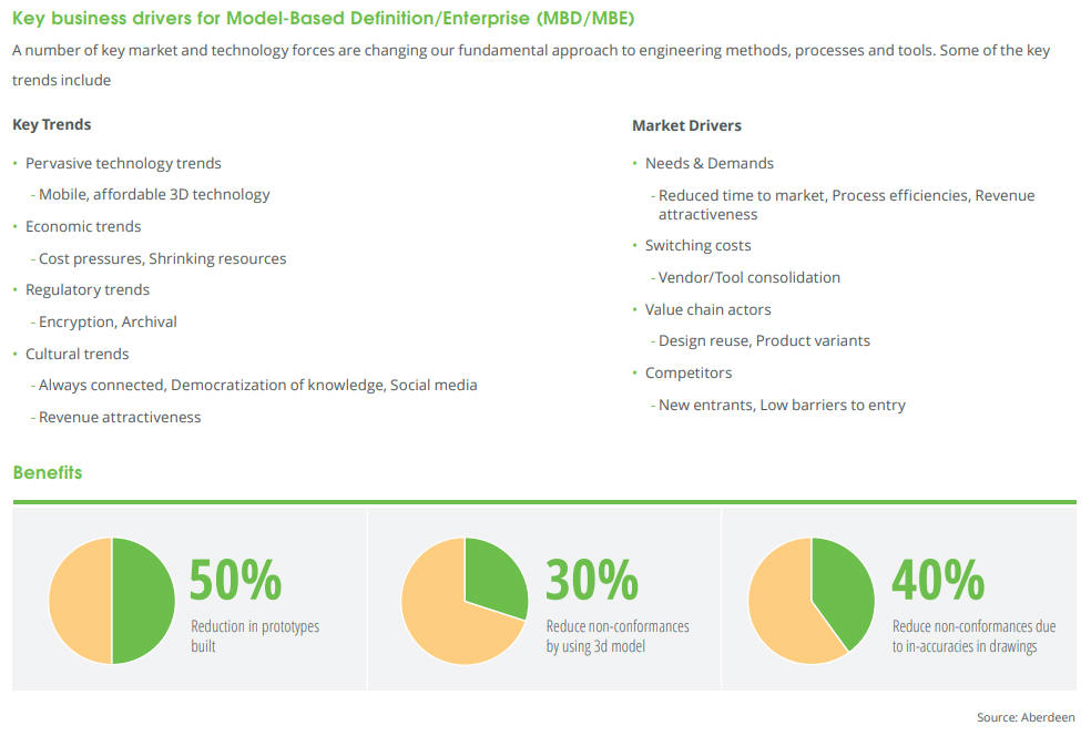
A Key Business drivers for Model-Based Definition/Model-Based Enterprise
These statistics are not base on real life engineering. I have personally supporting manufacturing companies using 3D models since 1988. I sold CAM (CNC) products since then. Surfcam, CADKEY CNC and ZW3D working closely with MasterCAD, Smartcam and others. When they reference drawings they are talking about drawing, from the board or out of an electronic drafting package (Autocad), not the flat file or AID (Associated Information Document) generated from the model and travel together. The PMI (Product Manufacturing Information) requires much more expensive delivery solutions and offers less usable information than the fully defined AID which is delivered as a PDF. You need a seat of the native software or a 3rd party translator. Our ZW3D product will read and utilize the PMI file from NX, Catia, Creo and Solidworks. What does the model and AID alternative cost? Nothing. They just need any 3D CAD program and an Adobe reader. How the MBD methodology simplifies complexity, eliminates inaccuracies, reduces errors, & cuts down costs. It costs a fortune to implement. The is no simple about it. A model and an AID is simple. It in no way eliminates inaccuracies only thorough checking does that. There is no way a PMI reduces errors. Its obscurity actually increases the possibility of errors. This is the most costly process engineering has every developed. Engineering based on the drawing was much more productive. All we did was add the 3D model as a pattern. Delivering a 3D model does not assure correctness. I have been working with suppliers for years and the 3D model has delivered more costly parts than the days of the drawings. A few suppliers have told me they had to tell Boeing and Airbus the parts could not be made. When you create a fully defined AID you take a second look at the part for errors or even a better design. The scrutiny of the part gives you more knowledge of that part compared to the PMI. Many designers actually create a fully defined AID to check their work then create the time consuming PMI required by those that sit in ivory towers that have never evaluated the effectively of MBE. Here is a comment from a MSME PE on this article when I posted to Linkedin. "The big problem is, any failure will be blamed on the responsible engineers and not an unworkable system. MBE is already being backstopped by drawings in many organizations that are forced to use MBE, but the drawings are frequently not in the release control process because they are not the "primary" data driving fabrication. A fine mess.." Going Model-Based – Where do you start? Do not start with any of the major CAD programs. This is a fraud that locks you into their product. You want an effective engineering documentation solution? You just need to get your engineering documentation out of the CAD system and into a folder that includes the model and the AID as a PDF. Most smaller companies already do this. The goal of engineering documentation is after it is delivered to manufacturing and archive you never see it again. The cost of MBE puts it out of reach of the smaller companies. They don't know how lucky they are. I have taken a project done 10 years before and modified it. I just looked into the customer folder and found the released engineering. Yes, engineering documentation is stored forever. It should be stored in an easily accessible system. When the authority was the drawing is was in the form of blue prints, available at a counter or cabinet. Yes, sorted by part numbers. At Boeing with the amount of drawings they went to a microfiche system. How far back did the keep the drawings, I personally worked on a drawing for the KC-135 (basis for the 707, 727, 737 and the 757 dated in the early 1950's drawn on linen. Today, PLM systems are very convoluted and the IntoTech and PLM gurus lack of knowledge of engineering documentation has made a very simple document control system a data management nightmare. It is just too simple. You have an arbitrary part number and a name. I describe an ultimate cloud based document control system that can handle any form of documentation, even the idiotic PMI below. The native CAD files should use an effective PDM system inside the CAD system. Again, these files should be archived. The designer should first look to the released 3D model (native or neutral) file and the AID. The AID should include the originating 3D CAD file number and name. I have even developed a system to have that information on the model. Imagine, all of the original part information on the model no matter what format it is delivered. Many of you may not know that most suppliers don't even have a seat of the native software of the company they are working with. Many can read the native files or demand a STEP, IGES or other neutral file format. Part and Document Tracking If the model gets separated from the PMI or AID there is no way to know what it is. It is the file name consisting of a part number and a description. This happens many times when it is converted to a usable format for the CNC or other CAD system. Here is a system that includes all of the information of a title block.
If this simple solution was standardly used imagine how it would eliminate many errors by not having the latest part revision. The Embedded Title Block! A PLM Solution! Engineering Changes How does MBE handle changes? This is by far one of the most expensive parts of MBD. You discover an error, you have to fix the model directly. Now you have to released a revision to the part. With complex history only systems how do you know you have not altered another feature? Now, you would need a compare program to see the difference of the modified part as compared to the old part. Visual inspection is not adequate. This opens the door to Murphy to cause a multitude of problems that will be compounded and not easily found. With an AID any modification is noted in the documentation showing the affected dimensions and the change sticks out like a sore thumb. This is one of the reasons for a completely detailed AID.
The ADCN (Advanced
Drawing Change Notice) vs MBE Effective Document Control Today PLM is failing to manage engineering's documentation. In the past it was a standard system based on the drawing. It is shocking that the PLM gurus never studied the past system. All we did was add a 3D model. For the first 15 years the CAD information was done the same as the drawing except the 3D model was referenced on the AID. That is what indicated it was an AID. We need a system that will handle all forms of engineering, drawings, AID, PMI and any supporting documentation we deem necessary all in one, what I like to call, documentation bucket. Here is a great cloud based document control system. We have it with Onshape. With just a bit of modification we could have all of our engineering documentation, including a view of the 3D model, available on any browser, Apple or PC. I can tell you the first one that provides it will make a fortune. Give me a call and we can set it up. The Ultimate Engineering Document Control System
Conclusion Now that you have a good understanding of how the MBE PMI works lets take a look at a situation the powers in charge never thought of.
All of these are solved with a simple and fast AID. There is no advantage to the PMI, it is not any more usable than the AID with the model. | |
|
TECH-NET Engineering Services!
If you are interested in adding professional hybrid modeling capabilities or looking for a new solution to increase your productivity, take some time to download a fully functional 30 day evaluation and play with these packages. Feel free to give me a call if you have any questions or would like an on-line presentation. |
TECH-NET ASSOCIATES | RENDERING OF THE MONTH | CAD•CAM SERVICES
HARDWARE | TECH TIPS | EMPLOYMENT | CONTACT