3D Modeling Techniques
ZW3D vs Solidworks Lesson
Seven
Streamlined Sketching Defined
I saw some Fusion 360 exercises online and I decided to compare
ZW3D. It quickly turned into a study in modeling techniques. I have created
many comparisons to Fusion 360, Onshape, Solid Edge, NX, Creo,
Catia and Inventor
lessons to show the difference
between ZW3D and my modeling techniques. I found the presenters working
identically wasting massive amounts of time
with overly complex constrained sketching procedures. I was so unimpressed that
I decided to model the parts or assemblies showing my modeling techniques plus 's superb design system.
3D Modeling Techniques Defined
Many of these modeling techniques can easily be implemented even
within their existing system. I call it Streamlined Sketching and
Feature Based Modeling. Please review a few of the above ZW3D
comparison lessons, there are some very stark differences.
This is my second lesson that is based on a comparison between KeyCreator (CADKEY) and Solidworks.
KeyCreator is a direct
edit only CAD system. I sold CADKEY and KeyCreator for over 31 years
in 1987 and lost the product in 2009 when they went to direct sales. I would
still be selling it today. It is a very flexible direct edit system but a
bit clunky for design. You need both history and direct edit for
highly productive modeling. I only using KeyCreator for some hybrid
modeling. But I have moved to ZW3D, it offers much more powerful hybrid
modeling functionality.
KeyCreator is level based and the level management becomes quite a
chore. Even though both ZW3D and KeyCreator are
single model environment ZW3D has much better way of displaying
and manipulating the parts, by hiding, showing and suppressing. ZW3D has just too
many advantages over KeyCreator to even get into it.
But
KeyCreator offers 2X productivity over Solidworks not only in ease
of modeling but the single model environment, even with the levels
is miles above the separate part and assembly environment of
Solidworks.
Please watch both presentation separately. The
KeyCreator presenter is touting modeling without "2D". I assume he
is talking about sketching. It is funny he says that he is doing
100% 3D yet starts with a sketch, go figure.
The Solidworks
user is stuck in the world of constrained sketching.
Sketching
Defined
As much as the KeyCreator present touts 3D CADKEY was
based on sketching, first in wireframe, then surfacing and then
solids. It did have primitive shapes but they were not flexible
enough to use in design. I see now the KeyCreator presenter has them
available and with those he easily out performs Solidworks.
Constrained Sketching is not parametric design. Many are confused on
the nature of parametric design. Pro/e allows you to program your
parts and assemblies. Which means your model is driven by
parameters, hence, parametric. It really has nothing to do with
constrained sketching. But the dimensions are designed in such a way
that they can be use as variables.
Not all sketching is equal. The Pro/e clones such has
Solidworks train the individual to constrain all sketches. But they
do not have to be constrained. I and the KeyCreator presenter uses what I have
coined "Streamlined Sketching". Both of us have never used
constrained sketching in CADKEY or KeyCreator because it wasn't
available. Years ago CADKEY release the parametric module. If they
would have stuck with it, we would all be using CADKEY "The Greatest
Hybrid Modeling System". But they didn't and now ZW3D owns that
mantle!
But that is in the past.
Sketching is part of
modeling. If you have primitive shapes that is the first option,
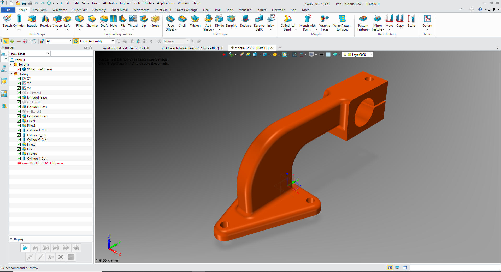
then sketching and then direct edit. I could create this part in
ZW3D by using primitive shapes but I am going to do it with
"Streamlined Sketching" and probably do it just as fast it only has
two planes and three sketches.
Here is an example where sketching was the most productive way to
make this part. This part is made up of two sketches. No 3D modeling
here and there is no way 3D primitive shape modeling can be faster.
KeyCreator's direct edit is very fast
modeling system with 2D to 3D conversions but suffers hugely as a
design product without the flexibility of history design. You really
need both to productive 3D CAD modeling.
KeyCreator easily outperforms Solidworks on this simple part
with sketching, Boolean shapes or direct edit on most design. If it was between Solidworks and KeyCreator,
KeyCreator would be my tool of choice. But both IronCAD and ZW3D can
easily out perform it in most cases. KeyCreator has some very
powerful features. Too bad it is priced so high it is a great
support tool.
Here is the drawing if you would like to
give it a try. ZW3D has an integrated drawing module, meaning it is included
in the part file. You have the parts, sub-assemblies and drawings in
one file. Imagine how that would reduce your PDM problem?
While creating 3D models from drawing is the very best
way to learn 3D CAD and maybe some design techniques it does not
expose the designer to the design flexibility necessary in design.
ZW3D is all top down due to the multi-object model environment.
Creating mating parts is a cruise. But modeling is just one aspect of a
well designed productive 3D CAD system. Solidworks
is a marginal 3D CAD system based on the dated Pro/e (Creo) history
based modeling system. I have sold this product years ago and found
it, like all of the other Solidworks clones, not productive enough
for our engineering department. We use what we sell. That gives us
the experience to effectively support our user base.
I would do a
video, but I really am not good at it. So I will show you step by
step. I will try and get ZW3D support to create one. They are
very good.
The modeling technique is hugely responsible for
the level of productivity. Those of you that are only trained in the
constrained sketching world are truly limited by not
using the freedom of feature based design, that is available in even
the most Solidworks-ish of CAD systems. If your
designers are designing in these very unproductive and time
consuming processes it might be time to review your standard design
processes. Don't have any do you?
These lessons have actually turned into exercises in
modeling techniques as compared to showing a more productive CAD
systems. Again, I say, there are many different ways to model a part.
I see with my exposure to direct edit modelers like CADKEY, I
rarely sketch like you see the Solidworks fellow doing. I have always
created my basic sketches by mostly creating offsets and extending
and trimming or. It seems to be much easier. I never put in a fillet that
can be created later. What do you think?
I am going to do this model with "Streamlined Sketching"
We are already in
millimeters. So we can start sketching.
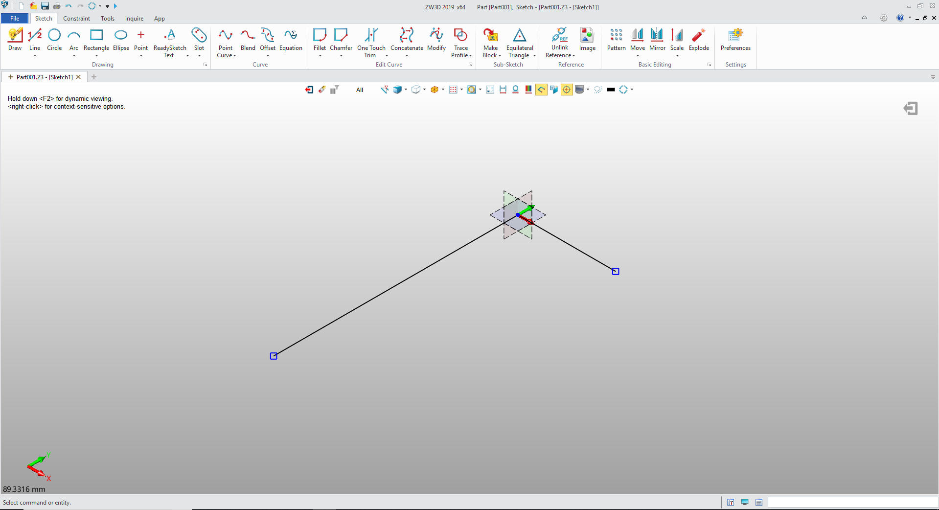
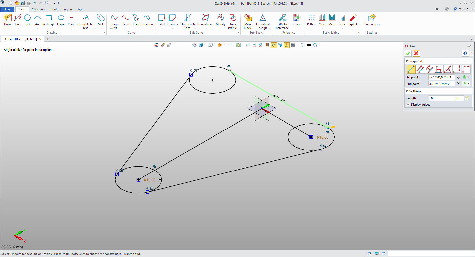
We create a vertical
line 75mm and a horizontal line 30mm.
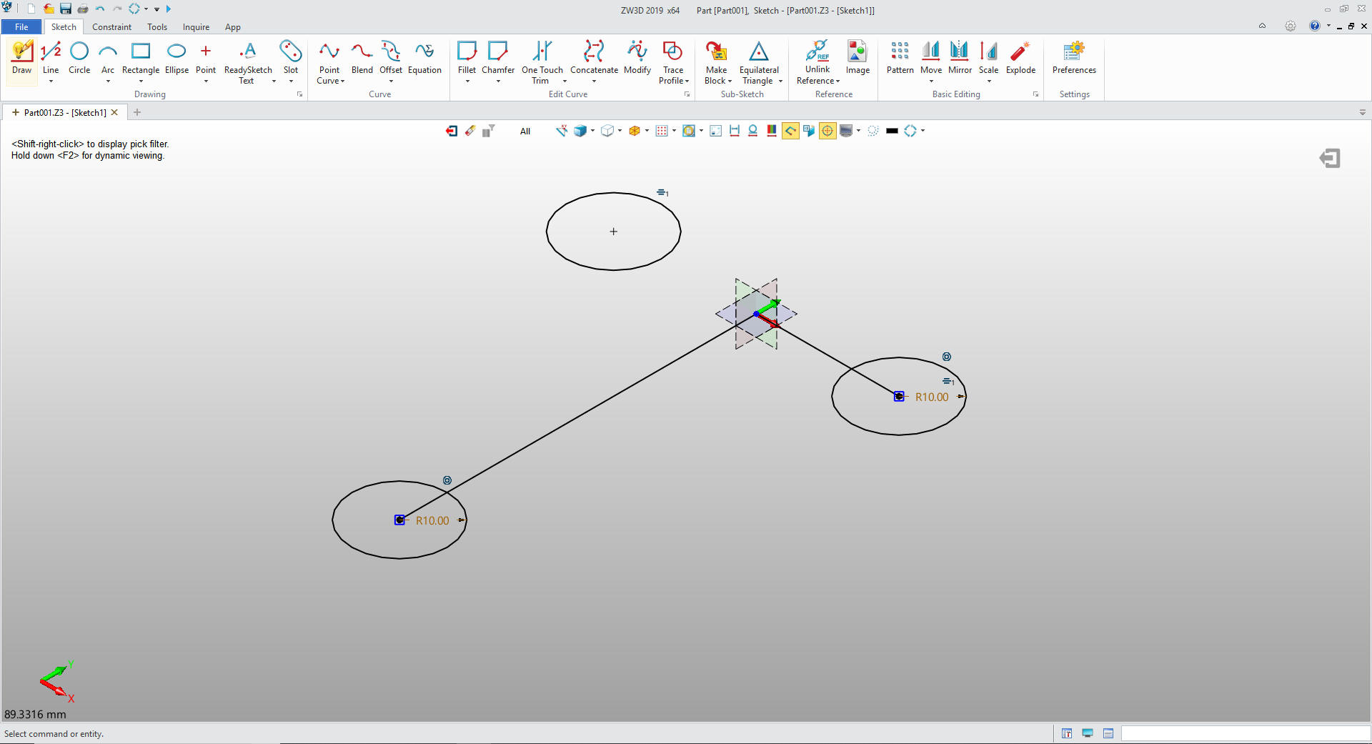
We create a 20mm
circle on the ends of the two lines and mirror copy the third.
We add the three tangent lines.
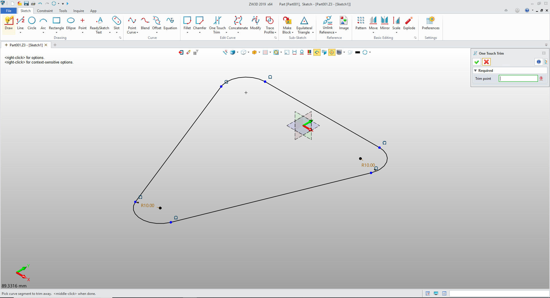
I trim the entities and I am done with
my sketch. No constraints.
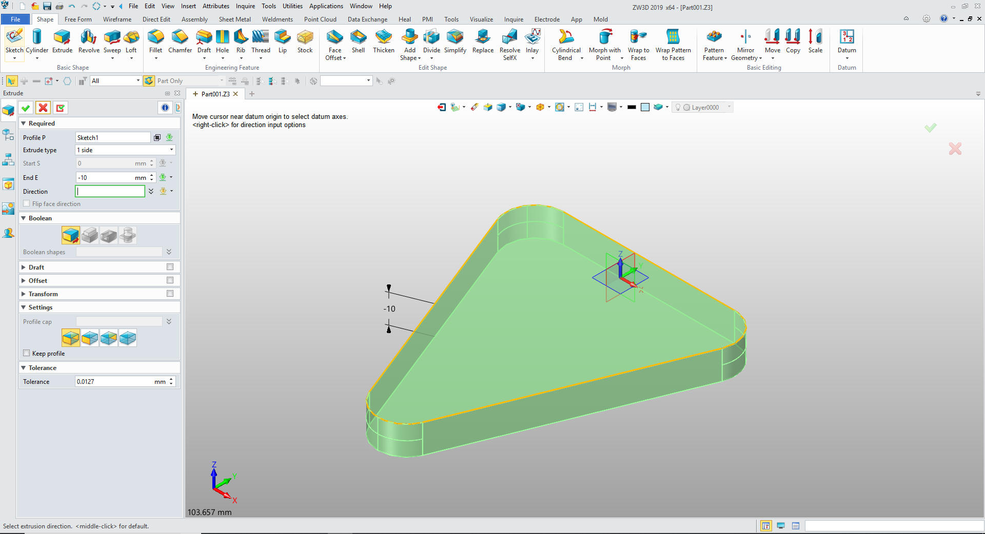
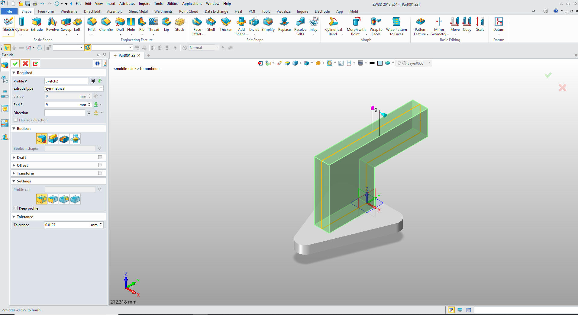
We
exit the sketch and extrude to 10mm
What
makes this an easy part to sketch is there are only two planes.
We extrude symmetrical 9mm.
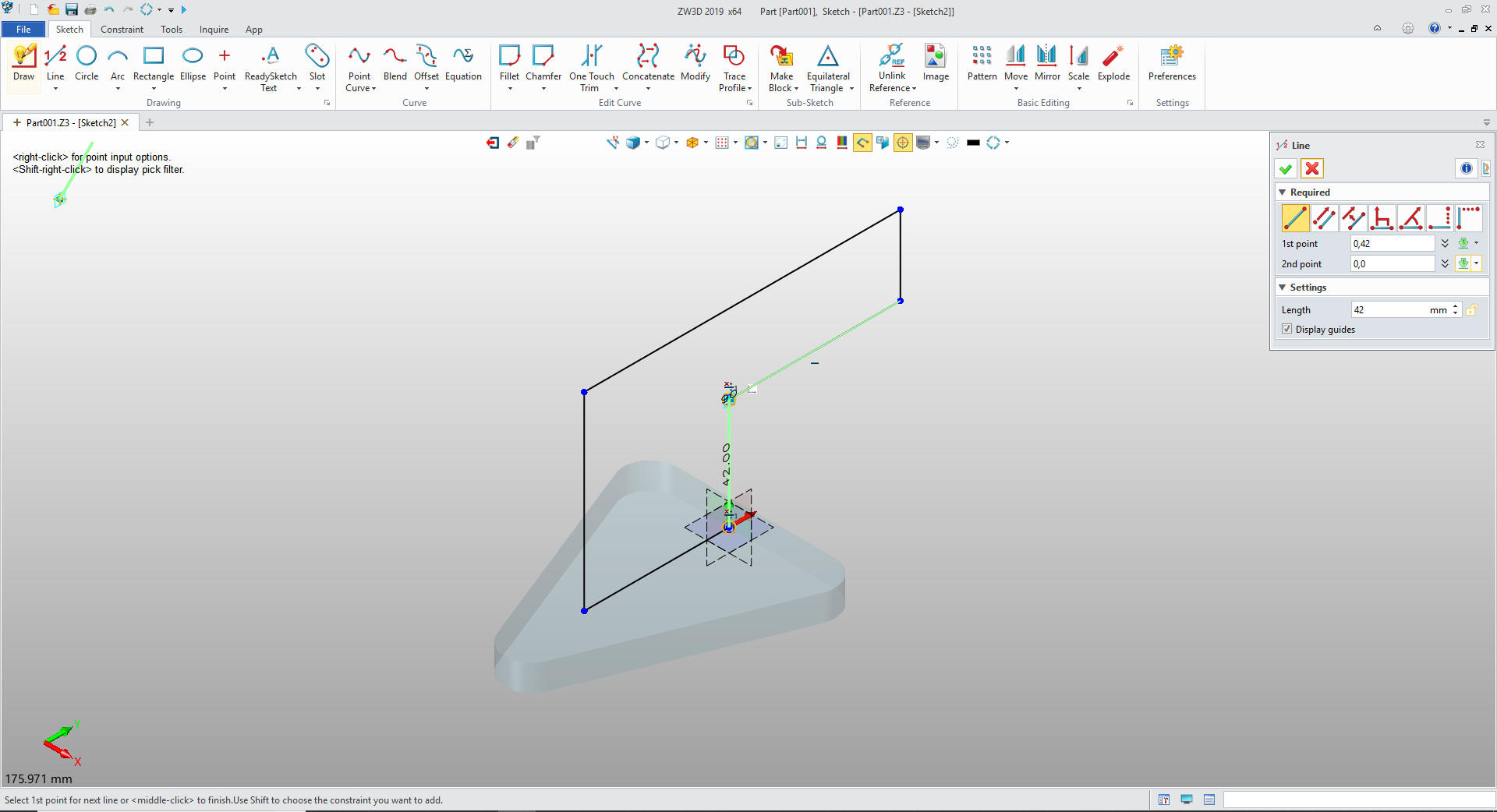
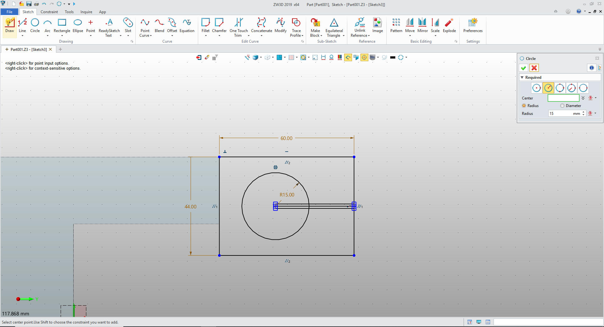
We create the right feature in one sketch. Again notice I am not
constraining any of the features. The two dimension were generated
by my creating a rectangle 60mm x 44mm
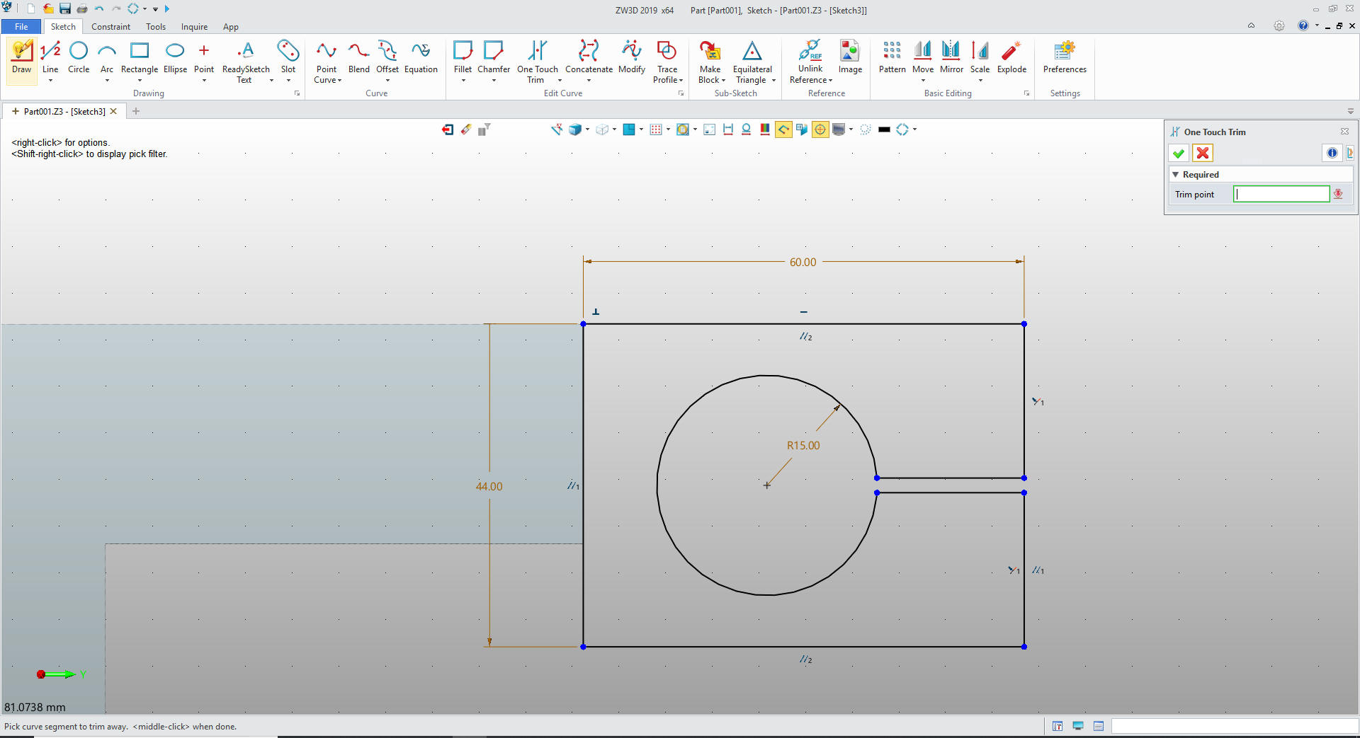
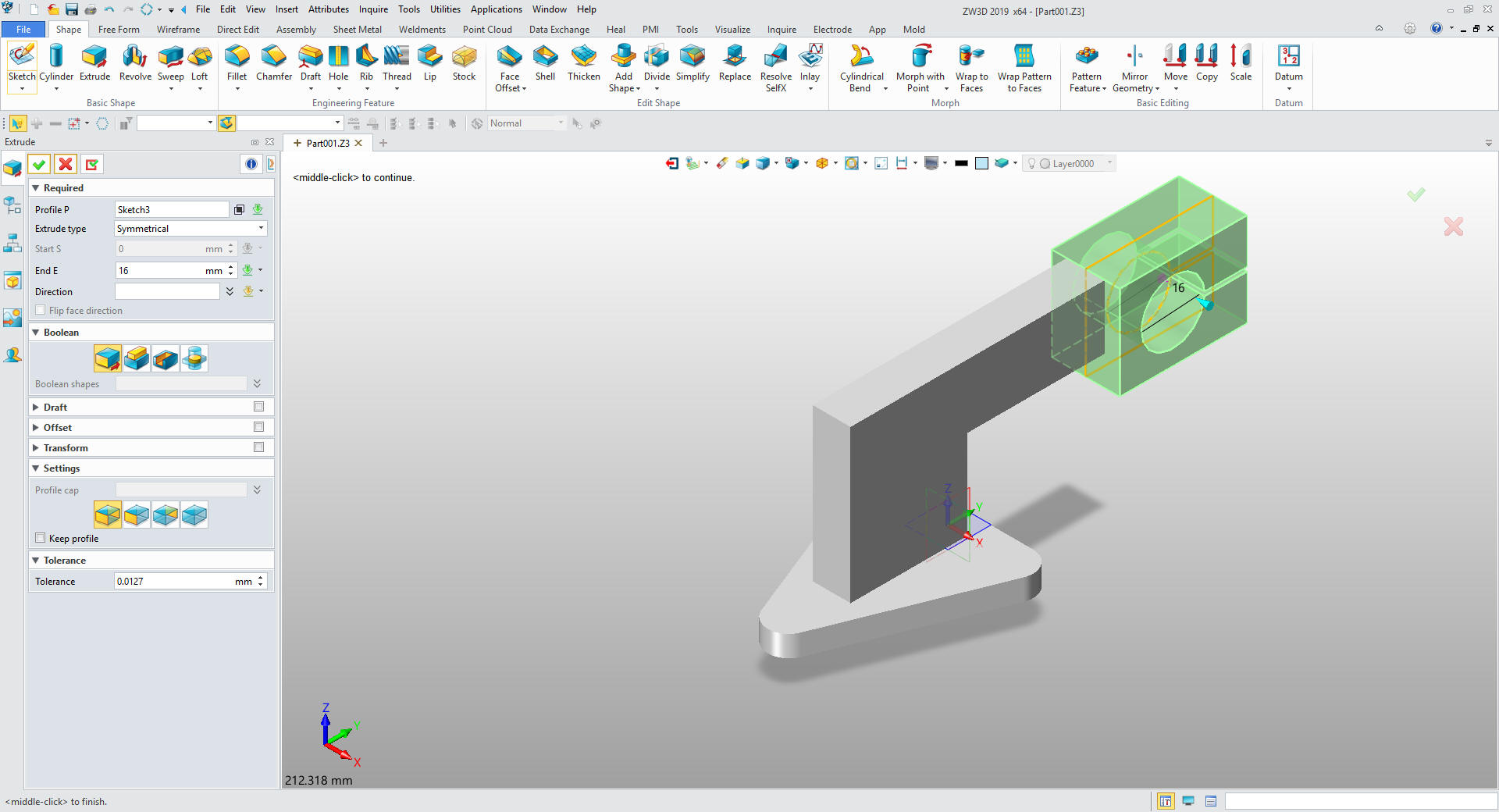
We trim the entities and we are done with our sketch.
Extrude the sketch 32mm symmetrical.
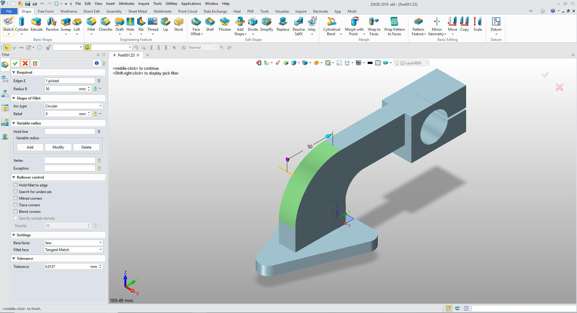
We
create the 20mm and 50mm fillets
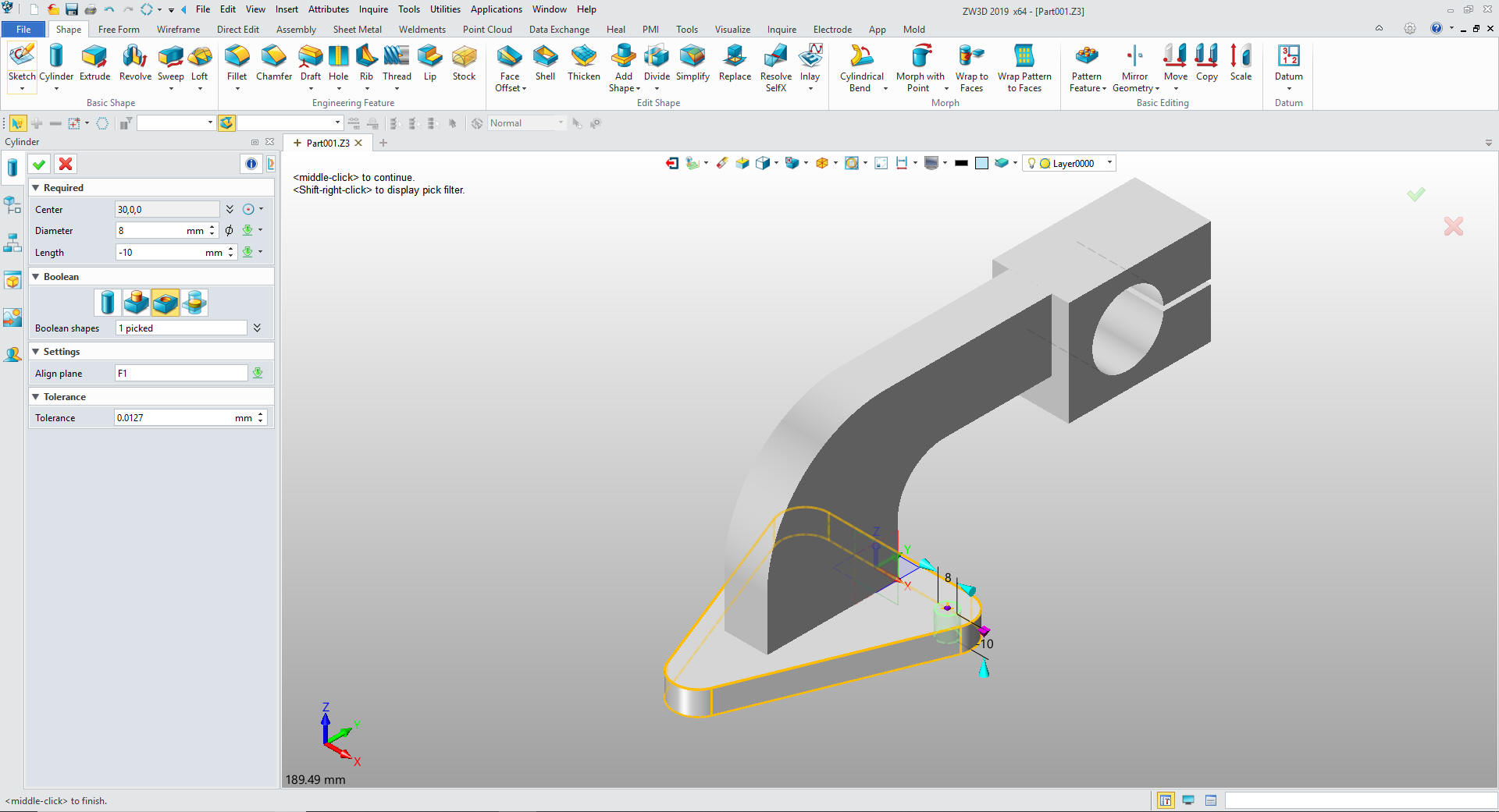
I know I told you I was going to sketch this part but I cannot
bring myself to sketch a hole. In ZW3D we have custom hole functions
but I am going to use primitive cylinders. We insert the primitive
cylinders and set them to remove and use the center of the arcs to
locate.
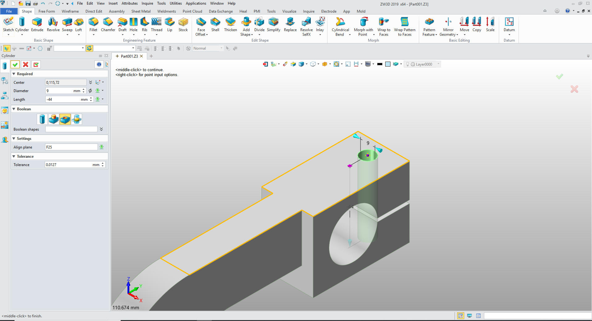
We
insert a primitive cylinder set it to remove size and locate it in
one command.
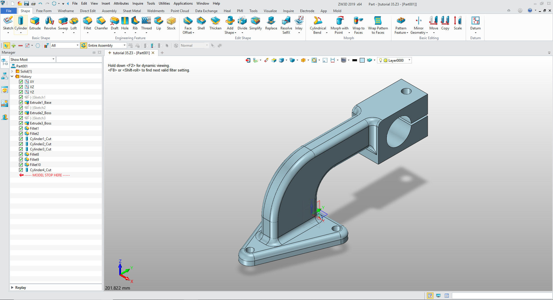
Now
for the most time consuming step the fillets and we are done. You
can see this part is very simple requiring just three sketches.
Give me a call if you have any
questions. I can set up a skype or go to meeting to show this part
or answer any of your questions on the operation of ZW3D. It
truly is the Ultimate CAD/CAM System.
If you are interested in adding professional
hybrid modeling capabilities or looking for a new solution to
increase your productivity, take some time to download a fully
functional 30 day evaluation and play with these packages. Feel free
to give me a call if you have any questions or would like an on-line
presentation.