|
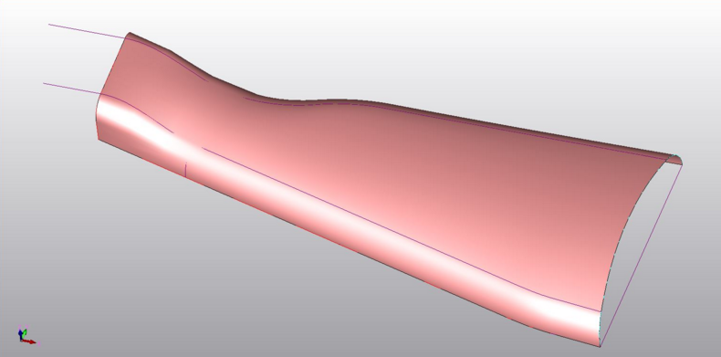
Below is an example
of surfaces working with scanned data. This
gives you an idea how surfacing works with
wireframe based entities used to construct the surface.
CADKEY was now creating the building blocks to become
the best Hybrid 3D CAD modelers.
Reverse Engineering 2015
-
AK-47 Project
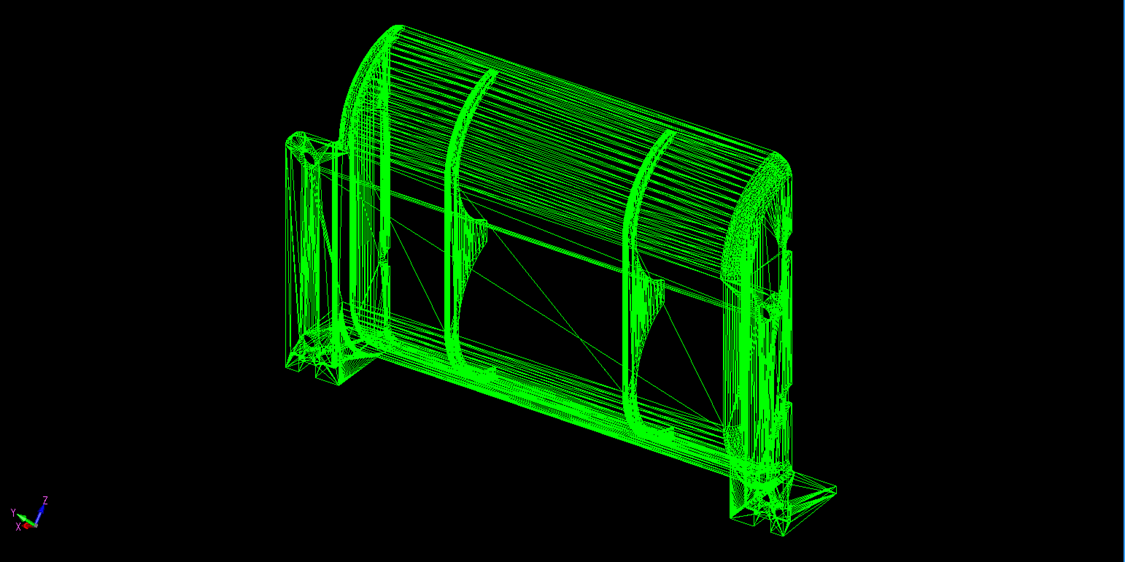
Below is an example of
a .stl.
This was created from a solid but in
the mid 1990’s we would use net surfaced
parts. We surfaced from 1989 until 1995, it
was labor intensive and incredibly tedious. This is sent to the sterolithography
machine to create prototype parts. Which of
course is now mostly done by popular 3D printers.
The only other
programs that offered 3D CAD were the high
end programs. They ran on expensive
workstations and were out of the reach of
many companies. In the beginning of the
1990’s all of these packages were still 3D
wireframe. Boeing had 1200 seats of CADKEY.
I was selling every Boeing supplier CADKEY
and expanding 3D CAD use throughout the
Northwest. I now realize that Boeing was
oblivious to the service I was providing by
making Boeing IGES, then STEP files
available to their suppliers
CADKEY or Catia? Boeing’s Billion-Dollar 3D CAD Mistake!
 We
do not want to forget Rhino. This was a PC
based surfacing only package. Later they did
add some Boolean solid modeling. It was a
very good and cost effective solution for
those that needed flexible surfacing. We
do not want to forget Rhino. This was a PC
based surfacing only package. Later they did
add some Boolean solid modeling. It was a
very good and cost effective solution for
those that needed flexible surfacing.
It was very
Autocadish and that instantly put me off.
But I decided to become a dealer due to its
popularity.
We took a one week
class. It was step by step and most of us
got lost by the second day. Most of the
focus was on organic shapes. The first
training project was designing a duck by
pushing and pulling on faces. They never did
get into mechanical design and most in the
class were mechanical designers, drafters
and engineers. I found it less useful than
the mechanically superior CADKEY with FastSurf so I dropped the product.
The high end programs
were years behind CADKEY in functionality.
Remember they were networked and ran on expensive
IBM workstations. They didn’t have a concern
about interoperability. We were reading IGES
files from all of large system like Pro/E
and Catia. There were some other systems out
that but they were not used in the
Northwest. Autocad was not even in the
picture. All of the large companies bypassed
the electronic drawing phase moving directly
to 3D CAD. Yes, they were generating AID’s
and printing them. Boeing called the AID the
"flat file" as compared to the 3D model.
The sheet
metal shops were some of the first to
require 3D models. It was funny that the
sheet metal shops lead the way. They could
actually turn properly modeled 3D wireframe sheet metal design
into flat patterns automatically using
software developed by the stamping machine
manufacturers. Now, of course, these parts had
to be designed correctly. You can imagine how
much cheaper it was to do a one button
unfold from a 3D model as compared to
developing the flat pattern from drawings.
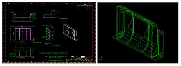
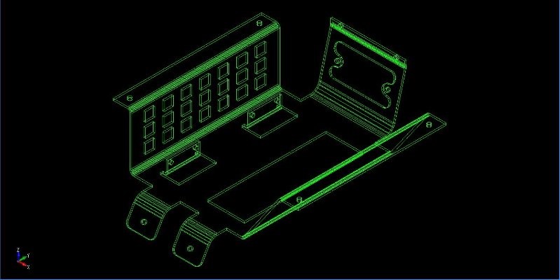
This is what a common
wireframe sheet metal part would look like
in CADKEY. Are you looking up or down
at the part?
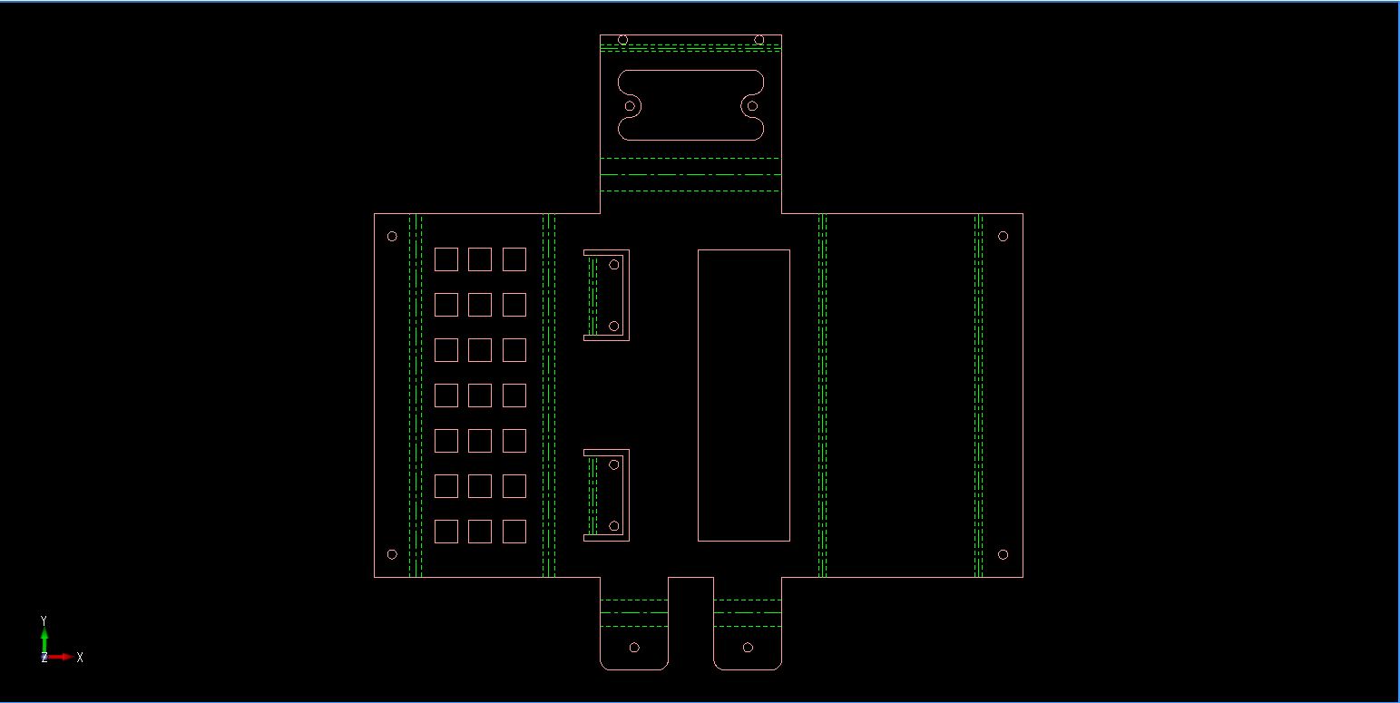
Here is the resulting
flat pattern
So the die was being
cast and CADKEY was benefiting.
It was
soon to become a 3D CAD/CAM world.
Manufacturing was
beginning to drive
the use of 3D CAD. They soon were demanding
the 3D model along with the AID or flat
file. The cost of machining started
dropping.
CADKEY was being
enhanced by leaps and bounds. Creating the
documentation was incredible. You could have
fully details AIDs (drawings) in hours.
The days
of creating a scratch drawing was quickly
fading.
CADKEY was unique, you
could have all of the parts, assemblies and
AIDs (drawings) in one file. We would design complete
projects in one file and have all of the
AIDs (drawings) included.
Yes, we were still
communicating with the AID (drawings) being printed
on paper. There were no PDF’s. The
supplier would get the model as an IGES file
with the AID as a print. Actually we could
translate the electronic drawings with IGES and DXF.
DXF has been a faux drawing translator until this day.
IGES was even worse. DXF and IGES would have
dimensions and sometimes views all over the
place.
But it was
not perfect and we could not standardize on
them. But the 2D graphics were relatively
stable and could be used by CADKEY to help
create 3D models and provide flat patterns.
Lost In Translation?
A Guide to 3D CAD Translation Formats.
But something amazing
was about to happen!!

The 1990's The Age of Solids
Surfacing is a very
tedious way of design. It was a horribly
time consuming way of creating parts that
could be converted to .stl or provide
machinable faces for CNC. That was all about
to come to an end. Even though there is a
bit of Surface design today in surface
sculpting, it is now mostly to
enhance our Solid modeling.
We started to hear about
Pro/Engineer. But it was a very expensive
and complex program and ran on a UNIX workstation. Boeing was deep into Catia. We heard about the high end systems
like Computervision and Catia dabbling in
solid modeling. But it seemed like it happened
all at once for the industry in 1995
with the introduction of the Parasolid (.x_t)
and ACIS (.sat) solid
modeling kernels.
FastSolid was based
on ACIS. It was a
Boolean system which is what we call direct
edit today. No history and you designed like
you do today with extrusions, spins, sweeps
and lofts. Then you would union, subtract or
intersect the solids to create your parts.
You designed on separate levels to create a bit of
history. When you did something you never
wanted to do again you would copy it to
another level. It was easy and fast. Miles
above history in productivity.
All of my CADKEY
customers were calling ordering the beta of
FastSolid. Soon all of my customers were
designing in solid models. It seemed like
Catia 4 came out at that time also using
solid models. Sadly, there was no way to get
solid model out of Boeing at the time and we
were still using IGES exporting wireframe
and surfaces.
CAM and CNC started
booming. There were many new CNC programs
such as SmartCAM, MasterCAM, SURFCAM, etc.
But we were translating in IGES.
Soon IGES released a
solid model translation code. It was used
for a short time. But there was a new
translator on the block. STEP. It translated
wireframe, surfaces and solids. This became
the standard export for the high end
systems, which at the time were Pro/E and Catia 4.
CADKEY and FastSolid could read them all. It
was the standard hybrid 3D PC Based CAD
tool. At least in the Northwest.
Soon these two
new solid modeling kernel gaining
popularity.

ACIS and Parasolids.
Soon many companies
were licensing the above packages and
creating PC based 3D solid modeling package.
We had Fastsolid,
Trispectives, TurboCAD, CorelCAD and a
variety of programs using the ACIS module.
All were attempting
to be mechanical design packages. And some
were surprisingly good. I really enjoyed
CorelCAD. But they did not get the support
and faded away. They were very inexpensive
costing hundreds not thousands.
AutoCAD set the price
for a CAD company to be viable. That is why
we all pay around $4,000.00 per seat for the
intermediate CAD systems.
But Trispectives, a
solid modeling graphic design package caught
my eye. I started playing with it and it had
drag and drop shapes from catalogs design concept, but it was no
mechanical package with no documentation
functionality. But it had realistic
rendering and easy to use animation.
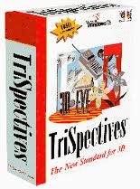 Trispectives
being ACIS could export and import the
common .sat file. Fastsolid also being ACIS
allowed us to move parts and assemblies back
and forth. I quickly became a dealer. The
price? $495.00 Trispectives
being ACIS could export and import the
common .sat file. Fastsolid also being ACIS
allowed us to move parts and assemblies back
and forth. I quickly became a dealer. The
price? $495.00
We had a huge CADKEY
user base in the Northwest that totaled over
750 on maintenance and another 1000 not on
maintenance (Boeing had an additional 1200). We
would have huge seminars and user group meetings ever month.
There was one meeting
where a couple of my customers gave a
presentation of the mixture of CADKEY,
Fastsolids and Trispectives. We had
incredible graphics. Transparent views,
graphic labels, sectioned realistic views.
Etc. It would rival any of the products
today. We were selling CADKEY, FastSolid and
Trispectives hand over fist. These were very
simple packages to use. My company was just
me and my bookkeeper/computer tech. Yes, we
had to be very PC savvy. We did it all from
computer supply to computer networking. No,
windows did not come with networking.
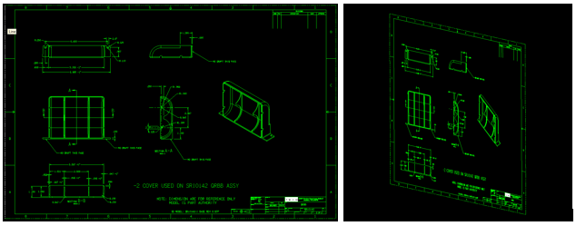
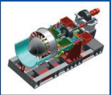
Here is one of the
images from the above presentation, circa
1997.
That went on
throughout the 1990’s.
As I think back it
is quite surprising how everything just fell
into place!
CONCEPTUAL DESIGN Which 3D CAD Paradigm is Best?
But the late 1990’s
were to lead the way to the PC being the
Standard 3D
CAD/CAM computer platform!
There were a few PC
based solid modeling products that showed up
but never really made it.
Think3, Solid Edge,
Vellum, CoCreate and a few others.
All of the high
end 3D CAD systems were moving to the PC,
Pro/e, Catia 5 and UG.
They came
down in price to around $12,000.00. But the
base price did not reflect the complexity of
the products. It was not an easy sale they
would add module on top of module. By the
time you were done you were into the tens of
thousands.
Autocad was still struggling with 3D
CAD. Nothing was coming out of Autodesk.
They still were the King of the Electronic
Drawing Package. Architectural, Civil, HVAC
and the Industrial/Mechanical industries
that had not moved to 3D were using this
popular electronic drawing package. Autocad
was becoming somewhat of a cult. I would
show a manufacturing company the benefits of
3D CAD and they would seem to be scared to
make the move or they were not paying for
Autocad!
Enter IronCAD
 Trispectives
was sold to a company that OEM CoCreate.
They started turning Trispectives into
IronCAD. Since I was a Trispectives
dealer, I was somewhat involve in the
development. When it was released it was
miles above any package at that time. It had
integrated history and direct edit modeling
(Probably the influence of CoCreate). The
integrated direct edit functionality made
making changes easy, even on imported parts. They
added an AID (drawing) module. It still had its
incredibly powerful realistic rendering and
animation. This made IronCAD the most advanced
and productive conceptual 3D CAD package ever created. And
do you know what? It still is. Trispectives
was sold to a company that OEM CoCreate.
They started turning Trispectives into
IronCAD. Since I was a Trispectives
dealer, I was somewhat involve in the
development. When it was released it was
miles above any package at that time. It had
integrated history and direct edit modeling
(Probably the influence of CoCreate). The
integrated direct edit functionality made
making changes easy, even on imported parts. They
added an AID (drawing) module. It still had its
incredibly powerful realistic rendering and
animation. This made IronCAD the most advanced
and productive conceptual 3D CAD package ever created. And
do you know what? It still is.
An interesting note, CoCreate was purchased
by PTC and released as Creo Direct.
But there was
another PC based 3D CAD package that was being introduced.
Solidworks.
 Many
say Solidworks was some huge innovation, but
it really was a poorly designed cheap knock
off of Pro/E for the PC. Luckily it came out
a couple of years before Pro/E moved to the
PC. I was the biggest 3D CAD VAR with both
CADKEY (which was purchased by Bob Bean at Baystate) and Trispectives. CADKEY bought
both FastSurf and FastSolids from Robert
White and was now the best and only hybrid CAD system
available on the PC. Many
say Solidworks was some huge innovation, but
it really was a poorly designed cheap knock
off of Pro/E for the PC. Luckily it came out
a couple of years before Pro/E moved to the
PC. I was the biggest 3D CAD VAR with both
CADKEY (which was purchased by Bob Bean at Baystate) and Trispectives. CADKEY bought
both FastSurf and FastSolids from Robert
White and was now the best and only hybrid CAD system
available on the PC.
The Solidworks VAR
representative came to me and offered me a dealership. I
laughed and said “who would buy this piece of
crap”. How was I to know that Dassault would
pay over 300 million for it. I still think
they bought it to help develop Catia 5 (I
will get to that later). (I did start
selling SW though an agreement they had with Surfcam in 2001)
It was very
interesting Solidworks and IronCAD were both
available and competitors. I had many
opinion leaders looking at both packages and
making a comparison.
But one of the worst
things in my career happened. Both
Solidworks and IronCAD had a serial number
and password. Things were great. The
software, like Autocad in the past was being
passed around by CAD professionals. IronCAD was
getting rave reviews. It looked like it was
going to be the winner.
IronCAD corporate got
wind of serial numbers and passwords being
published on the “new internet”. It was the
same with Solidworks. But they said this
cannot be, and against my wishes quickly put
strict copy protection on IronCAD. Virtually
all interest in IronCAD stopped.
Solidworks continued
to use the
easily copied serial number and password
until 2007 virtually guaranteeing them the
top 3D CAD PC based program position. Sadly CADKEY put on
strict licensing and after years of being
the most popular 3D CAD package they too, had
their sales slowed to a trickle.
The Two CAD Programs that Set the Path to 3D MCAD Chaos!
It was funny many of
the CADKEY VARS became Solidworks VARs, Bob
Bean, Baystate Technology President, who had
just purchased CADKEY got angry and
cancelled their dealerships basically
tossing CADKEY on the trash heap of lost CAD
programs. We will get into the downfall of
CADKEY in the 2000s article.
The 2000's - The Age of 3D CAD Un-Enlightenment!
Update August 9,
2017
I was reading
Ralph Grabowski's (Probably one of the few
fellows that have been involved the CAD
world as long as I have) latest email where
he said that Autodesk was also bidding for
Solidworks. This was the first time I heard
of this. Now we can understand why Dassault
would pay 300+ million for a non-proven
mediocre PC based Pro/e clone. Remember
Boeing was clambering for a parametric
history based system.
But CADKEY did something quite incredible.
ENTER CADKEY PARAMETRICS
The writing was on
the wall. History based design was here and
engineering liked it. CADKEY seeing this
created what they called CADKEY Parametrics.
They added parametric history based design on top of a
wireframe, surfacing and direct
edit program. Quite the opposite of what is
happening today. It was truly incredible and
quite functional even in the beta release.
I remember a
presentation we did at Boeing. We did it all
wireframe, surfacing, direct edit solids and
finished off with parametric history based design. It
was by far the best presentation of CAD I
had ever seen and it was done with basically
beta software. The Boeing folks left
drooling.
I started selling
what was now fondly called “The Parametric
Module”. We had quite a few CADKEY users
from Boeing stepping up to the line for
training. “History Based” design was the
Buzz word and it was on everyone’s lips.
CADKEY was
on its way to be the most innovative,
flexible hybrid modeler of the day. It was
destine to lead the 3D CAD industry to a new
level of productivity. I was the only dealer
in the Northwest, I was already counting my
money!!
Introduction of Catia 5 into Boeing
 Now,
since I had virtually all the Boeing supplier
CAD business tied up using CADKEY, let me tell you what
happened with the introduction of Catia 5. Now,
since I had virtually all the Boeing supplier
CAD business tied up using CADKEY, let me tell you what
happened with the introduction of Catia 5.
I remember calling a
Boeing group trying to expand CADKEY in
Boeing. He asked me “Does it have history
based design?” I said “you do not want
history it is very complex and difficult to
use as compared to Boolean design” (Catia
4). He said “We have to have History”. I
thought oh no, they are being introduced to
Pro/e.
But I soon found out
that Catia 5 was coming out. Oh yes, Boeing
had developed a case of "Pro/E" or history based
CAD envy. I am sure that Catia 5 was
directly influenced by Boeing wanting
history based design. I am sure they went to
Dassault and said we are thinking of moving
to Pro/E causing the birth of Catia 5. Pro/E,
no matter how complex offered the ability to
handle large models. And an Airplane is a
large assembly. Of course, Dassault now had
the Solidworks technology and a staff which
included the knowledge of a very experienced
former PTC design team.
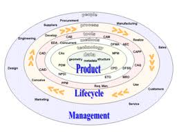
Enter PLM (Produce
Lifecycle Management and MBE (Model Based
Enterprise).
PLM & PDM Defined
 With
Catia 4 Boeing was delivering the STEP model
with paper
prints . This was a great expense and time
consuming. Even though the AID (drawing) was in a
native Catia 4 file the only way to view it
was a print. I ask myself, was this the
problem they were trying to solve with MBE
(Model Based Enterprise) and the introduction of
the PMI (Product Manufacturing Information)
format. What could only be called a 3D
drawing? With
Catia 4 Boeing was delivering the STEP model
with paper
prints . This was a great expense and time
consuming. Even though the AID (drawing) was in a
native Catia 4 file the only way to view it
was a print. I ask myself, was this the
problem they were trying to solve with MBE
(Model Based Enterprise) and the introduction of
the PMI (Product Manufacturing Information)
format. What could only be called a 3D
drawing?
Catia being a Pro/e clone had separate part,
assemblies and drawing files. I am sure the
PLM folks were having a hard time managing
the the separate files and keeping them
synchronized. They were also delivering
prints at the time. Interestingly, would
they have made the single file PMI if they
knew PDFs were around the corner?
It is quite bizarre the
PMI concept put the
dimensions on separate planes in the 3D
space. It requires
the native Catia 5 software, Enovia (an
expensive viewer) or a 3rd party
viewer. It is not a viable standard and
quite convoluted. They are trying to make it
a standard but it is going to be a failure.
Even today we do not have a standard “Free”
PMI importer and it has been 18 years!!!
Why MBE/MBD/PMI Will FAIL
Why MBE/MBD/PMI Will Fail Part II
PLM/MBE/PMI Absurdity!!
This article exposes
the unworkable complexity of the PMI.
PMI vs AID
(Associated Information Document)
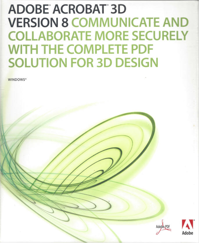 Adobe came out with
Acrobat Pro that actually could read the
native Catia 5 file and PMI. Then could
export the model as a STEP. I really don’t
know what happened with this. Adobe sold it
off. Maybe it interfered with the Enovia
sales or created a corrupt model from the
native Catia part. Adobe came out with
Acrobat Pro that actually could read the
native Catia 5 file and PMI. Then could
export the model as a STEP. I really don’t
know what happened with this. Adobe sold it
off. Maybe it interfered with the Enovia
sales or created a corrupt model from the
native Catia part.
Free PMI Importer?
Sadly PDF was right
around the corner. That would have kept the
process standard and simple. With the solid
model and AID as a PDF, you would have
had a very simple engineering deliverable.
Nothing had to change. Except there would be
no more paper.
Standard Cloud Based Engineering Document Control
Standard Cloud Based Engineering Document Control Part II
The Embedded Title Block! A PLM Solution!
But they were just
too far gone. PLM and MBD have cost Boeing
millions if not billions trying to
implement. The suppliers were lost. Today
Boeing demands that the supplier buys a
3rd party validation program to assure that the solid model
is the same as the solid model they are
machining. Apples to apples? Of course, but Catia 5 produces some of the most corrupt
part files in the industry. Boeing has also
created a Producibility Group to review the
release PMI!
Compare and Validation Programs? Band-Aids for Self Inflicted Wounds!
One of the
problems of moving from Catia 4 to Catia 5
was that the files could not utilized by
either system. The only thing they have in
common was the name.
Luckily
there was not a lot of use of Catia 5 since
all of the Airplanes were designed in CADKEY
and Catia 4. But that changed in the
beginning of the 2000’s. This change
has cost and is still costing Boeing and
Airbus billions in legacy data
incompatibility.
They could have
moved to many other CAD packages with much
more interoperablity. I sold them CADKEY and
tried to get them to buy IronCAD, both could
import and export Catia 4/5 native files. I
don't think Catia 5 still can read Catia 4
files directly. I suppose they did this to
force the use of Catia 5, but within the
company? Incredible!
IRONCAD/INOVATE = Catia 4.5
- The Catia incompatibility Solution
"I have worked with Boeing and Catia for
over 30 years. Dassault is responsible for
keeping Boeing one of the most ignorant and
isolated manufacturing companies. Their lack
of interoperability is beyond belief.
I will get into more
problems with PLM, MBD and Catia 5 in the
next decade.
The beginning years
of the millennium were full of new
innovation and problems as all 3D CAD moved
to the PC.
The 2000's were an
exciting time for TECH-NET. CADKEY was
getting ready to provide native translators
for Unigraphics, Pro/E, Solidworks, Inventor and Catia with their
CADKEY 20. We became Pro/E dealers. Then
took on Solid Edge. Direct edit became a
reality that could not be ignored with the entrance of SpaceClaim
and Siemens Synchronous Technology!!
And so much, much more.
The 2000's - The Age of 3D CAD Un-Enlightenment!
Please feel free to stop by our website
below for a variety of articles on the State
of our Industry, interesting articles on 3D
CAD Productivity and a few of our projects!

Viewpoints on Today's 3D CAD and
Engineering Industry
Here is a taste
of what is there. This is my favorite and
most popular article.
TECH-NET Engineering Services!
We sell and support IronCAD and ZW3D Products and
provide engineering services throughout the USA and Canada!
Why TECH-NET Sells IronCAD and ZW3D
If you are interested in adding professional hybrid modeling capabilities or looking for a new solution to increase your productivity, take some time to download a fully functional 30 day evaluation and play with these packages. Feel free to give me a call if you have any questions or would like an on-line presentation.
For more information or to download IronCAD or ZW3D
Joe Brouwer
206-842-0360
|