3D Modeling Techniques ZW3D vs 2 Solidworks Lesson
Eight Streamlined Sketching/Feature
Based Modeling Two Similar Parts and AIDs:
Single File
I saw some Fusion 360 exercises online and I decided to compare
IronCAD. It quickly turned into a study in modeling techniques. I have created
many comparisons to Fusion 360, Onshape, Solid Edge, NX, Creo,
Catia and Inventor
lessons to show the difference between
IronCAD and my modeling techniques. I found the presenters working
identically wasting massive amounts of time
with overly complex constrained sketching procedures. I was so unimpressed that
I decided to model the parts or assemblies showing my modeling techniques plus 's superb design system.
3D Modeling Techniques Defined
Many of these modeling techniques can easily be implemented even
within their existing system. I call it Streamlined Sketching and
Feature Based Modeling. Please review a few of the above ZW3D
comparison lessons, there are some very stark differences.
It really is tough
for me to sit through a constrained sketching lesson. I wonder if
PTC had any draftsman with any descriptive geometry skills when
developing this concept. There should have been an alternative
sketching process. I was trained in 3D CAD prior to the constrained
sketching and we basically did it like we did on the drafting board.
I am sure many of you have experienced non-constrained sketching
with Autocad.
You can see here how tortuous and time
consuming constrained sketching is.
While creating 3D models from drawing is the very best
way to learn 3D CAD and maybe some design techniques it does not
expose the designer to the design flexibility necessary in design.
ZW3D is all top down due to the multi-object model environment.
Creating mating parts is a cruise. But modeling is just one aspect of a
well designed productive 3D CAD system.
Solidworks
is a marginal 3D CAD system based on the dated Pro/e (Creo) history
based modeling system. I have sold this product years ago and found
it, like all of the other Solidworks clones, not productive enough
for our engineering department. We use what we sell. That gives us
the experience to effectively support our user base.
I would do a
video, but I really am not good at it. So I will show you step by
step. I will try and get ZW3D support to create one. They are
very good.
The modeling technique is hugely responsible for
the level of productivity. Those of you that are only trained in the
constrained sketching world are truly limited by not
using the freedom of feature based design, that is available in even
the most Solidworks-ish of CAD systems. If your
designers are designing in these very unproductive and time
consuming processes it might be time to review your standard design
processes. Don't have any do you?
These lessons have actually turned into exercises in
modeling techniques as compared to showing a more productive CAD
systems. Again, I say, there are many different ways to model a part.
I see with my exposure to direct edit modelers like CADKEY, I
rarely sketch like you see the Solidworks fellow doing. I have always
created my basic sketches by mostly creating offsets and extending
and trimming or. It seems to be much easier. I never put in a fillet that
can be created later. What do you think?
Let's get started!
You will see
with Streamlined Sketching and Feature Based modeling is much more
productive and flexible. It gives you a more real world feel to
your design process and is a much more pleasurable and productive experience.
Modeling Technique Note:
There are two similar parts. In
IronCAD we have a single model environment, ZW3D offers a
Multi-Object environment. As I started these parts I realized I
would have two parts to define. So I will start with an assembly
that include the two parts. I am wondering it this would also be a
viable solution for the Solidworks clones, unless they are already
doing it.
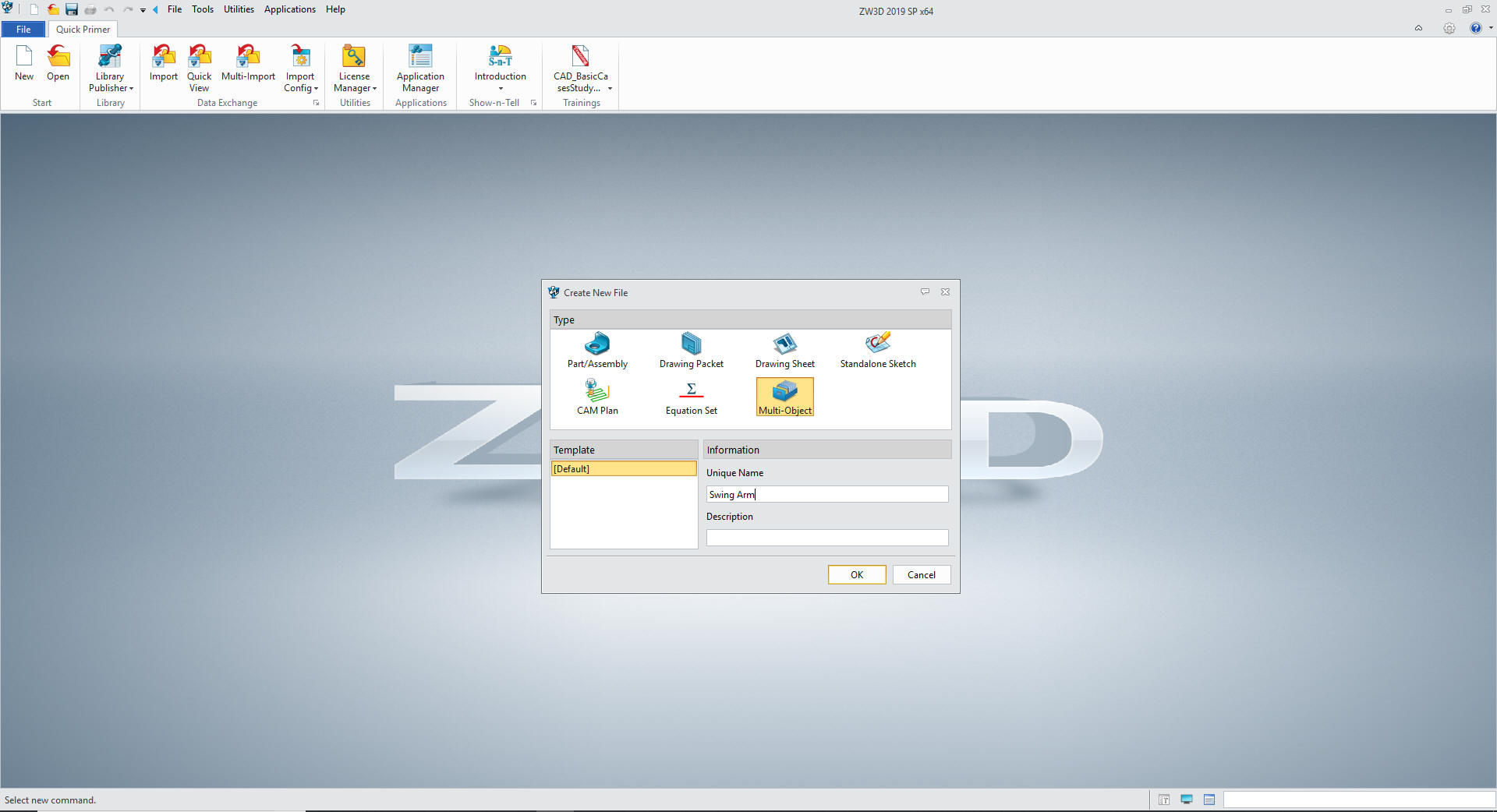
So we open an new file by selecting a Multi-Object
file type and name it Swing Arm.
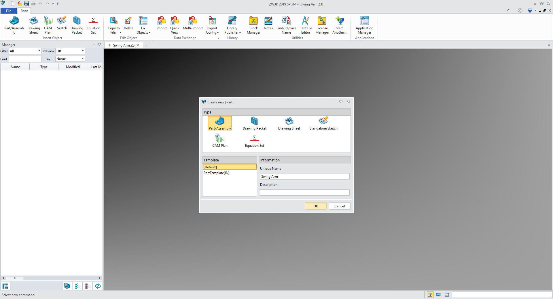
We
will open a part and name it Swing Arm. This will serve the purpose
as the top file.
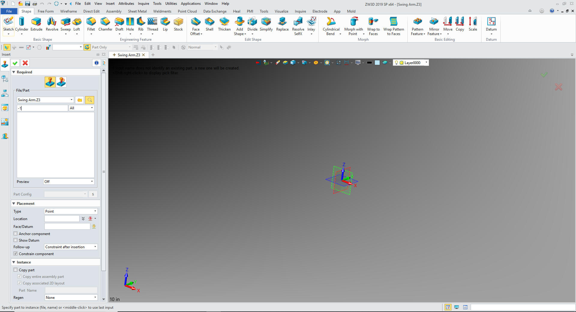
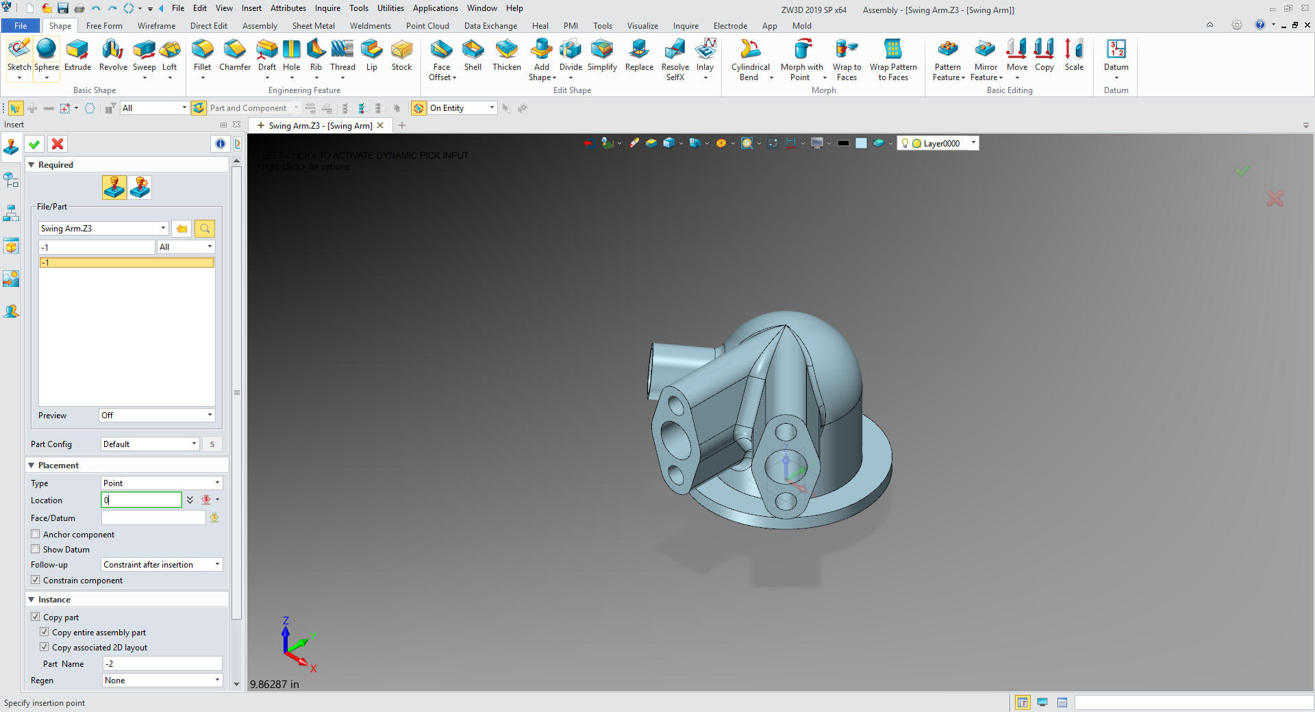
Under
Swing Arm we will insert a component -1
We can
now start creating -1. We will insert -2 later when we are done with
-1
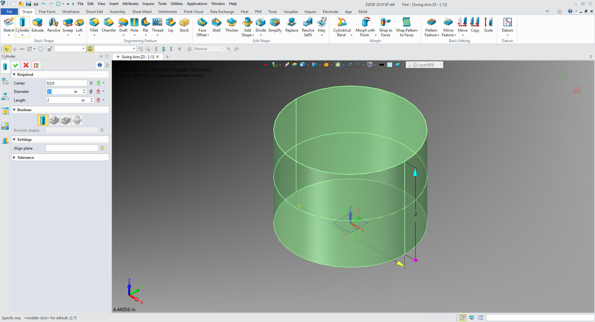
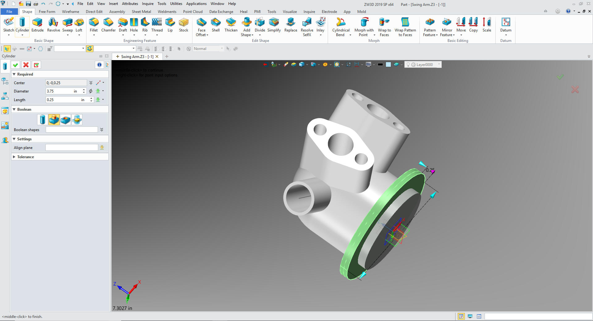
We insert a primitive cylinder and size it.
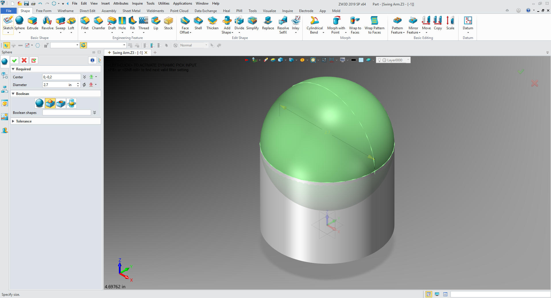
We
insert a primitive sphere at the center of the top face of the
cylinder, set it to add and size it.
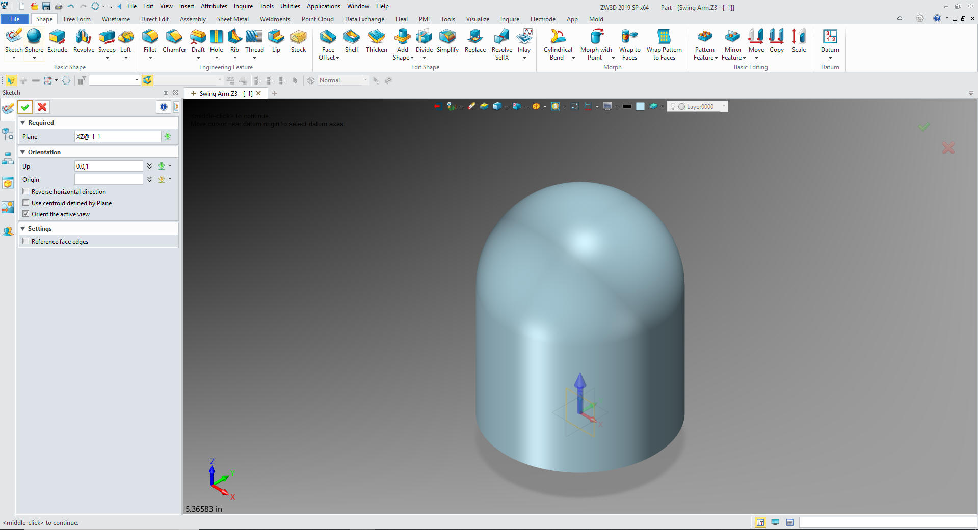
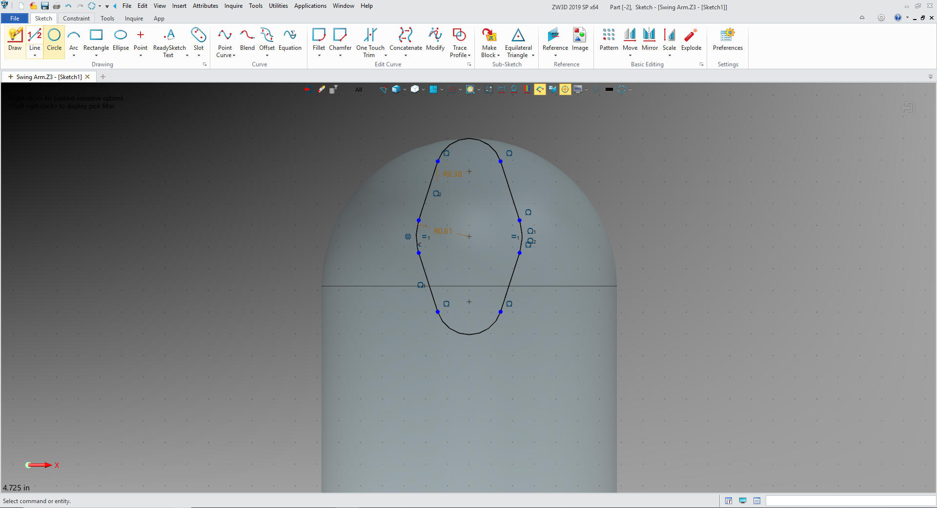
We
create a sketch on the XZ plane
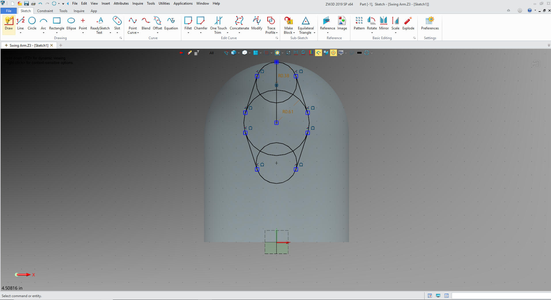
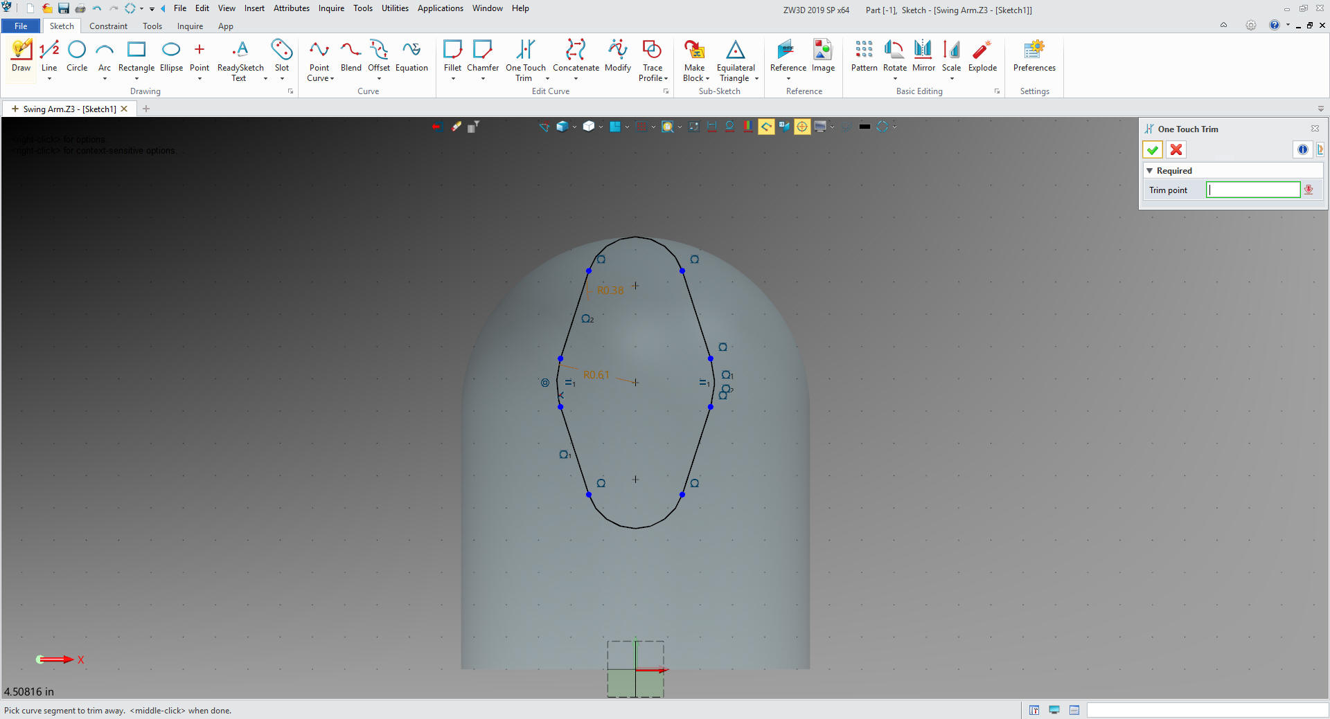
We create our
first boss. We use a reference line to locate the centers of the
circles and add the tangent lines. No constrained sketching. I call
this streamline sketching.
We trim or
delete the entities and we are done with our sketch.
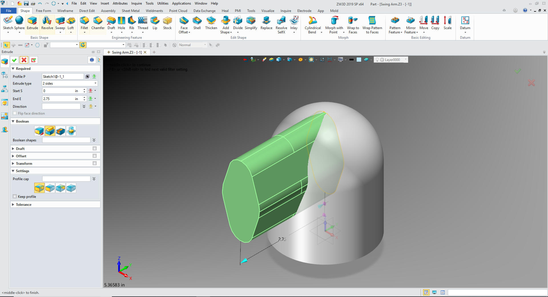
We extrude the profile to 2.75 and set it
to add.
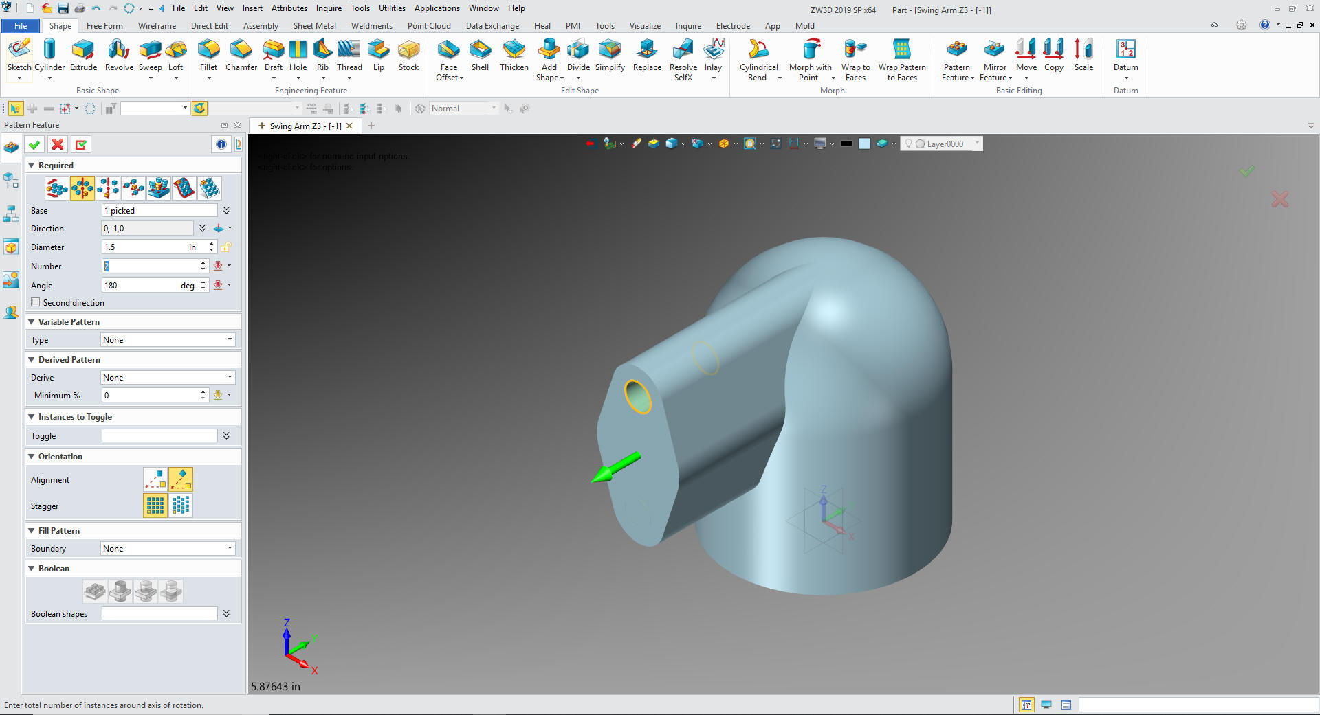
We inserts primitive cylinder at the
top center circle set to remove and size it. We use the pattern
feature and rotate the top hole 180 degrees.
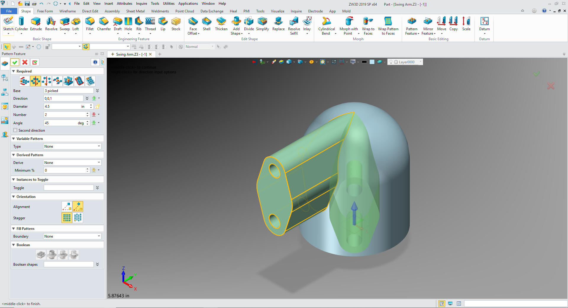
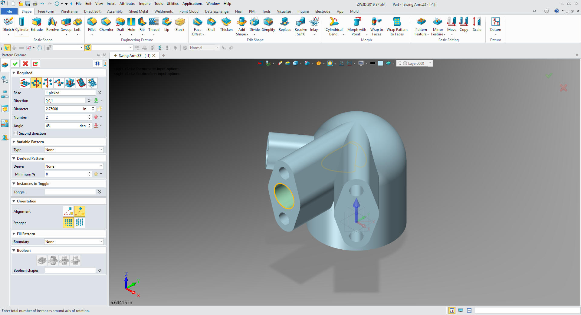
We
take those features and pattern them by rotating 45 degrees.
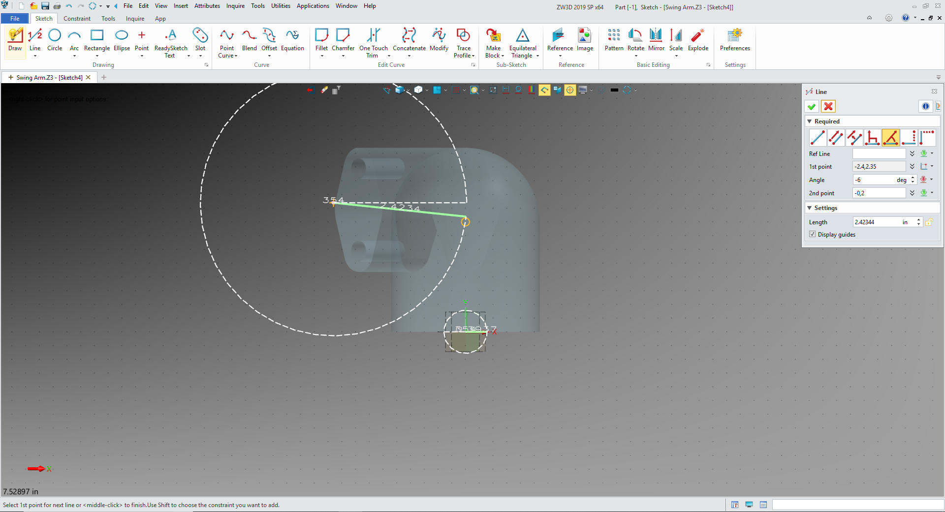
We
create a plane at 45 degrees to set up the other boss and create a
sketch. We create a line offset -2.4 X 2.35 and set the angle and
length to the center of the cylinder.
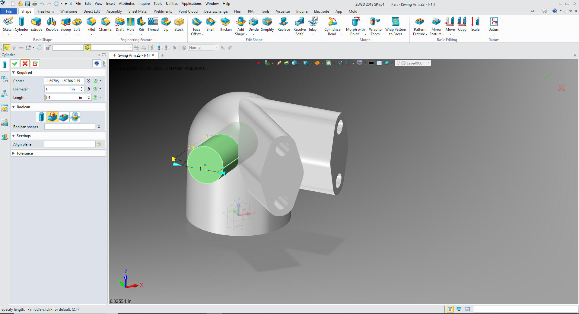
We
insert a primitive cylinder at the end of the line we just created
and it automatically set the cylinder parallel we set it to add and
size it. How easy!
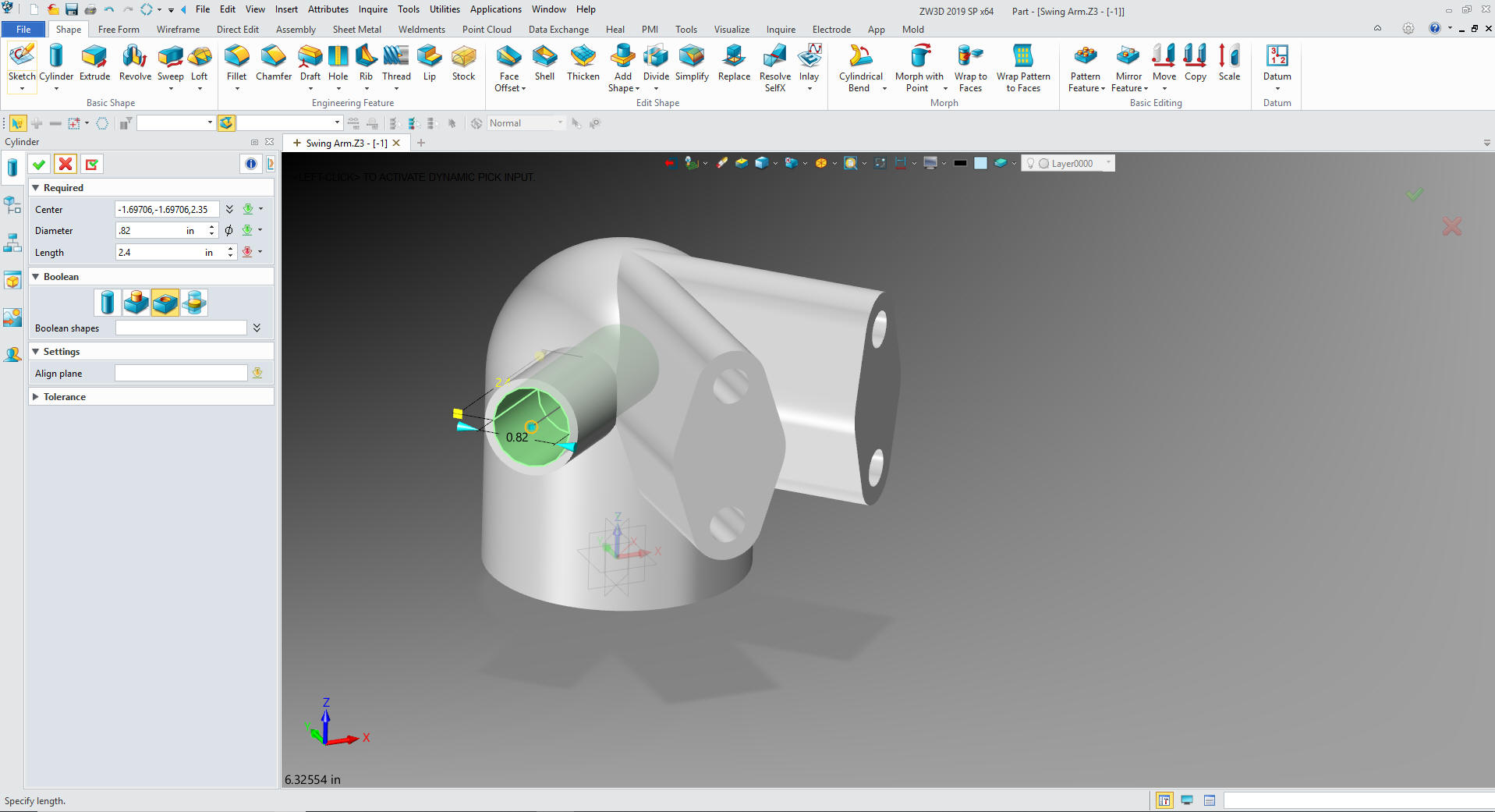
Now
for the hole, just insert another cylinder using the center of the
boss, set to remove and size it.
We
now insert the main boss hole and pattern it.
The Solidworks
presenter misses this step and has to use direct edit to remove
extraneous graphics later. ZW3D has robust direct editing but it
should be used as a last resort not just for convenience. It is poor
design practice.
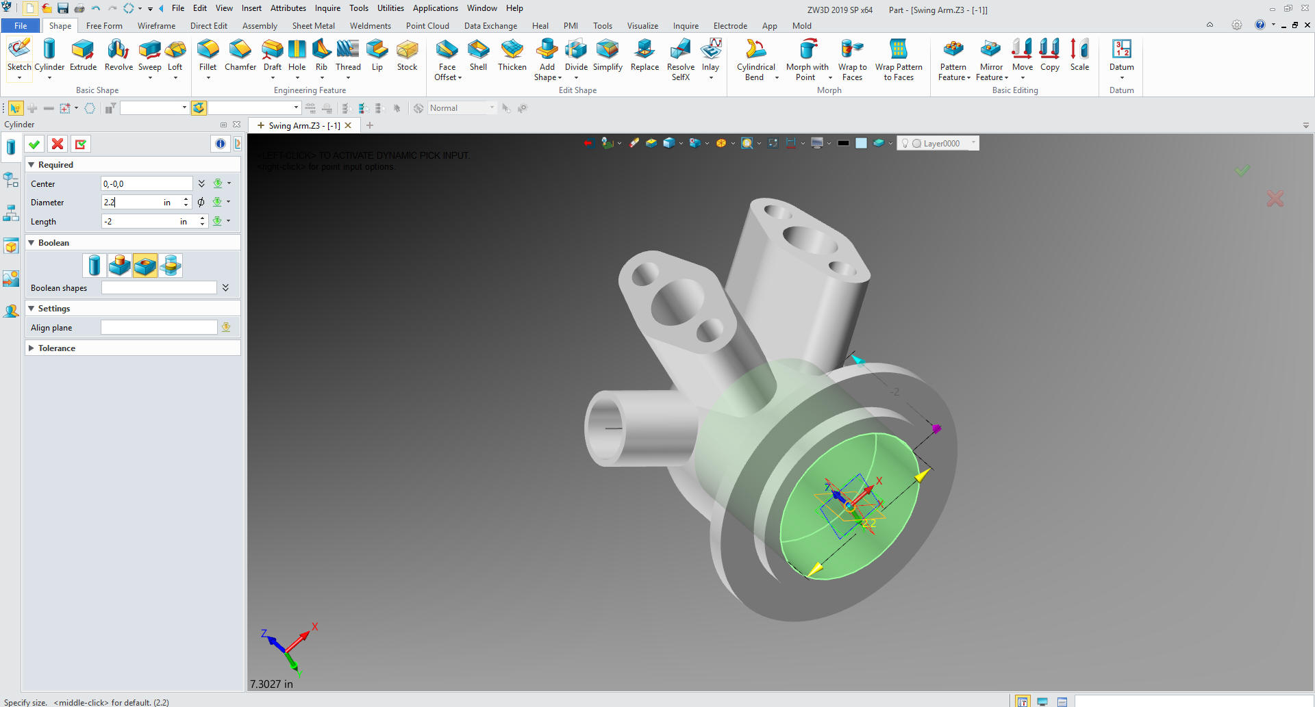
Now
for the bottom ring. Again we insert a primitive cylinder on the
center of the bottom of the main cylinder and set it to add, locate
it and size it.
Now
just insert another cylinder at the center of the bottom of the main
cylinder and set to remove and size it.
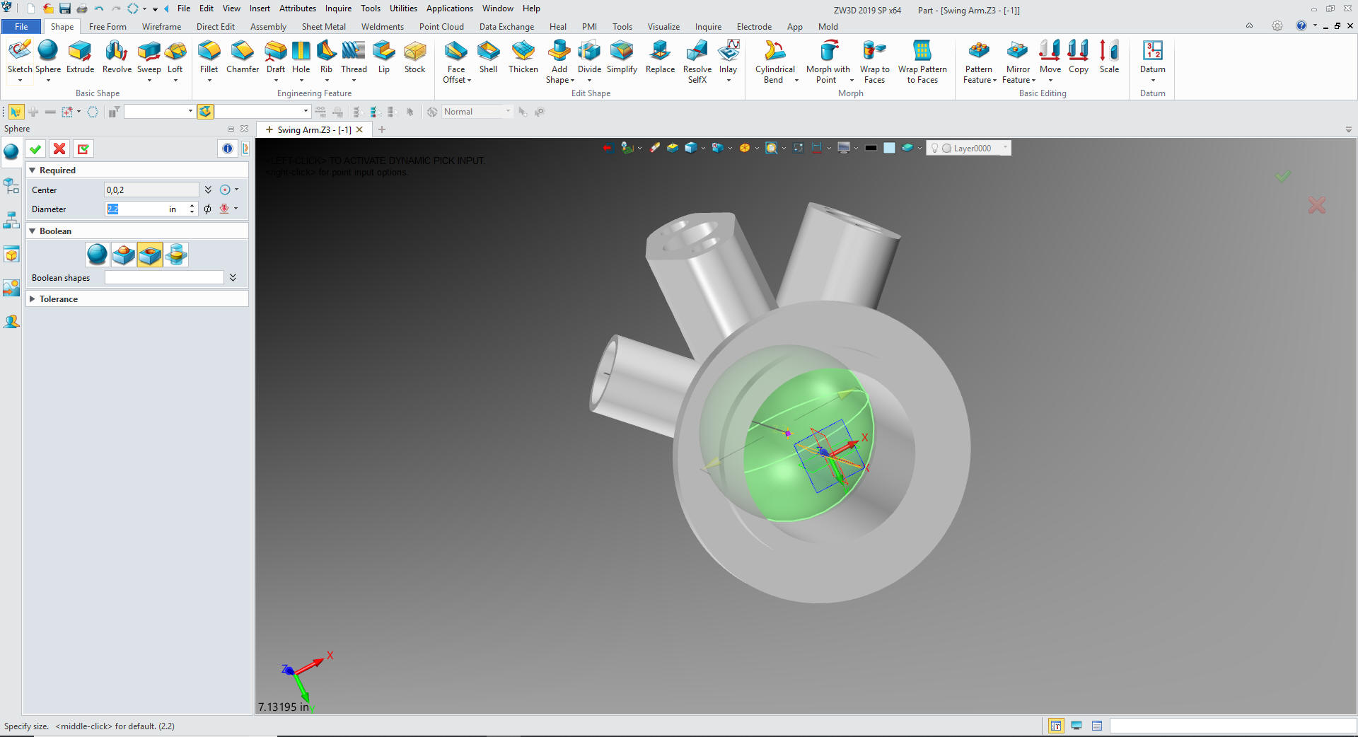
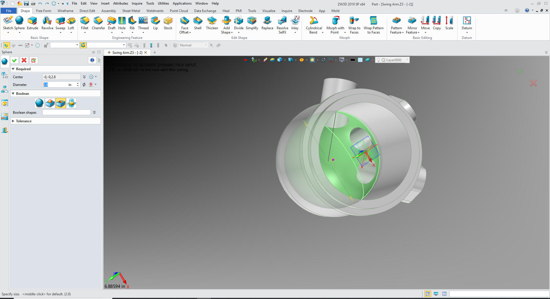
We insert a primitive sphere at the center of the new feature set it
to remove and size it.
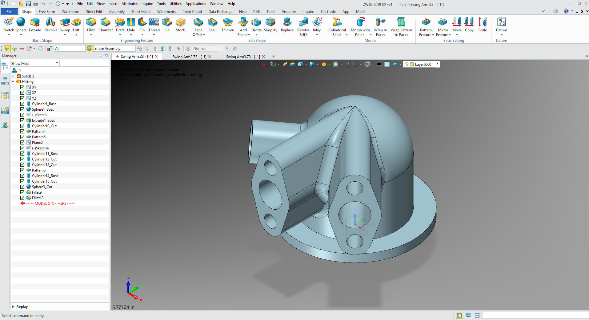
We are done with the part now we just add the radii.
Now
for -2. We will insert a new component. We will take the -1 copy it
and name it -2 and locate it to X0Y0Z0
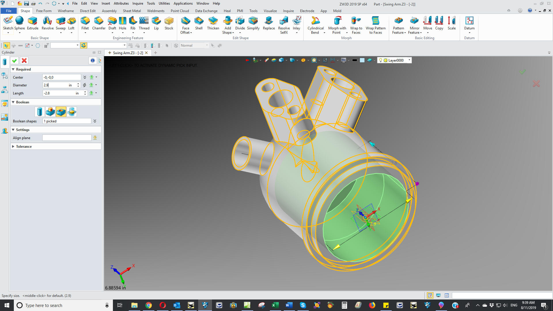
We
open -2 and delete the fillets and edit the main cylinder.
Then the sphere
We
got to the main boss sketch and relocate.
That
moves the bosses into place
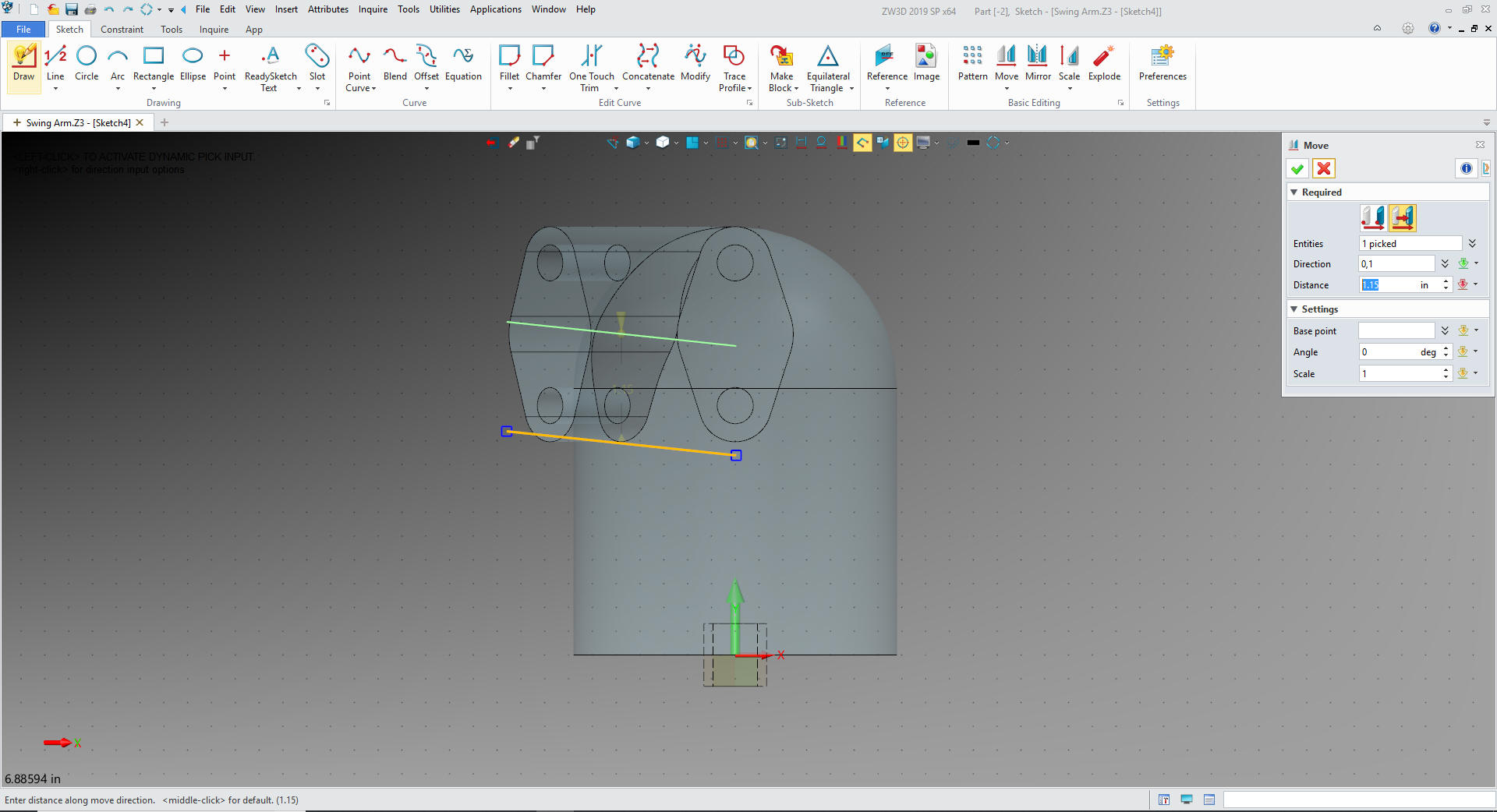
We
now edit the sketch for the centerline of the single boss.
Exit
the sketch and the boss is moved to the new location.
We edit the inside cylinder
We
delete the sphere and insert a new one at the center of the upper
face of the inside cylinder and we are done and just need to add the
fillets.
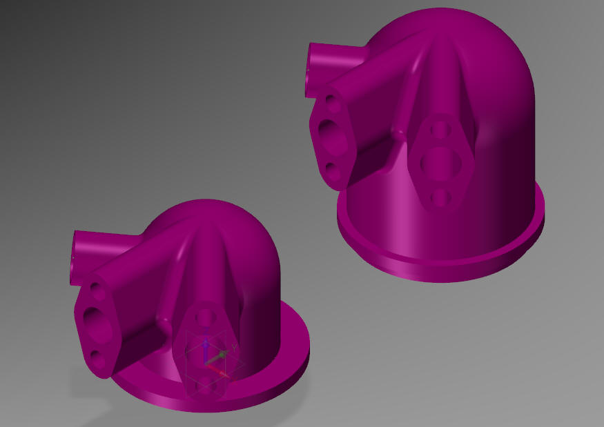
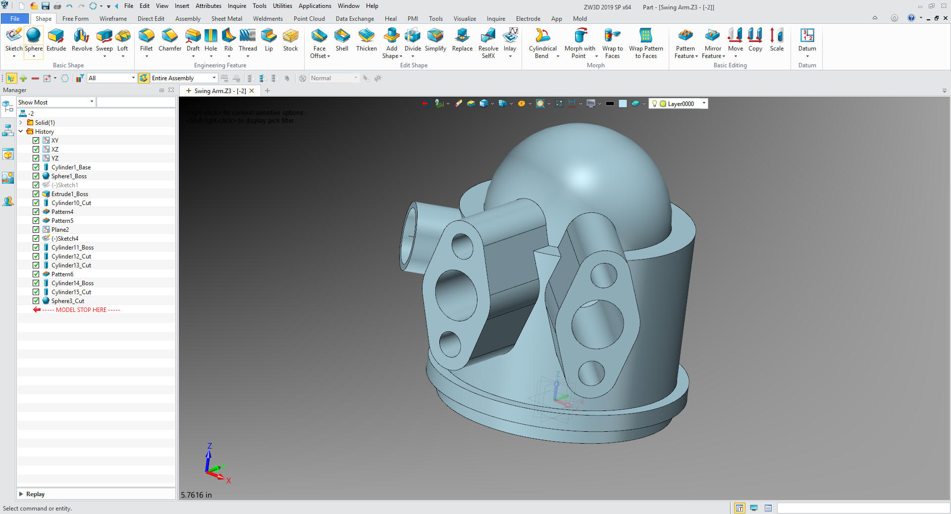
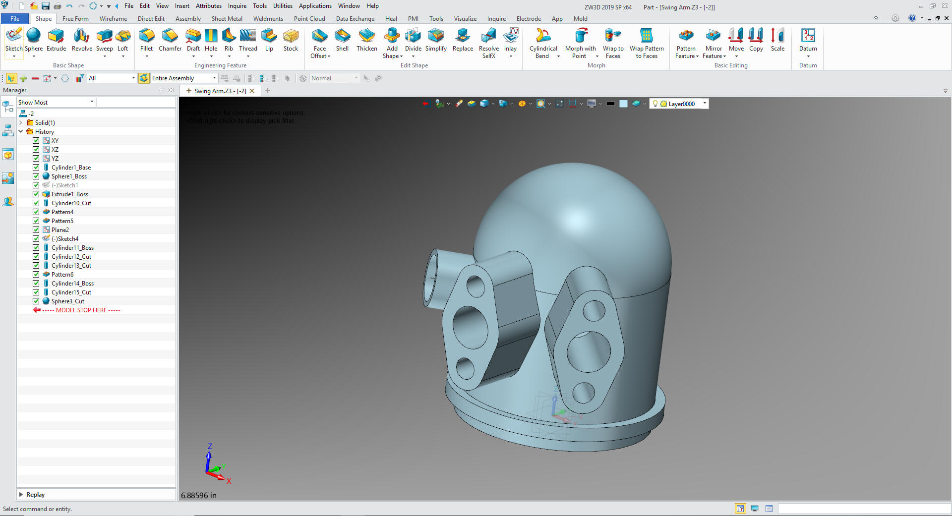
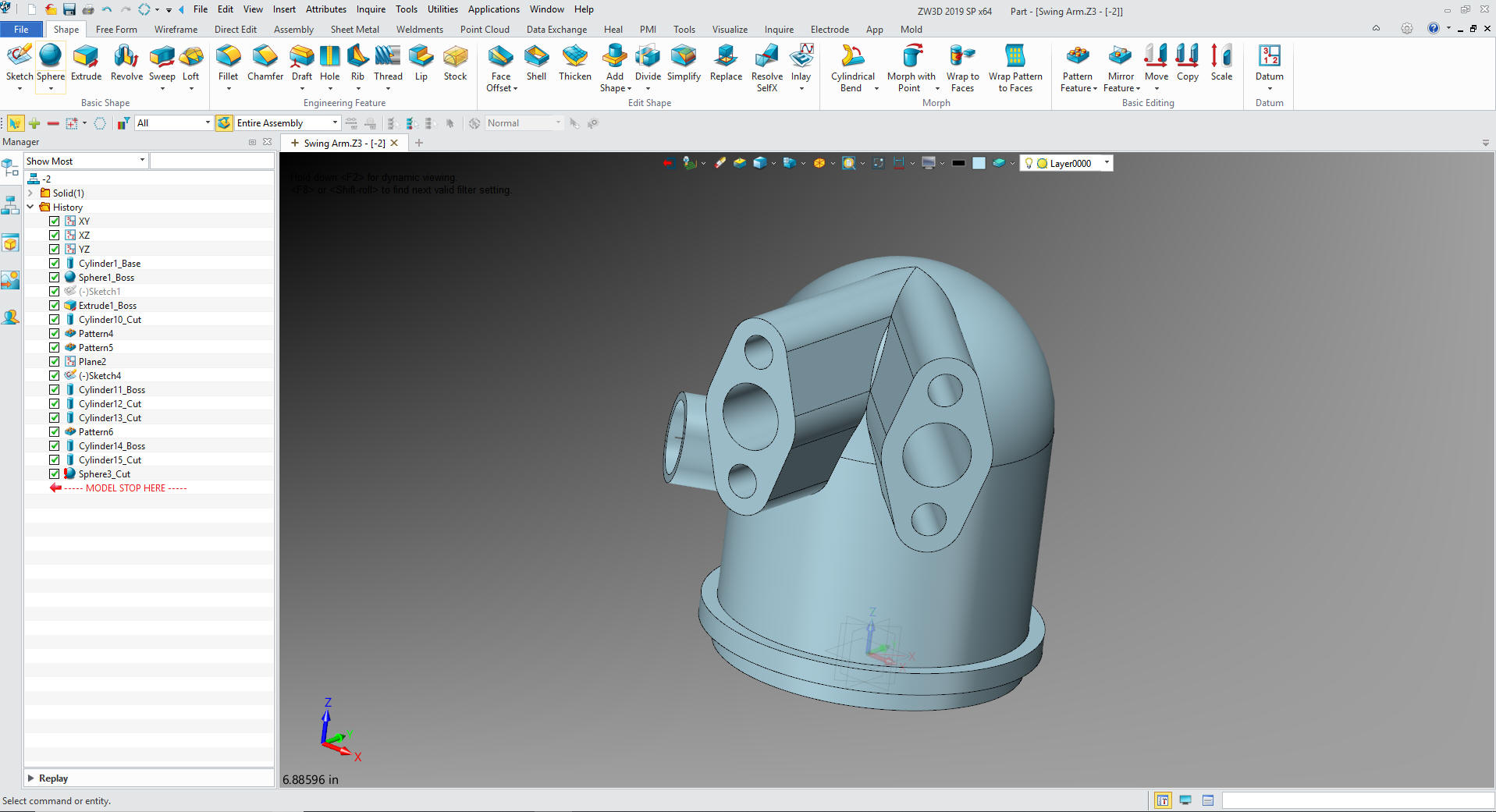
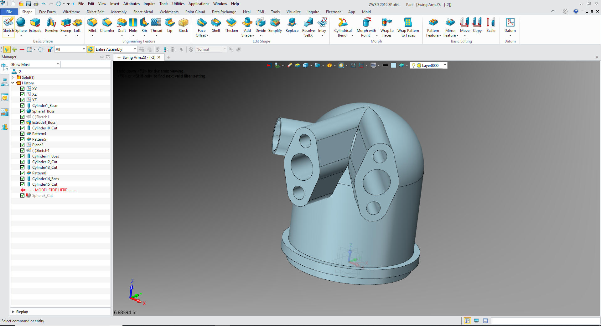
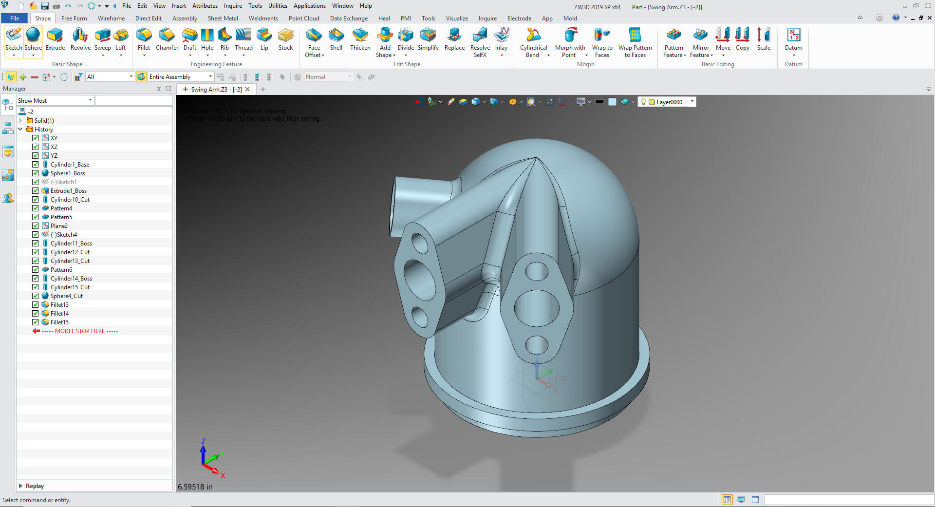
Here
is the the new -2 part, both in a single file.
Time
for the AIDS. ZW3D is the only history based system with a
multi-object modeling system with integrated AIDs. Imagine the PDM
Problems this would solve.
I created these two sheets with a
right mouse click and selecting 2D Sheet so I would have the two
sheets in one document. I will not go into the detailing process,
but it is a relatively easy robust documentation system.
I
just select -1 and set up and detail the AID.
Then
we add a new sheet and select -2 set up the sheet and detail the
AID.
Give me a call if you have any
questions. I can set up a skype or go to meeting to show this part
or answer any of your questions on the operation of ZW3D. It
truly is the Ultimate CAD/CAM System.
If you are interested in adding professional
hybrid modeling capabilities or looking for a new solution to
increase your productivity, take some time to download a fully
functional 30 day evaluation and play with these packages. Feel free
to give me a call if you have any questions or would like an on-line
presentation.