3D Modeling is the basis for our
engineering. That is the only place where productivity is paramount.
You can have all the PLM/MBE gurus debating data management, but it
does not add one smidgeon of productivity to the design process.
Top down or In-Context modeling is the most productive
feature of 3D CAD. Most systems tout this but each part is still an
external part. We are talking about a single model of multi-object
design environment. Both of the systems we represent offer this as
the "normal" design process. Thereby increasing your productivity 20
to 30%.
In these exercises I not only focus on modeling techniques, but
also on much more productive systems to do our designs. I hope you
enjoy them and learn something. If you are in management, understand
that all 3D CAD systems are not the same. Cutting your engineering
costs is very simple. Even your legacy data is not a problem. Please
feel free to give me a call. There are millions of man hours wasted
every day with poor modeling techniques and dated 3D CAD
systems that cost a fortune. Productive 3D CAD systems do not have
to be expensive.
Joe Brouwer
206-842-0360
I am doing the below assembly for
an exercise showing my modeling techniques and, of course, my 3D CAD
solutions.
3D CAD Modeling Techniques
When I introduce IronCAD's very
flexible design paradigm I have a hard time to get the Pro/e clone
users, like Solidworks and other programs to understand the drag and
drop design paradigm.
I saw the
following video challenges on linkedin and thought I would give it a
try on IronCAD. This will give you an idea how different
and flexible IronCAD is compared to the conventional Pro/e clone.
These exercises have become incredibly
popular and I have follow up by showing more examples of
this 3D modeling technique!
IRONCAD vs Fusion 360
IronCAD vs Solidworks
ZW3D vs Creo
ZW3D vs NX
ZW3D vs CATIA
ZW3D vs Inventor
These exercises started out to show the benefits of IronCAD over
these systems, but
quickly turned into a study of modeling techniques. Take a look at all of
them, they will open your eyes to a much different and more productive way of
modeling. It really has more to do with modeling technique than it has to do
with the 3D CAD systems. I have found that I do 3D modeling as compared to
the conventional 2D sketching. Of course, having a more productive 3D CAD
system doesn't hurt.
These exercises were incredibly
popular and I thought I would follow up by showing more examples of
this 3D modeling technique.
We will be doing a
couple of parts each weekend in both IronCAD and ZW3D. I hope you
enjoy these exercises and hopefully they may lead to increasing your
productivity.
Please feel free to review the
prior lessons:
3D Modeling Techniques IronCAD Lesson One
3D Modeling Techniques IronCAD Lesson Two
3D Modeling Techniques IronCAD Lesson
Three
We have a couple more parts to add to our assembly. The true
single model environment is by far the most productive feature in 3D
CAD. Watch how easy it is to design parts in context or top down.
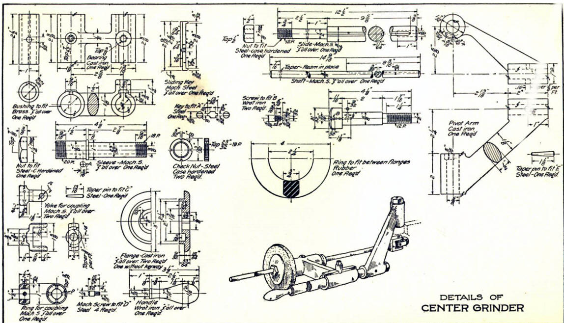
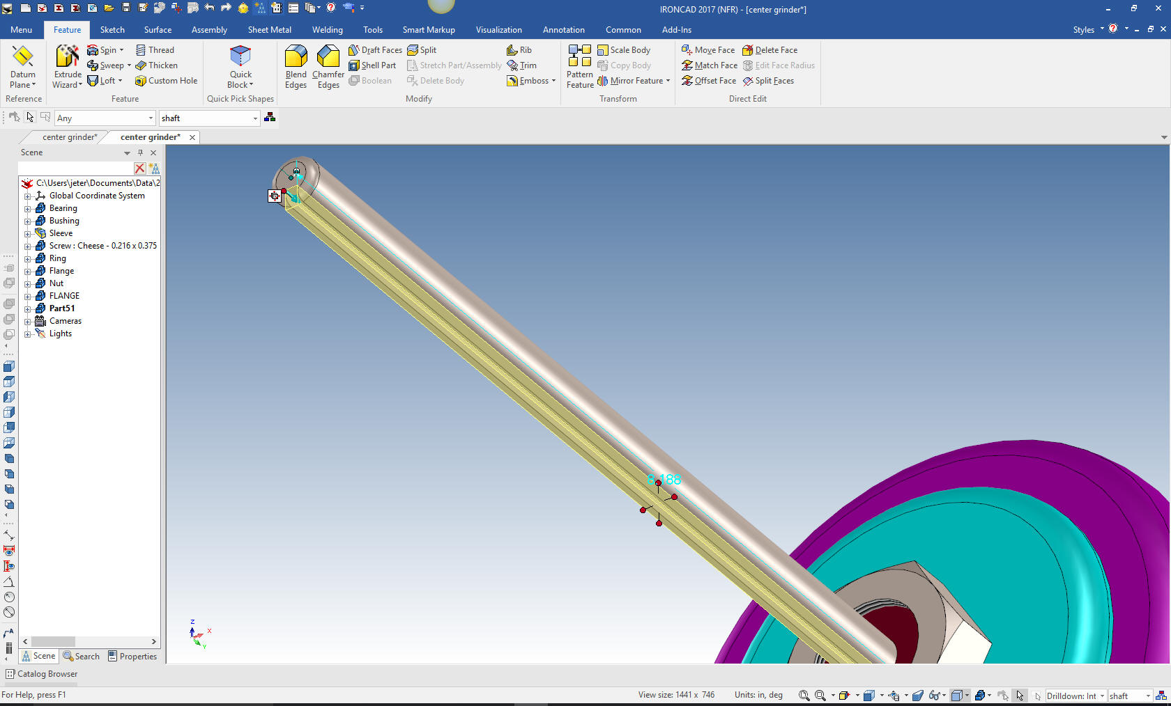
We are going to model the Shaft. First we create a
configuration called "Shaft". With a single model environment
this is how you differentiate the parts for detailing and viewing
assemblies. You can have any level of configuration. This is much
better than using levels as it is done in other single model
environment programs.
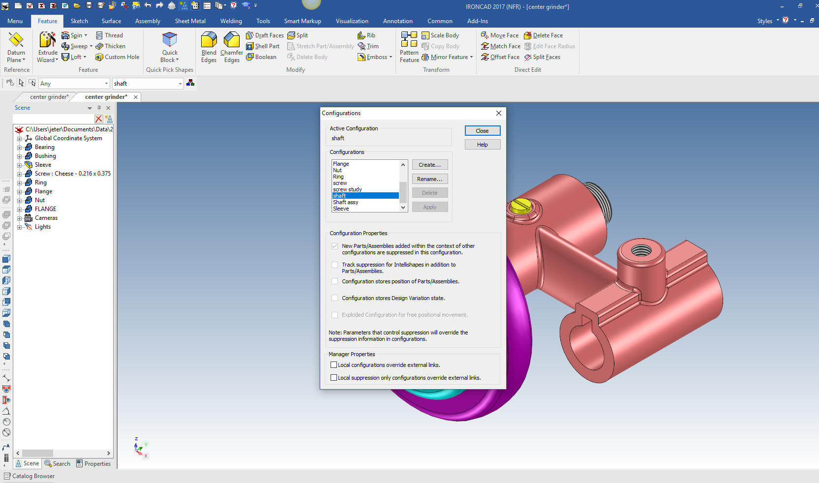
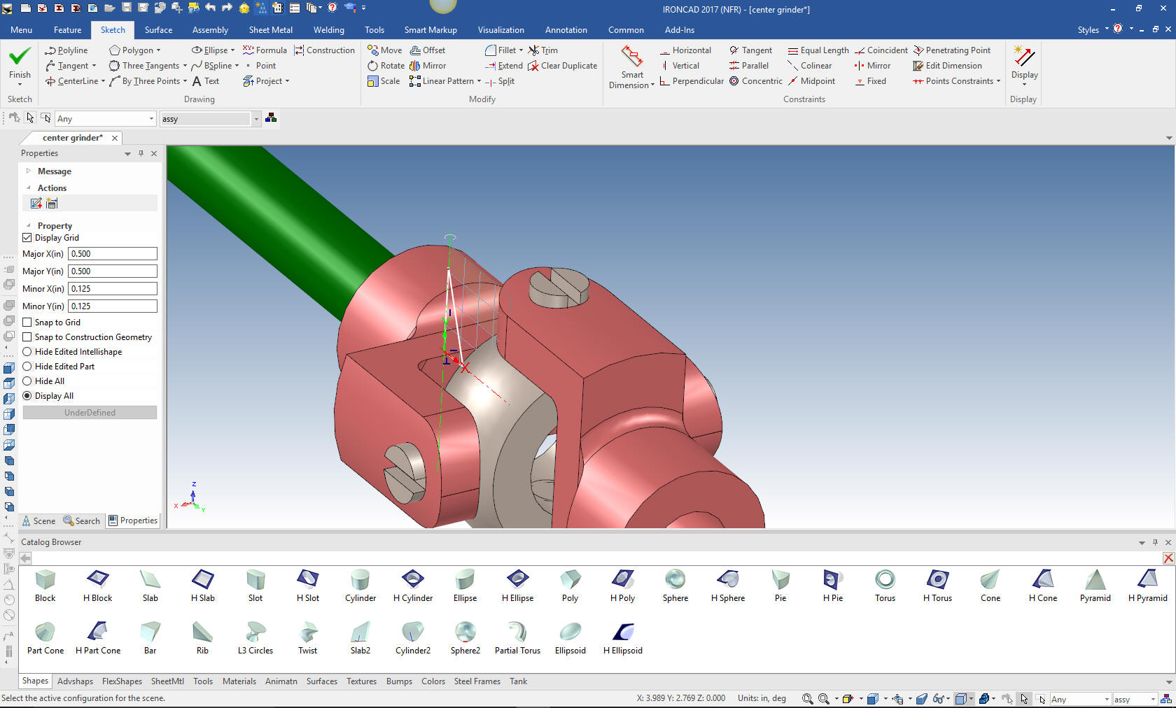
With the extrusion wizard we establish a
plane on the mating face and project the mating edge on to the plane
and select stand alone to create the new part. We do not concern
ourselves with sizing it now, we can push/pull it to the correct
length later.
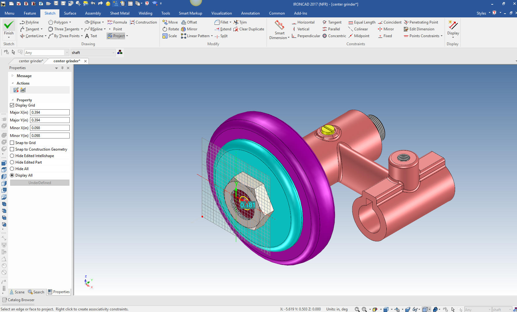
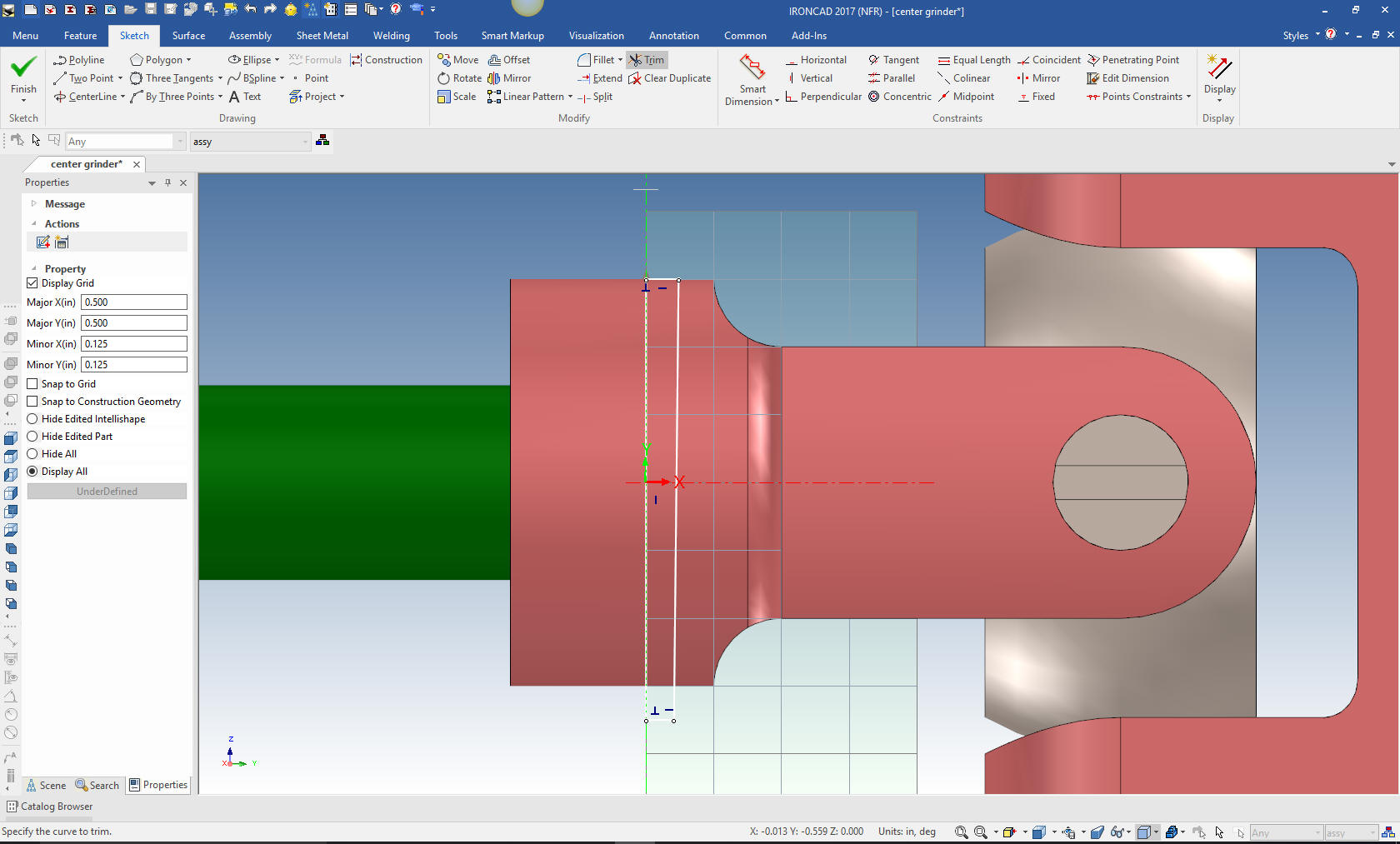
We select okay and push/pull the shaft to
the correct length.
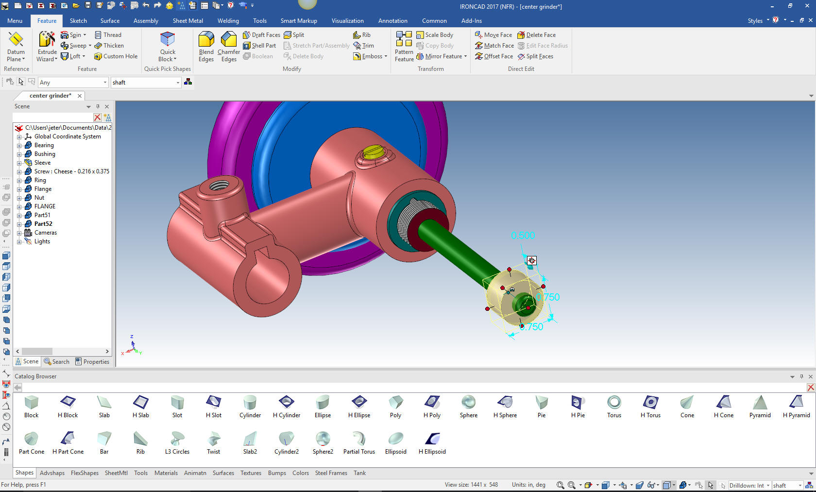
We put the groove on the bottom by drag and dropping a hole block on
the end of the shaft. We size it by editing the handles.
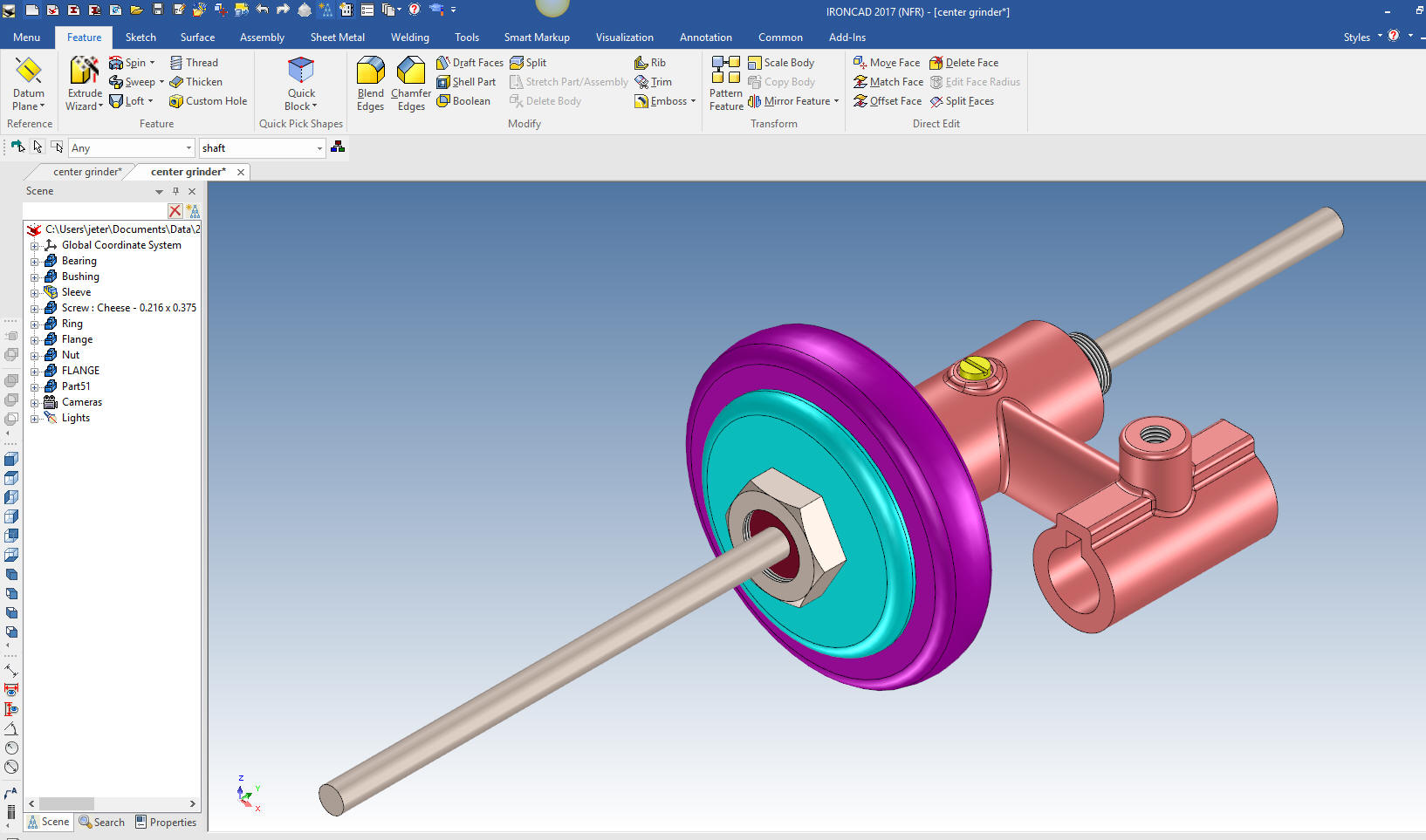
We are
done with the Shaft and now for the Yoke, and I am not Yoking, LOL. We
drag and drop a cylinder on the end face of the shaft with the right
mouse button that allows you to select a new part, locate and size
it.
Note: The catalog is so incredibly powerful, its
productivity can not be denied.
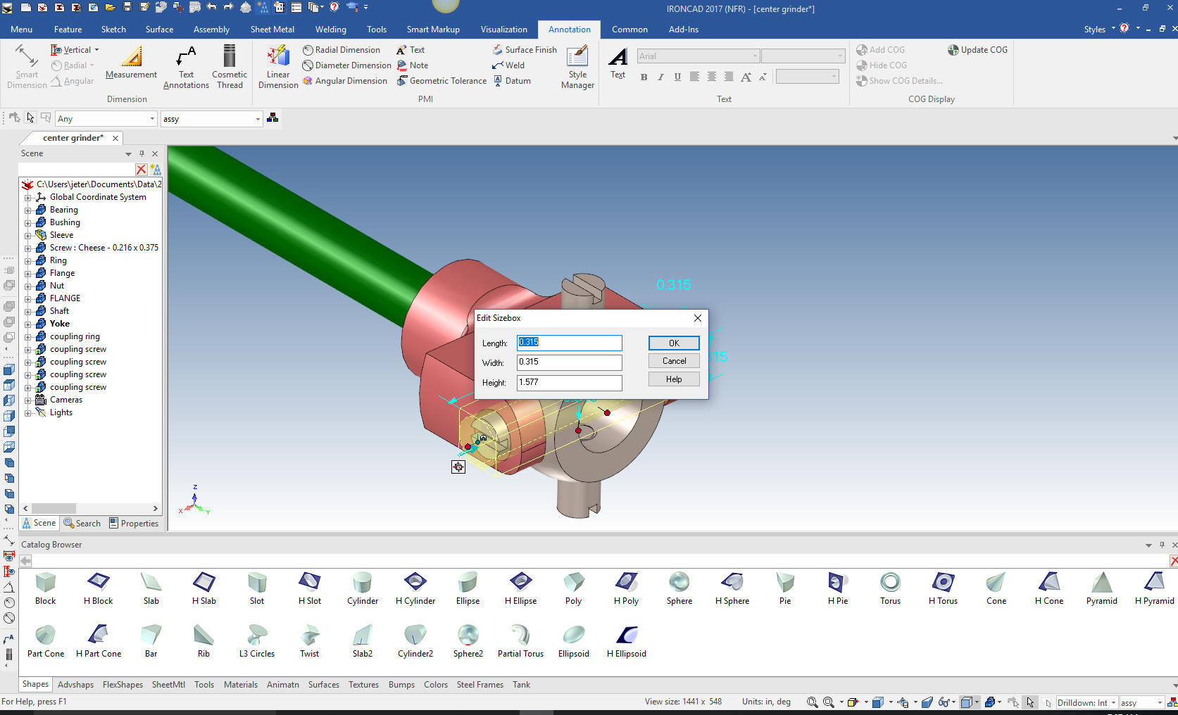
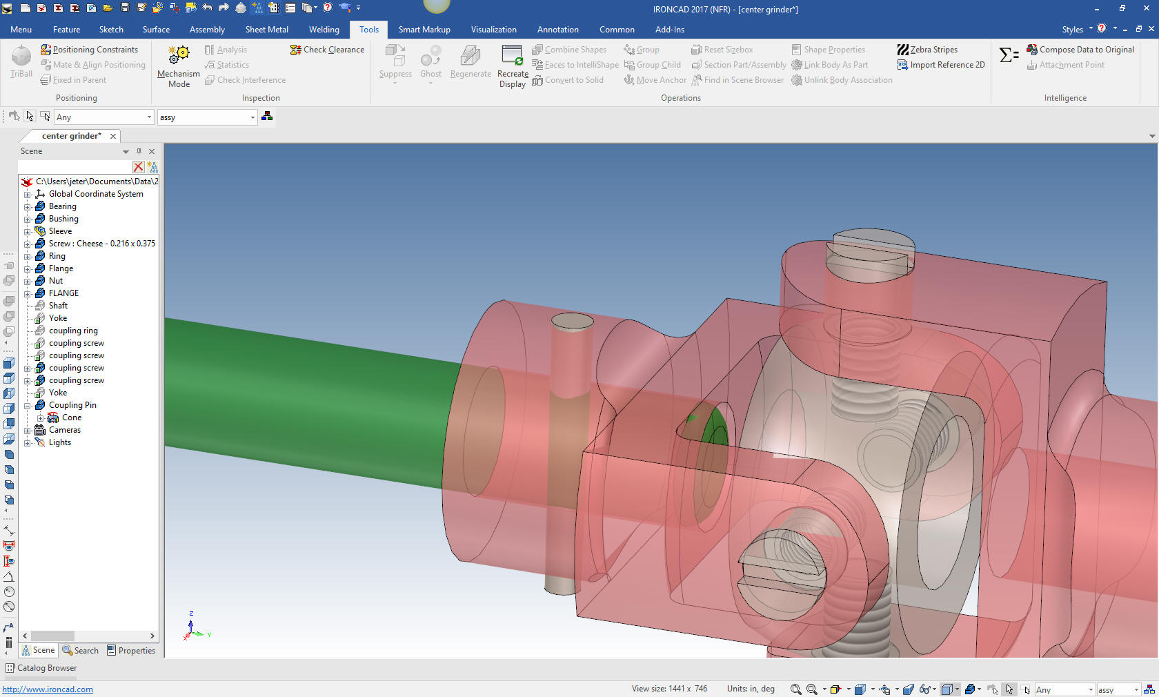
We hide the shaft and drop another cylinder on the center of the
face of the last cylinder and size it.
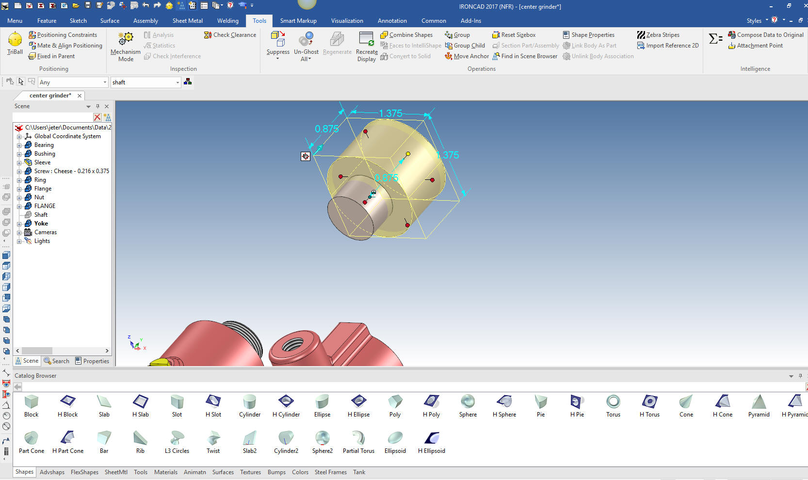
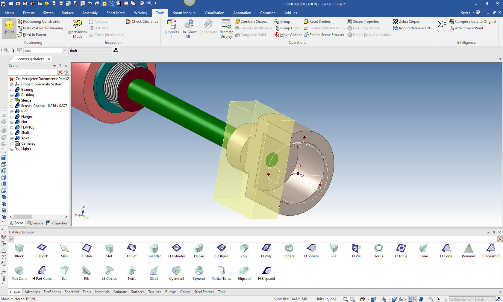
Now we just drag and drop a hole cylinder on to the center of
the face of the cylinder and size it.
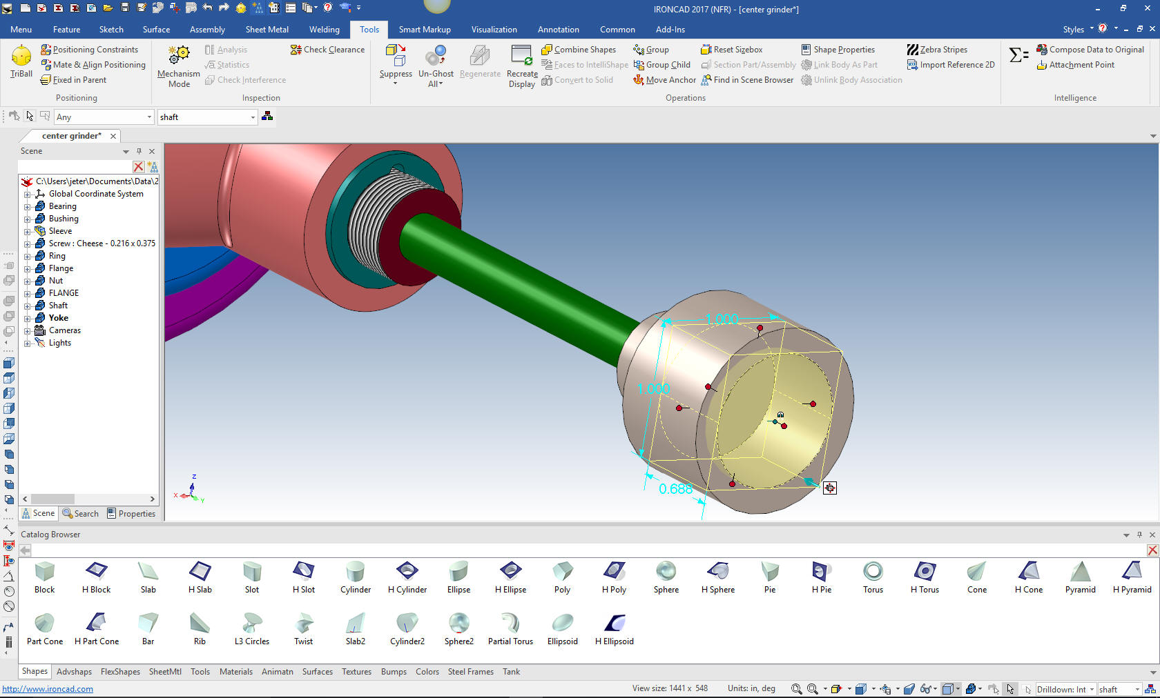
We
will now drag a hole block on to the face and size it.

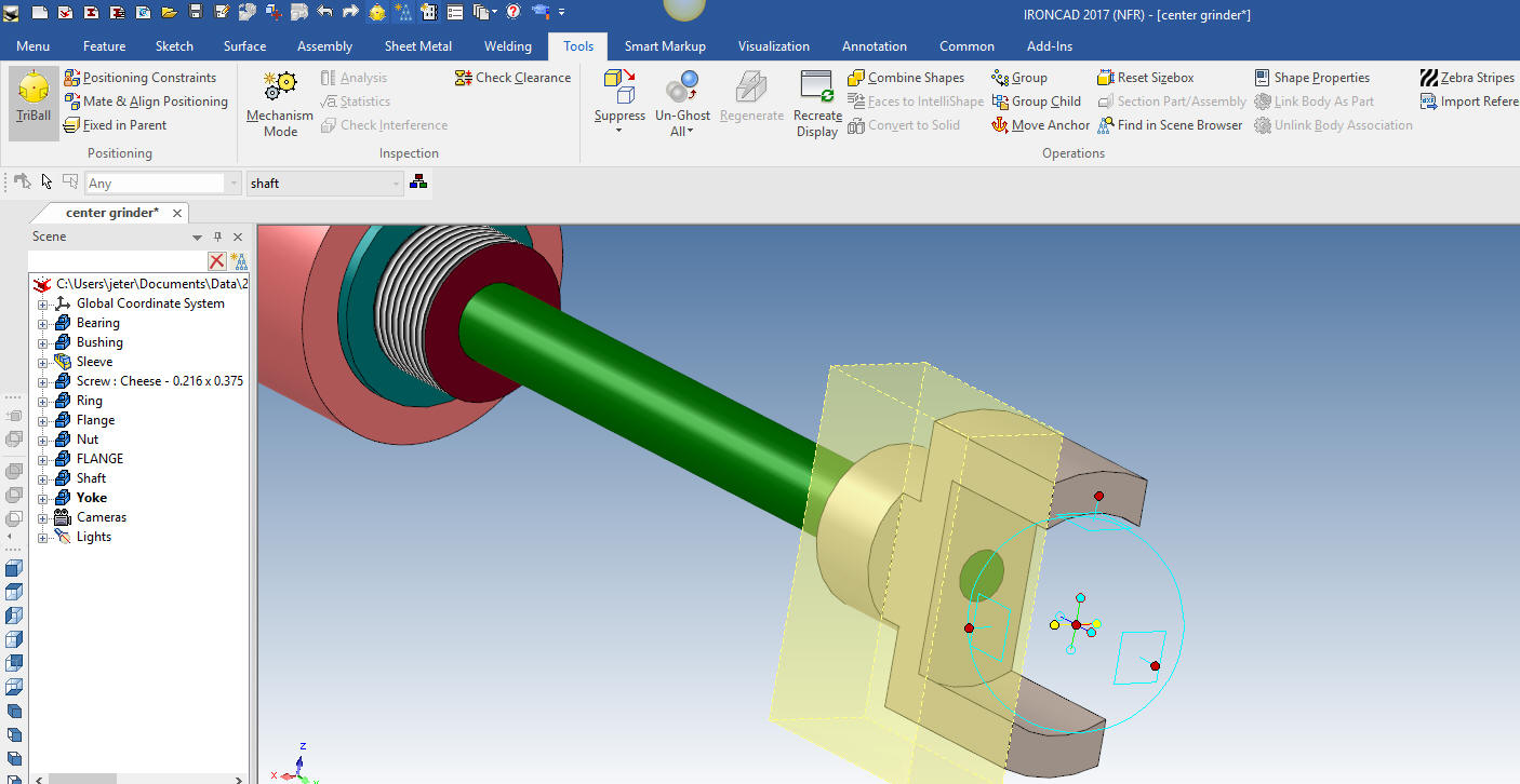
While
the whole block is active we turn on the triball, hit the spacebar,
which allows locating the triball only for the next step.
Note: The triball was the first feature, part and assembly
manipulator. Even though many programs offer this function, none
have come close to this very productive, even though simple, very
sophisticate tool. IronCAD, if anything else, is a very clever
program.
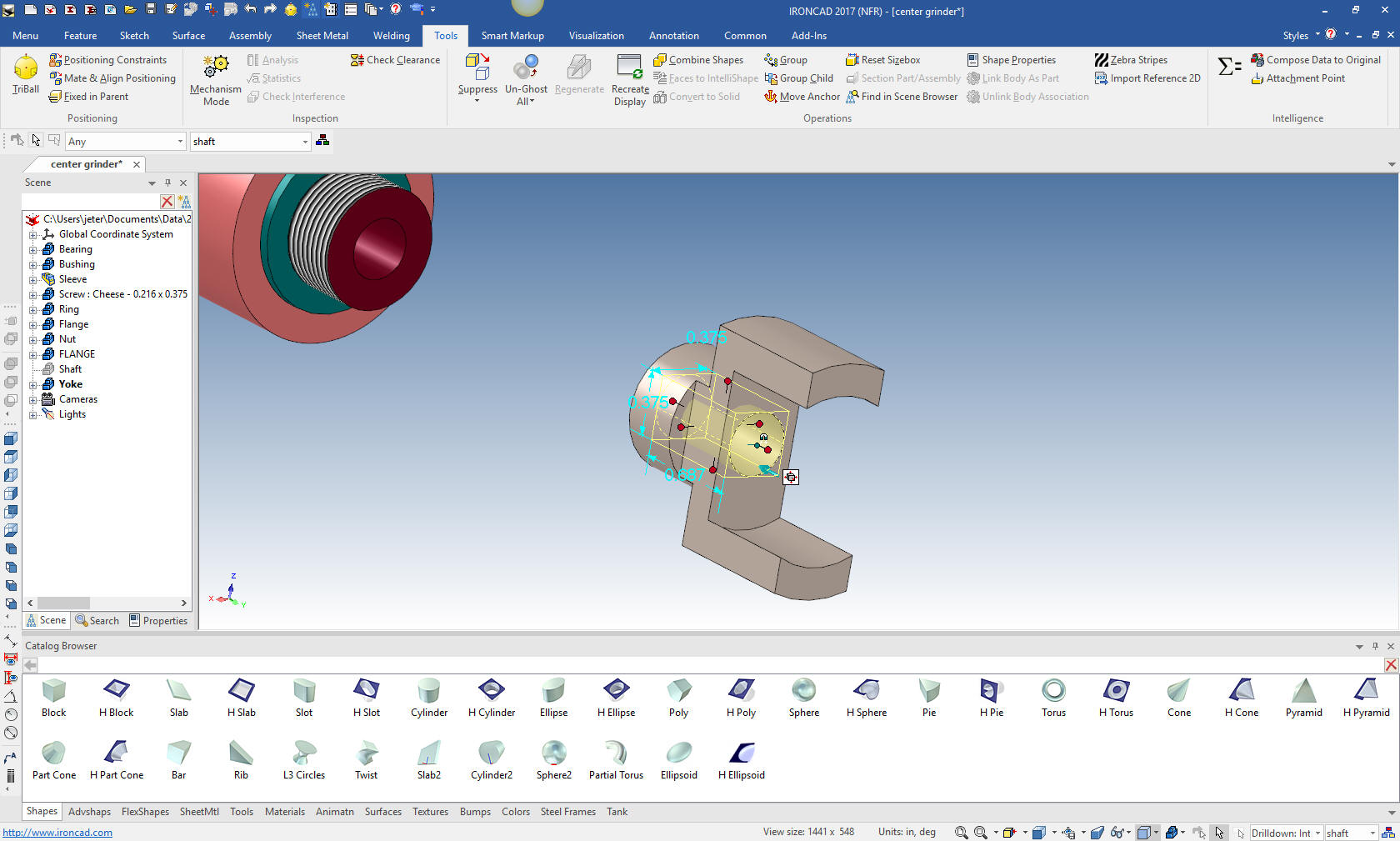
We hit the spacebar again making the
triball functional. We select the inside axis with the right button
and select mirror link. This copies the feature and links it, so any
changes to either will be reflected in both.
We hide the
shaft again and drag and drop the hole and size it.
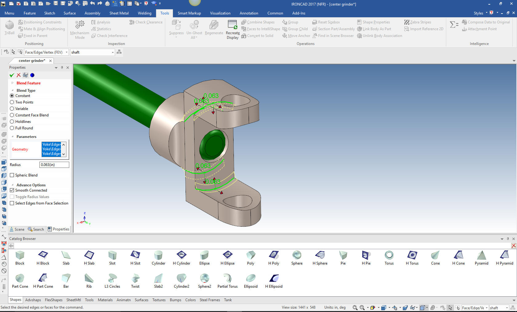
We add the blends and create the hole again using the triball. We
drop it on any face and rotate it and move it into place and pull it
through both features. Notice the axis that is highlighted, there is
not system as flexible as IronCAD for manipulating features, parts
and assemblies.
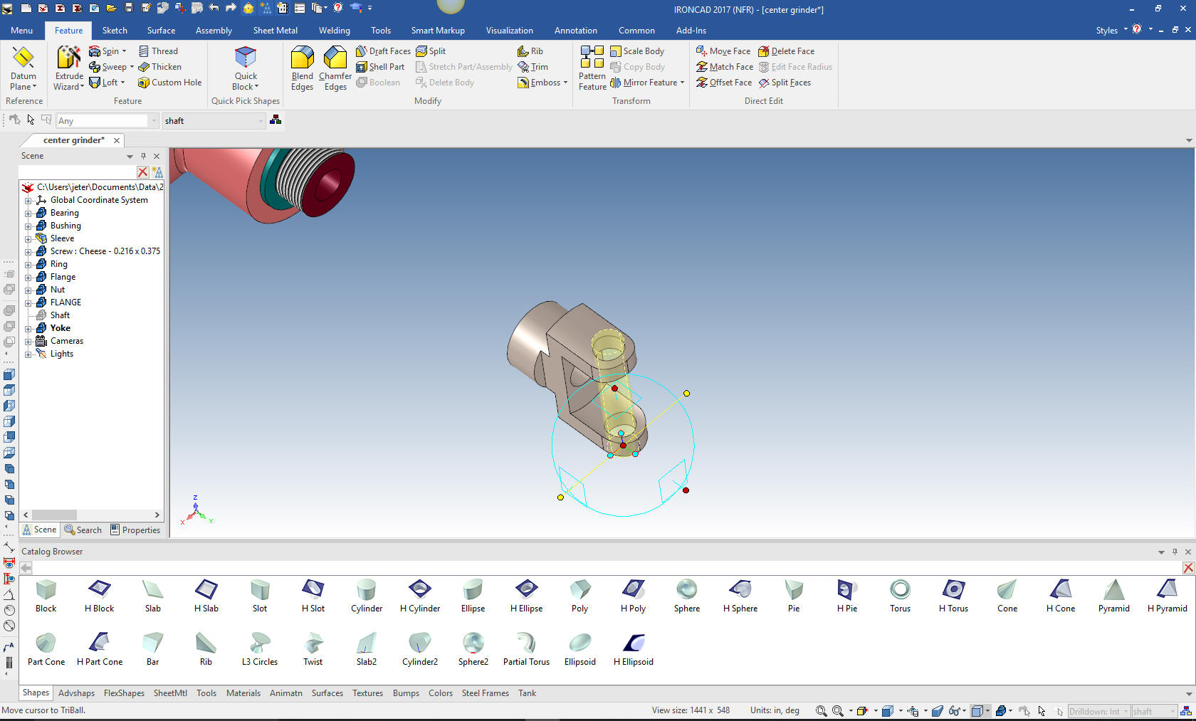
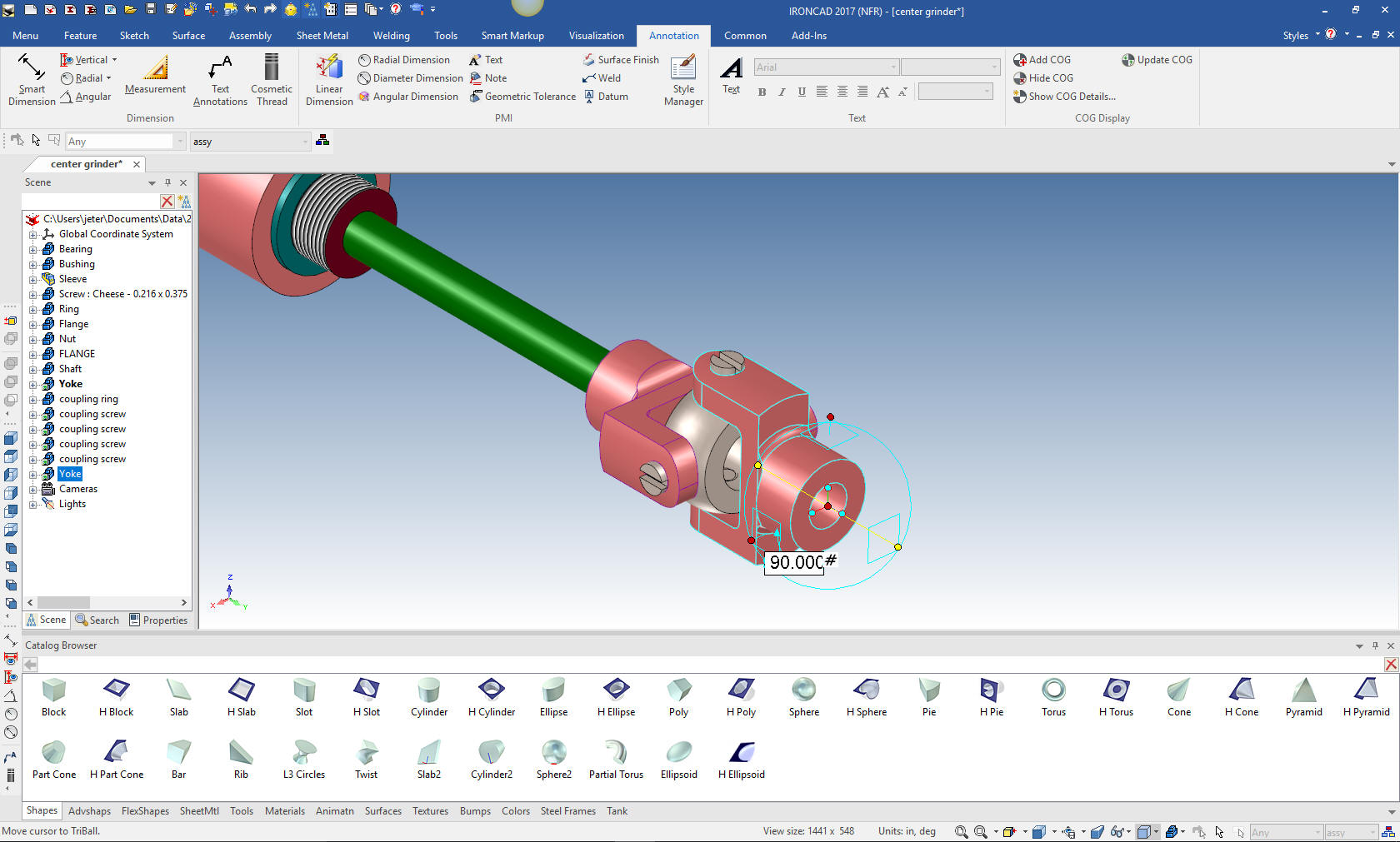
Add a few blends and we are done with the yoke. I will unhide the
shaft.
Ooops, the yoke needs to be rotated 90 degrees. No problem, using
the triball it is a snap.
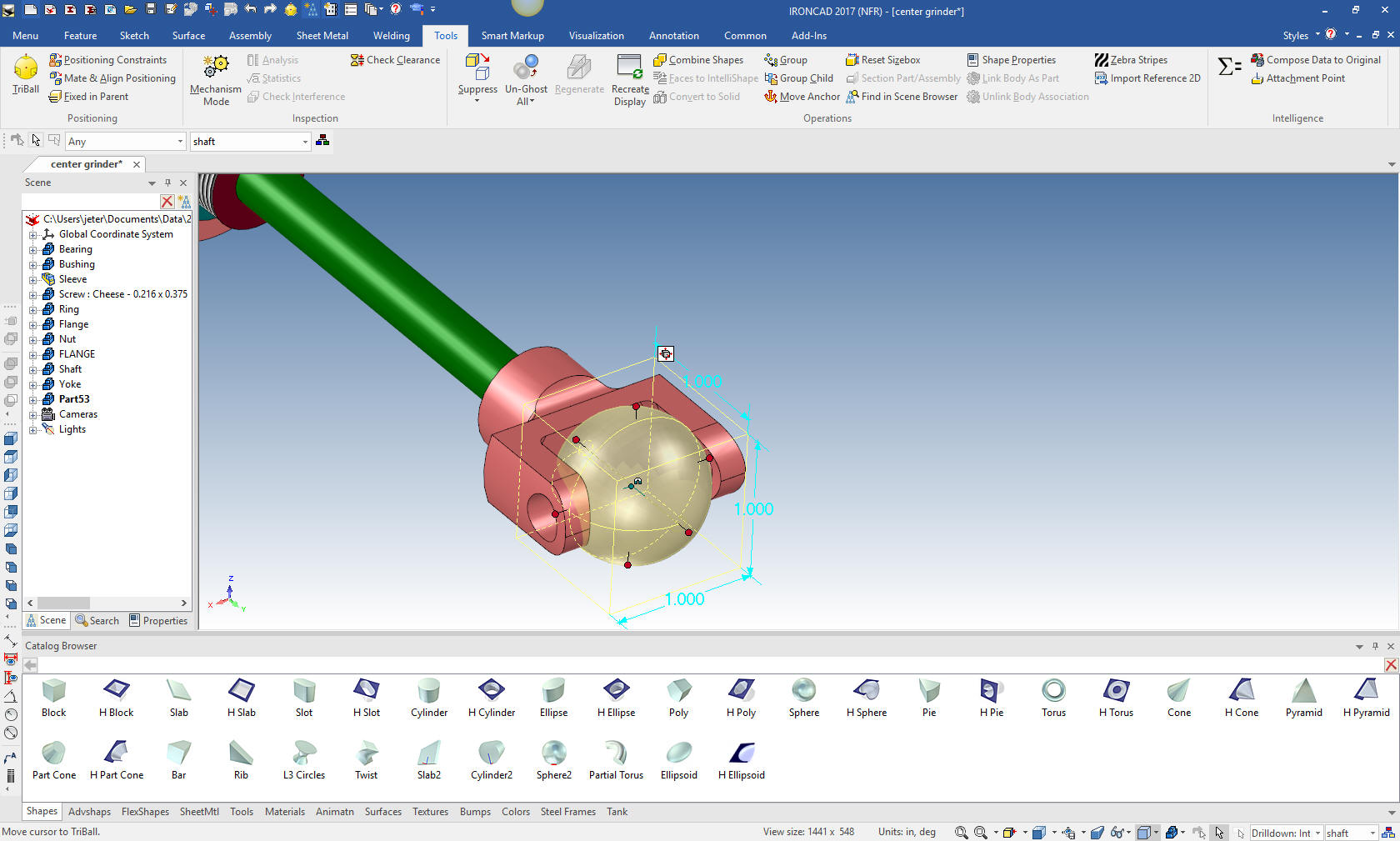
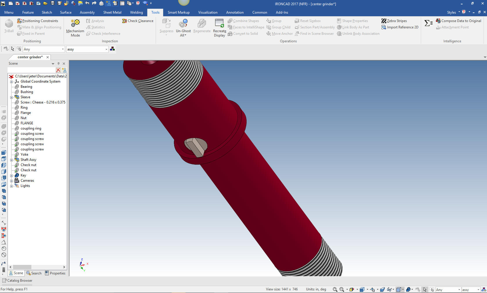
Now for the Coupling Ring. We drag and drop a sphere, using the
right mouse button with the option to create a new part, locate it
and size it.
We drag and drop a hole block on to the face of the sphere.
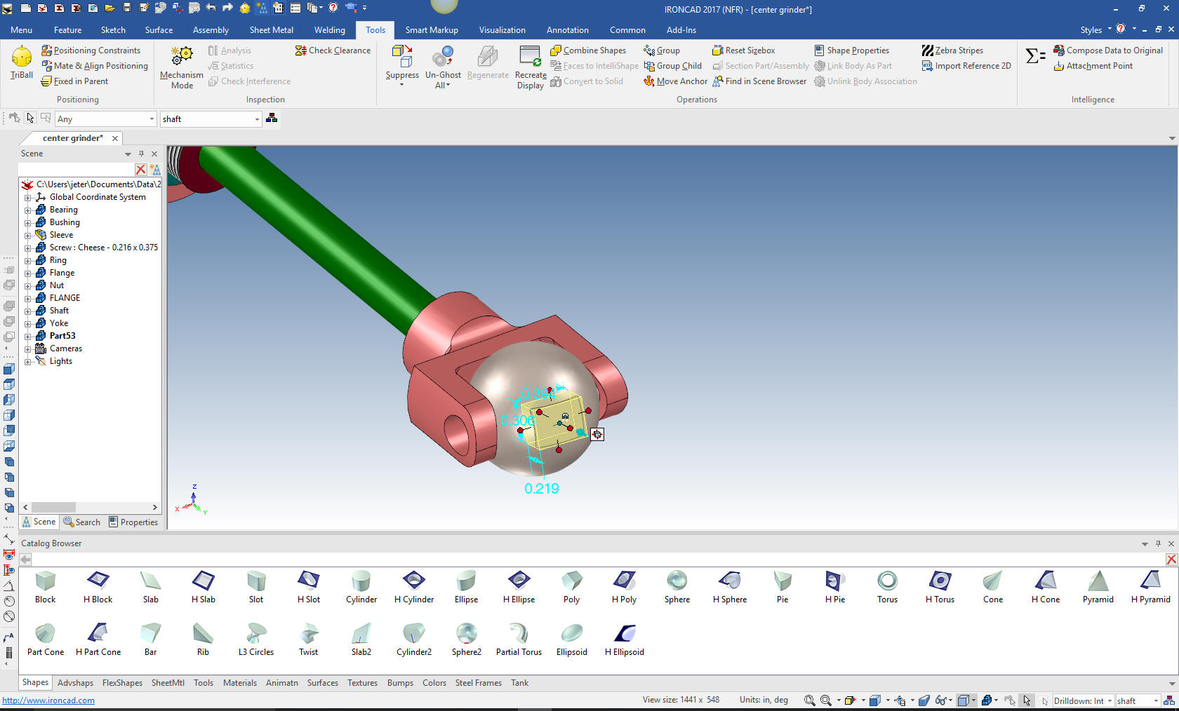
I
comes in catawampus, but no problem. As I have been telling
you the Triball is truly incredible. I was still learning things
about it years after I started using IronCAD over 20 years ago. We
just turn on the triball and right click inside the circle and
select "Orient Triball to global" and viola!! It is ready to
push/pull into the correct shape and location. This is huge!

I
will size the block and mirror link it.
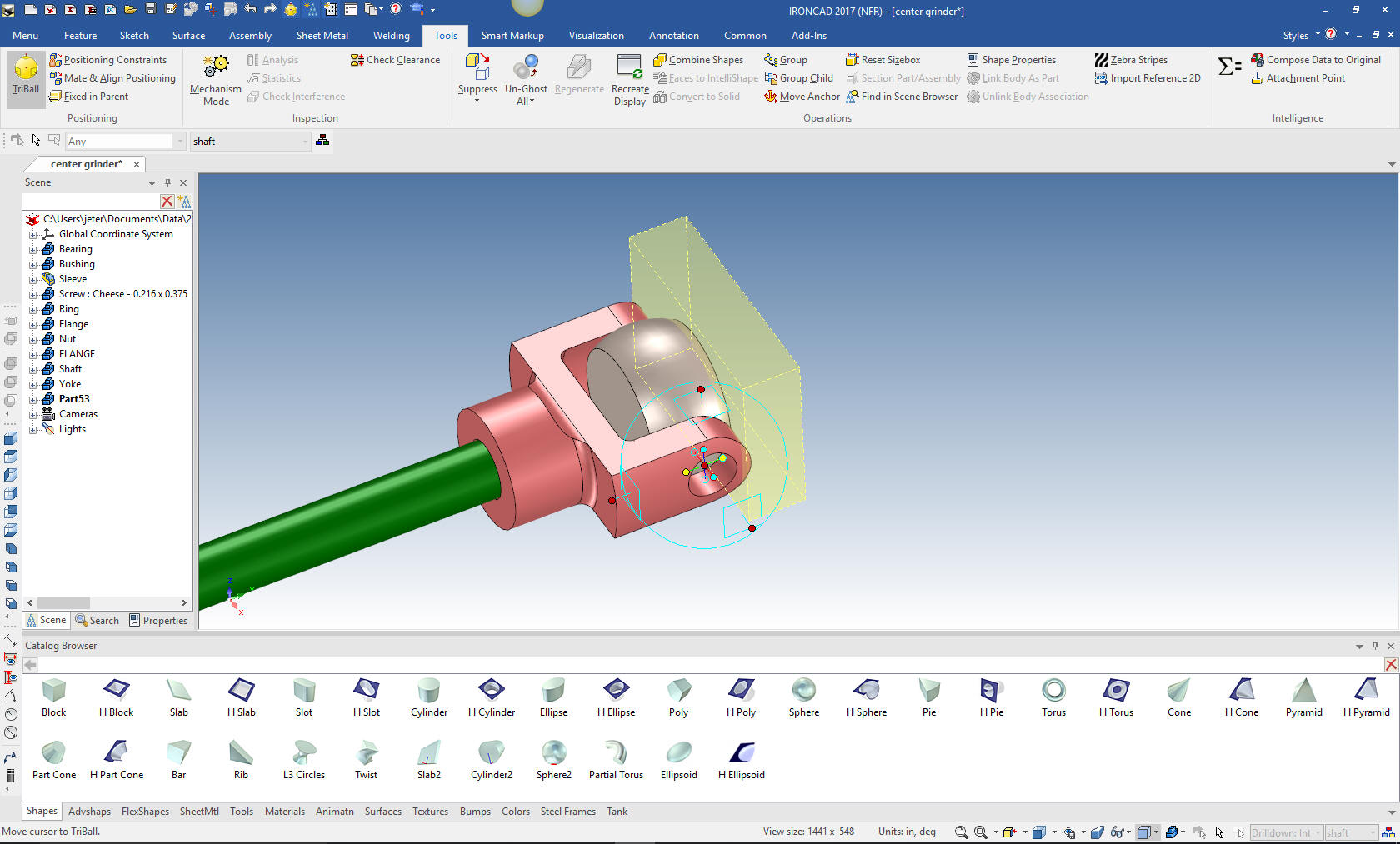
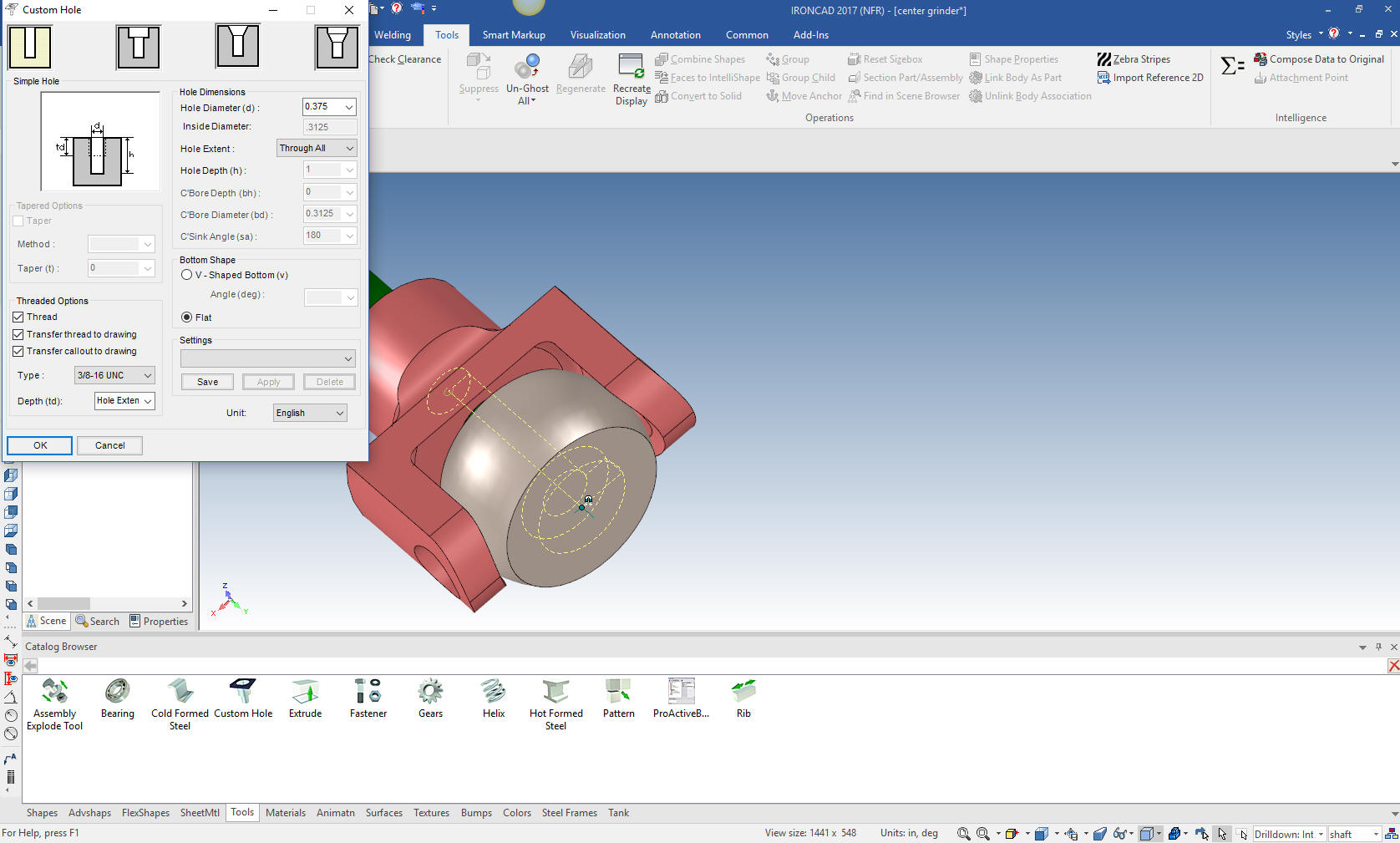
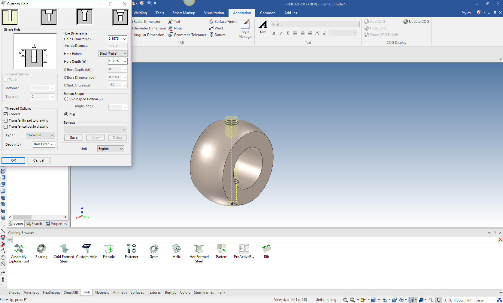
I drag and drop a hole from the catalog. Tools>custom hole. I
drag it on to the center of the face of the part. I know this all
seems very strange to you Solidworks clone users but it is the way
of the Force! Yes, you have a completely different mind set when it
comes to modeling. It is like a completely new dimension of freedom.
We
just take the hole and locate and link the other holes with again,
the fantastic Triball. I can not tell you powerful this one feature
is.
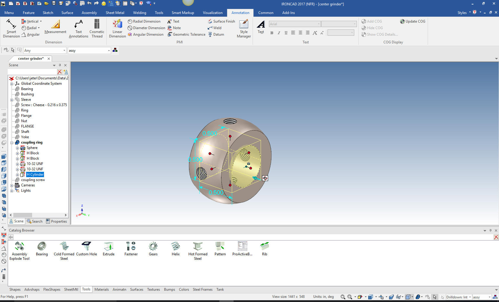
Now drag and drop a hole cylinder to the center of the faces and
size it.
Note: IronCAD has common points that you can drag
and drop. Center and mid points and ends to make it very easy for
locating the feature, part or assembly.
You can custom
catalogs where you can drag and drop feature, parts and assemblies
from the scene (workspace) into the catalog. It is called a scene
because IronCAD started out as a graphic design program called
Trispective. This fact alone, make IronCAD much more than some
engineering design program.
IronCAD has a modeling only
package that offers many in the companie access to the engineering
models for a variety of reasons.
Leverage Your Engineering Data - Sales, Publication and Marketing
We are done with the Coupling ring. now for the screw. We drag and
drop a cylinder onto the face of the yoke for orientation only. We
size it and drag another on top and size it, drag a hole block and
size it for the driver groove. We add some cosmetic threads and we
are done.
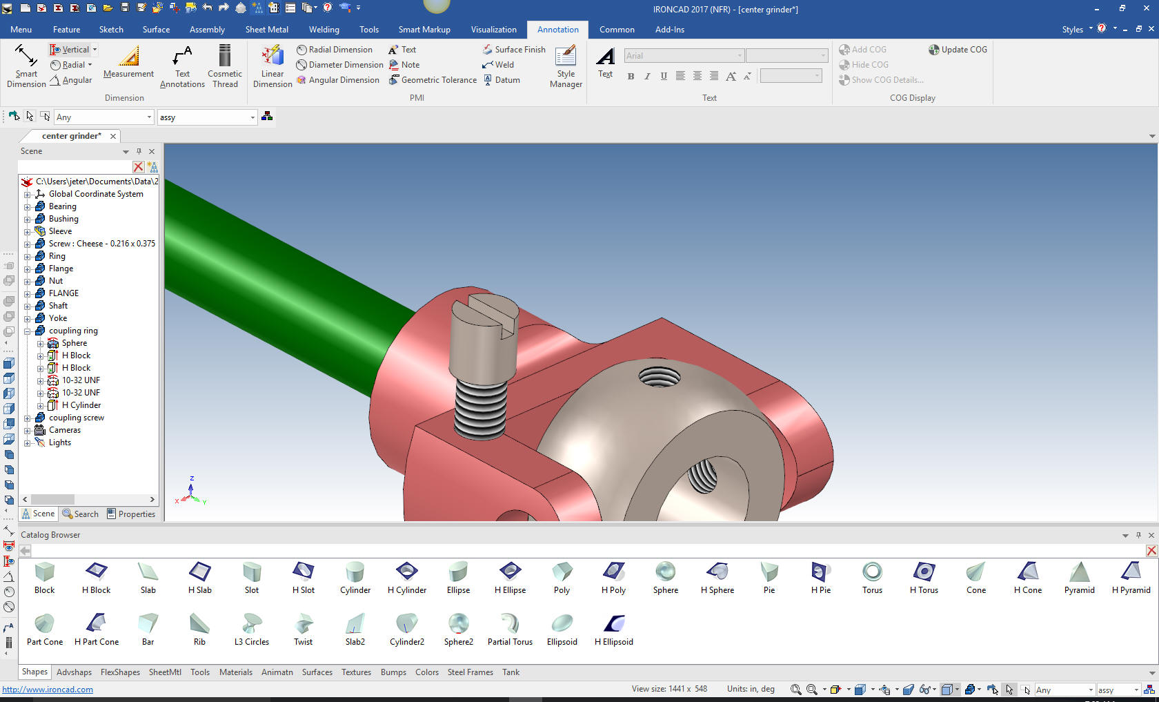
We
locate the screw and rotate and link using the Triball. Oops I
noticed that the hole in the yoke was incorrect. No problem we just
select the feature in the scene and edit it. Notice how easy it is
to correct small or even large errors on the fly.
Now,
using the triball we link a new yoke. We rotate and locate it.
Notice we now have 3 new linked screws and one yoke in the history.
Now for the tapered pin. Just drag and drop a cone with the
right mouse button an select new part. We can now edit the cross
section. Remember that all of the drag and drop shapes are based on
editable sketches. This is such an easy way to make a revolved part.
I am shocked that drag and drop was not implemented in the
Solidworks clones. I am still wondering why anyone stays with that
dated paradigm.
Now we
will edit the cone by deleting the existing graphics. We will
project mating edges for actual construction and reference.
All I
do is select okay and I have a new part, Coupling Pin. I rename the
part in the history and create a coupling pin configuration.
The
shaft, yoke and pin are actually a inseparable assembly. So we will
create the assembly in the scene browser (history tree)
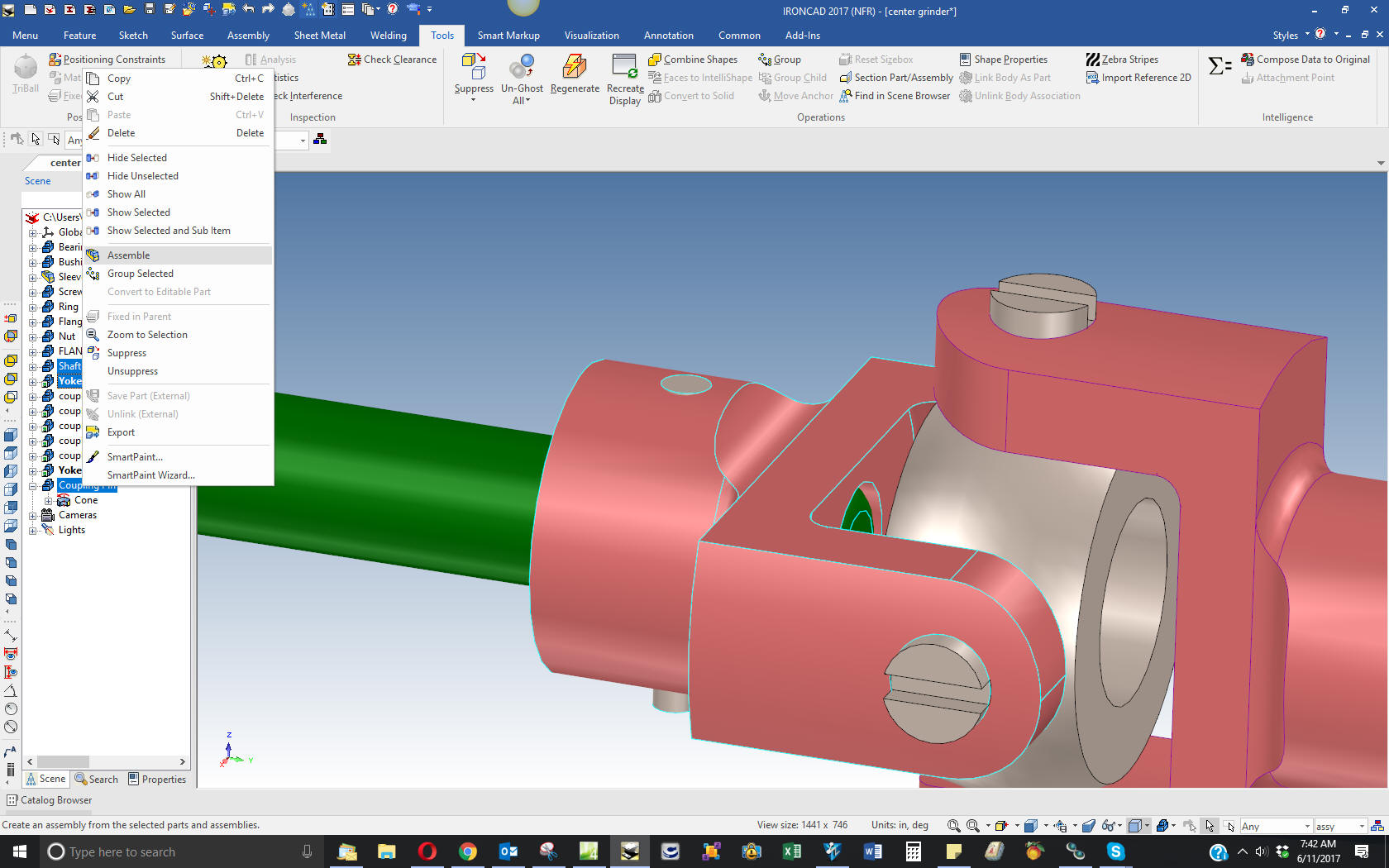
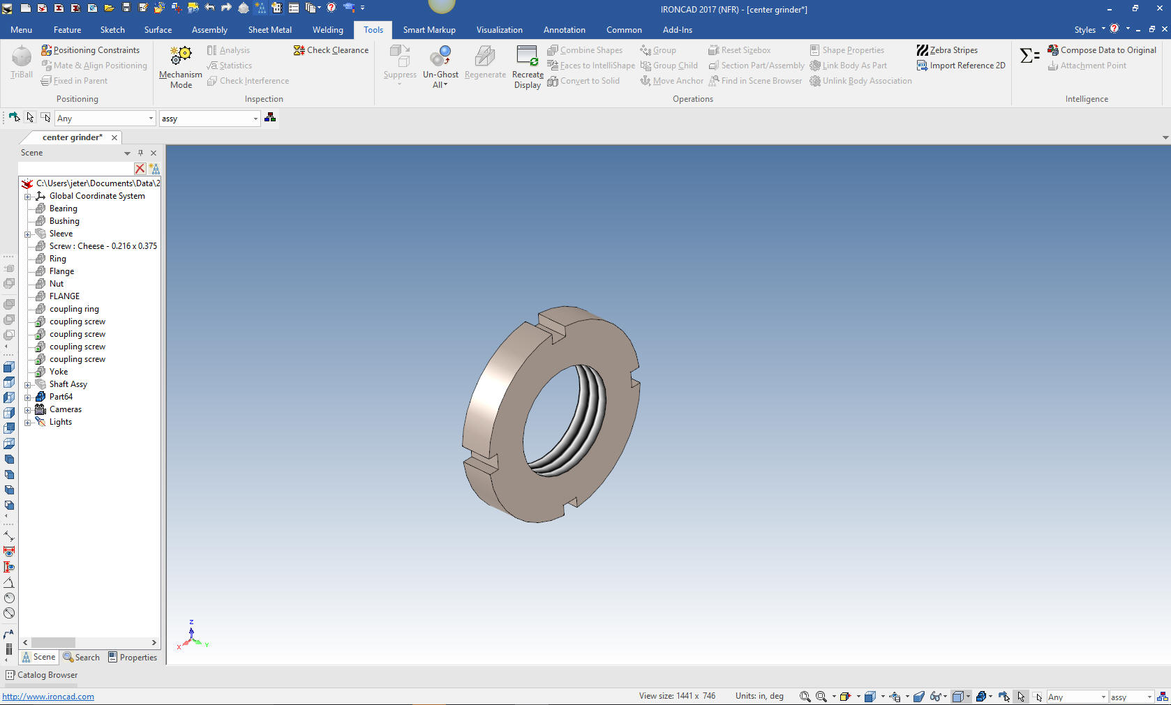
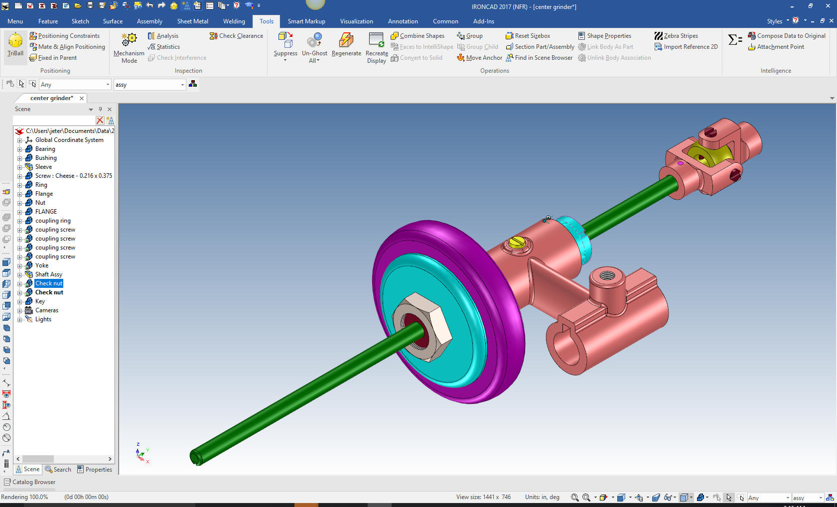
Now
for the check nut. I am sure most of you have got the idea. I drag
and drop a cylinder locate and size it, drag and drop a hole block
locate and sized it, rotate and link. Then drag and drop a threaded
hole.
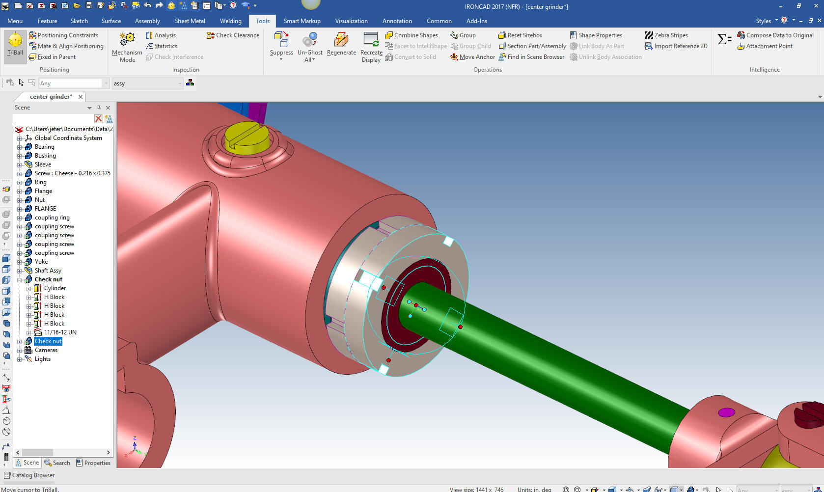
With the triball we will link a new check nut in place and
rotate it for clarity.
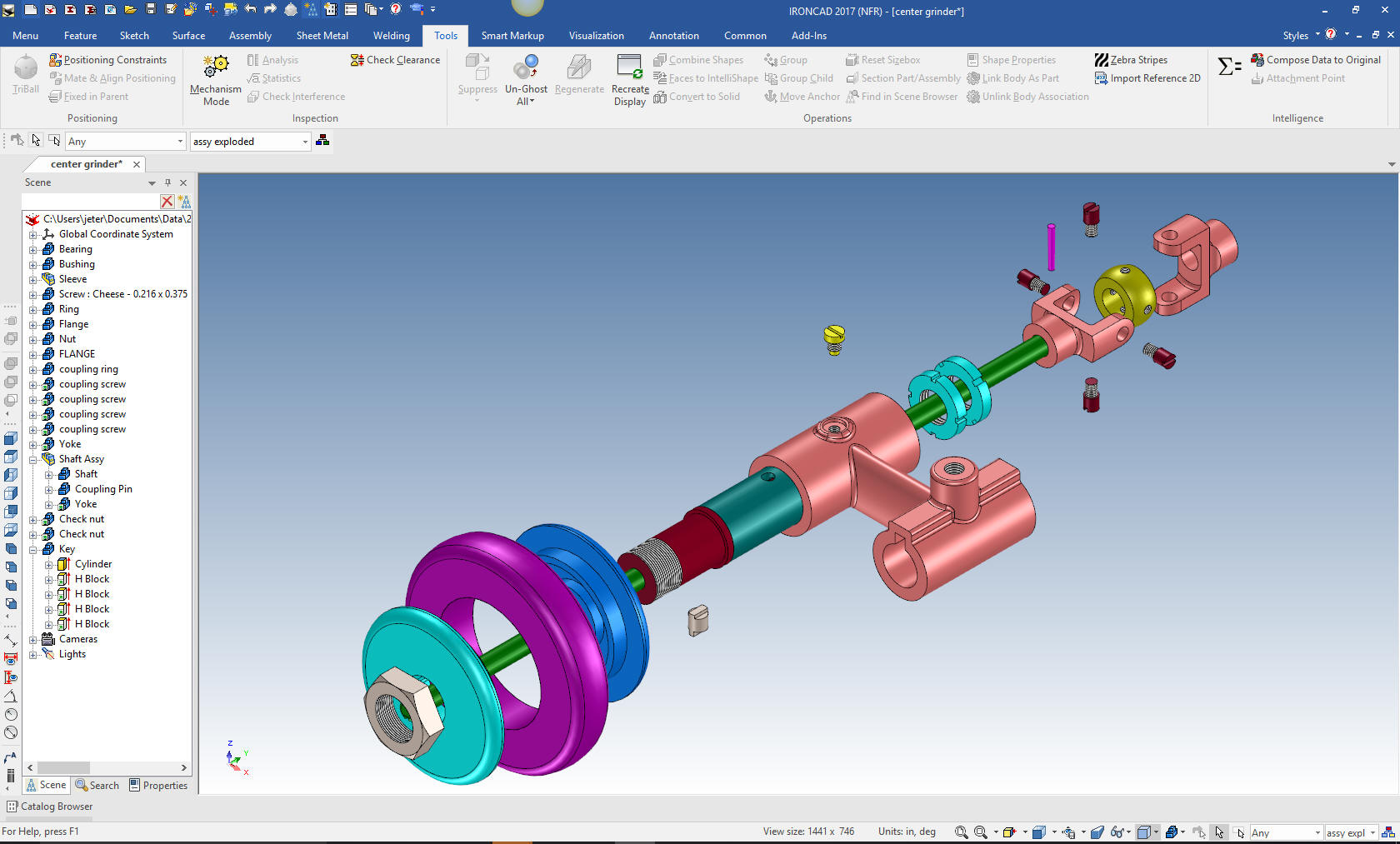
The last part the Key. We drag and drop a cylinder and make the
appropriate cuts.
We are
done with all the parts we are going to create.
We
can use the existing exploded view to move the other parts into
place with the triball.
I am
going to detail these parts in one sheet. Ironcad allows all of the
parts to be detailed in one document. Great for one person doing an
assembly.
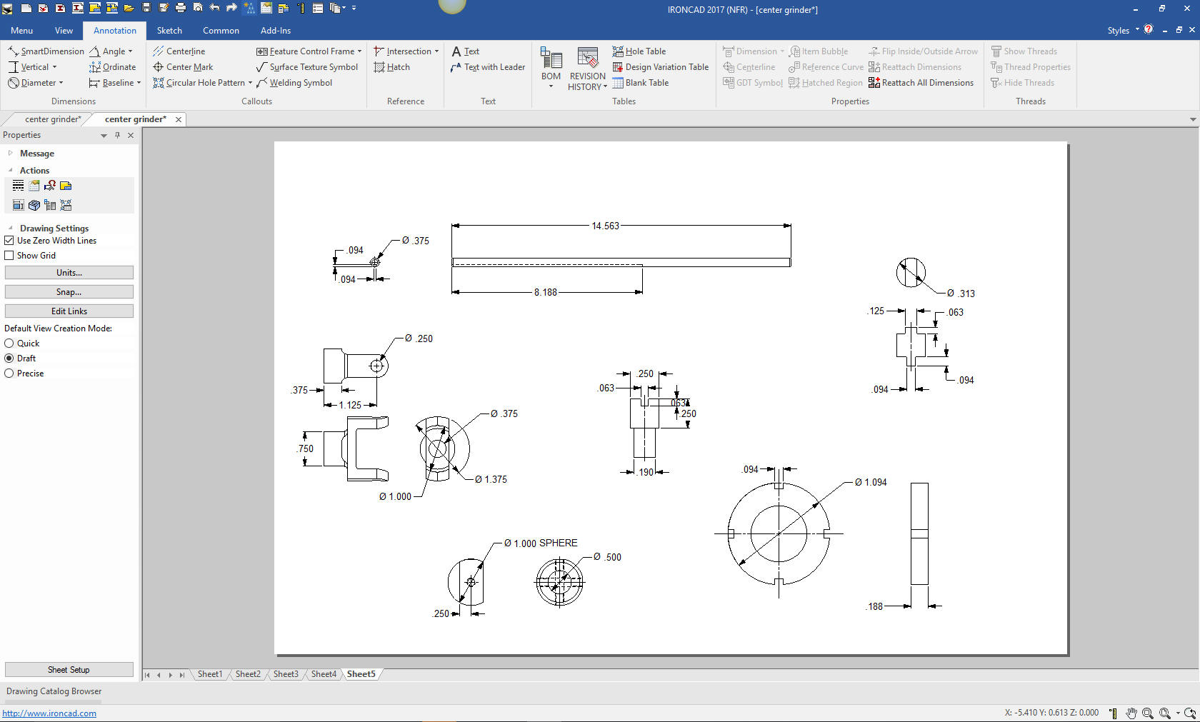
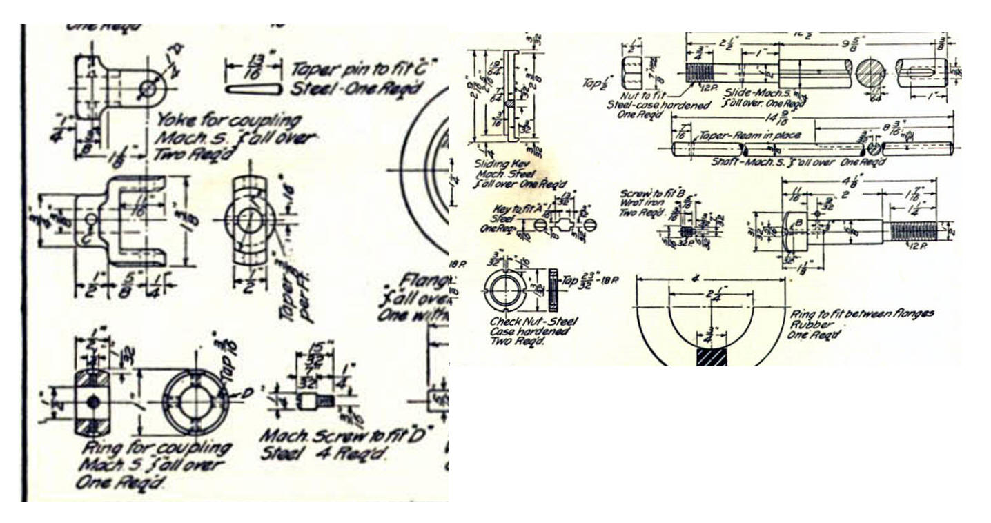
Here
is the original. I did add some dims that were not defined.
Now for lesson Five:
3D Modeling Techniques IronCAD Lesson
Five
If you would like
to try IronCAD, please download for a 30 day evaluation.
For more information or to download IronCAD
Give me a call if you have any
questions. I can set up a skype or go to meeting to show this part
or answer any of your questions on the operation of IronCAD. It
truly is the very best conceptual 3D CAD system.
TECH-NET Engineering Services!
We sell and
support IronCAD and ZW3D Products and
provide engineering
services throughout the USA and Canada!
Why TECH-NET Sells IronCAD and ZW3D
If you are interested in adding professional
hybrid modeling capabilities or looking for a new solution to
increase your productivity, take some time to download a fully
functional 30 day evaluation and play with these packages. Feel free
to give me a call if you have any questions or would like an on-line
presentation.
|