Home


Leverage Your Engineering Data Series 

Be sure to read our other articles:

Leverage Your Engineering Data throughout your Organization!

Leverage Your Engineering Data - Sales, Publication and Marketing

Simplifying Your Design Process


Image result for manufacturing

Checking, Design Review, Manufacturing and Data Extraction

Engineering’s "ONLY" purpose is to make sure that manufacturing gets all the information in a complete, concise and unambiguous format to manufacture our parts. With the introduction of 3D CAD that world changed. I will go through this process to see how we are now getting the data to manufacturing and how manufacturing can now access this data and utilize it more effectively.

Engineering’s only purpose is the delivery of concise, 
complete and unambiguous documentation to manufacturing.

Drawings

In the past there was the only one way we conveyed the information. It included everything necessary to create the parts and it also served as the inspection document. The drawing would be checked by the checker and when he/she signed it, it would be sent to the different engineering departments for review and signatures. They then were sent to Document Control, recorded and delivered as blue prints or microfiche to easily accessible central locations. Today it is much different, in fact, it is outright confusing. Just look at the hoops we are now jumping through to equal the information that was included on one document.

To Draw or Not to Draw?

The Death of the Drawing

The Death of the Draftsman

PMI (Part Manufacturing Information)

Today we have the 3D solid model. We still need to convey the information. Most companies still make a complete drawing. But some want to short cut this step and only provide the mating features and GD&T information allowing the non-mating features a standard profile tolerance. The solution is to put all the GD&T data and notes in a 3D view format, then demand that you have the special software to view this PMI data. This concept has caused some real problems for companies that use outside suppliers. There also seems to be a problem keeping track of this data. It seems that PDM (Part Data Management) and PLM (Product Lifecycle Management) is becoming more important than designing the parts. In the past this was easily done by the Document Control department, now it seems like this is being done by engineering with PLM.

The native CAD file cannot be used as
a standard engineering deliverable!

PMI vs AID (Advanced Information Document)

The problem is that the part doesn’t have all the relative information. So if you get a STEP or even the native file, only the file name defines the number, title and revision information. Once it gets imported that information is gone. This problem has created the need for 3rd party validation and compare programs. Well, I have an incredibly obvious simple solution so all part information is contained in the part file no matter what translation format is used. 

The Embedded Title Block! A PLM Solution!

Other related articles.

Why MBE/MBD/PMI Will FAIL

Why MBE/MBD/PMI Will Fail Part II

Free PMI Importer?

Redefining 2D/3D

The Worst to Best CAD System and Why

The Secret of Part Numbers

Parts List or BOM?

Take a look at this concept. INOVATE is the tool I am using here but I am sure all of the major programs can do this. The part information can be put in a webpage (Onshape). The part comes with enough pertinent information for anyone to make sure they have the latest version. Of course this is mostly for those companies that have many outside suppliers. The data could include the following and embossed or engraved in the part.

Part Name:
Part Number:
Revision:
Website:
Phone:

Since I started my engineering career at Boeing in 1965, I know a bit about how the drawings were done and distributed. In the beginning we worked with blue prints. Yes actually they were white on blue. We had blue print counters throughout the plant. Then I left the industry and came back in 1977, now there were microfiche, we could now get all of our drawings on a card and print the drawing and parts lists. I could take hours and hours to research the configuration we were looking for.

Website: If there was a webpage for each part and assembly, where you can see the latest 3D model, revisions and status of the part and download the part or assembly with permission. Outside suppliers could log-on to get the necessary data and be on a special list to be notified in case the part changes. With a standard process with a template it could easily be implemented for any size company.


Update: Onshape now offers the above concept today.
Update on the update: GrabCAD Workbench is almost there and it's free!

Cloud Based Engineering Document Control

Onshape and now GrabCAD are by far the most exciting developments that has been introduced to the CAD industry. Today you can have a standard deliverable with the latest information directly accessible to other engineering personnel, purchasing, marketing, document control, manufacturing, tech pubs, etc. You could have non-engineering personnel maintaining this information, let engineers do their work.

Onshape! A View from the Clouds

Things have changed with Onshape, here is an update on what Onshape now offers. It still offers incredible document control just a bit limited. It could actually become the "The Virtual Blue Print Counter" if the industry was willing to standardize on this process, eliminating the need for the myriad of complex nonstandard PLM systems. It would make MBE and PMI obsolete before it even gets started.

Update: With GrabCAD Workbench we are almost to standard engineering document control. We can eliminate the PLM system completely and make engineering more simple than it was in the past. Very few are around before CAD now. I was introduced to it in 1982 and am shocked how complicated the PLM gurus and major CAD companies have made it to lock companies into their system. Today, most companies are locked into the CAD system. This situation alone has stopped any advancement in 3D CAD. IronCAD is miles above any of the current Pro/e clones.

We could cut engineering design time, increase engineering quality, standardize engineering documentation today, with very little process changes, even with the existing CAD software. With an introduction of Hybrid CAD modeling which would standardize the 3D model we could save much, much more time with increased interoperability in both the engineering and manufacturing process. It is time to review our complete engineering/manufacturing process. It is time for engineering to be put back in control.

Onshape! The Party is over!

Here are a few examples of having a part mark on the part itself with this imported Autodesk Inventor Arbor Press assembly. You would put in on an easily modifiable surface. INOVATE makes this easy. You just drag the base text from the catalog, edit it, size it with handles and subtract or add. You see can how the text can be sized below. 


Most CAD and CAM systems can easily modify the part to eliminate the part mark to have a clean machineable surface. This is where a history based system has an edge on direct editing. You can just suppress the covering extrusion. With direct editing only products, you would have to have two parts. Luckily INOVATE has both History/Feature based and direct editing functionality integrated in the program.


For assemblies you can have large separate part with the same information.

Checking 

Checking seems to becoming a lost art. In the past, the checker would go through every dimension of the drawing marking it red, if incorrect, highlight yellow, if correct. Old time drafters said many times “That guy bled all over my drawing”. You quickly learned form, fit and function from every drawing you did. Many of us soon became design drafters and many even became the dreaded “CHECKER”, sometimes as a field commission.

Today with the focus on less drawings. How are we checking our parts? Most of the drawing checking was making sure the drawing was complete and defined the part. But much attention was paid to whether the part could be made or be made a better way.

With INOVATE, the checker could bring in each part and assemble and review the parts and assembly. With IRONCAD he could dimension the part to verify all the parts fit and would function correctly. INOVATE and IRONCAD are the easiest CAD product to learn how to manipulate parts and assemblies since you can work in one model.

Does checking take time? Of course, but it is much less costly to find errors up front then down the road where it cost thousands of dollars and much worse, sliding schedules. It is truly optimistic to think that design is correct without checking. Remember "Murphy" is just waiting for these moments!

Design Review 

An engineering manager can have design reviews without having the the complex native CAD software on his computer. Using gotomeeting sessions, you can easily prepare for and present the project and save it for reference. With IRONCAD an engineer or drafter can easily provide simple drawings showing the changes or a new concept and even has the ability to edit the part or create new parts. No need for constraints. The complete assembly is in one file with an external drawing file that can create multiple drawings of any of the parts or assemblies in the file.

Here is an easy modification:


We are going to rotate the motor and revise the tube.


Here is an easy drawing of the change. No constraints, no modification of any released parts. The complete assembly in one file where all of the attendees can have and do a variety of concepts.

Manufacturing

Many times your outside suppliers do not have your software. They can hardly afford to have a copy of very expensive programs like Creo (Pro/E), Siemens NX, Catia, Solidwork, Inventor, etc. Not only are they expensive, but most have a very complex interface and long learning curves. Designer, engineers or drafting checker are not the only people that needs to review the design. We have manufacturing, material, and stress engineers that need access to the design.

Quoting Tools: CAD Dimensioning Another Band-Aid for MBE!

So what do they do? With INOVATE they can have a very inexpensive translator to import the above native programs. But with INOVATE you can edit the models. Like removing features that are in the way during the machining process. Most of the features can be converted to recognizable features that can be suppressed to create a part for rough machining and then again with all the features available to finish the job. You can remove fillets or any other feature that will get in your way. Take a look below at how this works for the CNC programmer.

An imported Solidworks pump assembly.

We want to machine the cover. We can select the part in the tree or on the screen and hide the unselected.

Now we want to remove the holes, but we do not want to delete them because we are going need them later. We convert the holes to features and suppress them. Notice we can select all of the holes.


Now we can remove the pockets. First we make a sketch and then extrude. Then feature recognize the top filet and suppress. We now have the part ready for machining and can be exported to your CNC software in its favorite  import format.


This is the beauty of INOVATE. You have both history and direct editing integrated in the product, in fact, it is the only CAD package that does. Update: Universal CAD Compatibility is Not Here!! If you had done this in a direct editing only package you would have had to save 3 separate parts. This is a very easy procedure with a very short learning curve. Remember we are in the assembly. No external parts to worry about. Much less part data management to be concerned with. Now all we have to do to return to the original part is to suppress or un-suppress the affected features. Look on the left in the history tree or scene browser you can see the added features.

DATA EXTRACTION

Stereolithography is now the standard format for FEA, 3D printing or reverse engineering. INOVATE like most other systems can easily generate them. But since INOVATE started out as a graphics design package you can review stl’s as part of your renderings. Below we will create a stl from the cover.

Now we can import the stl or any other stl and use it for rendering with our solid parts. We can even change the colors.

We know you are heavily invested in your current system. Many of you have not experienced any other systems to even know that there is a better or more productive solution. That is why I include so many renderings showing you the capabilities. What we are promoting here is that IRONCAD/INOVATE are incredible enhancement products for your existing system. Products like Creo (Pro/E), Siemens NX and Inventor have direct editing modules that can import and modify virtually any solid and can now be completely compatible with other system. Even Solidworks offers a limited feature recognition. Catia 5 is the only system the does not offer any form of direct editing. But these systems are designed for an experienced user and require a long learning curve. For a manufacturing supplier it is unrealistic to think you could utilize all of the systems even if you could afford them. The engineering and manufacturing world is in transition. I am here to hurry it up by offering an incredible cost and time saving solution.

IRONCAD/INOVATE are the most sophisticated solid modeling programs available. You step out of the sketch dependent programs yet have all the history functionality available. You can directly edit any feature. You can drag and drop features, parts and assemblies into the works space. As I have worked with Inventor and Solidworks I feel like I am working on some archaic CAD system with the most constraining (no pun intended) environment.

What are you using now to utilize the engineering data, or do you even know this capability is available? To implement this in your current system you would need expensive modules or a separate package for each job. This is most cost effect solution and so easy to implement. Please attend our webinar or if you can’t make it give me a call and I can give you a presentation of these great capabilities.

You can experience this today!

For more information or to download IronCAD

Download the very complete “Getting Started Guide” 

It is easy to load and get up to speed. It includes all the translators so you can get started seeing the advantages of implementing the power of INOVATE or IRONCAD CONNECTIONS. You can directly access your existing engineering data. Take some time to get the other departments involved. This truly is the solution to make each person in the company access to all the engineering data and in the know.

Take a look at the "Product Comparison" 


One more important face. If you are an Autodesk or PTC user you must not move to the subscription only. Stay with the latest version before the move or start moving to another system. Not because of the continuing costs but Autodesk and PTC can hold your engineering data or IP hostage. This is a very dangerous situation for any manufacturing company. It is also another good reason to get your engineering documentation out of the native CAD system.

You are Not Stuck with Autodesk or PTC Subscriptions

TECH-NET Engineering Services!

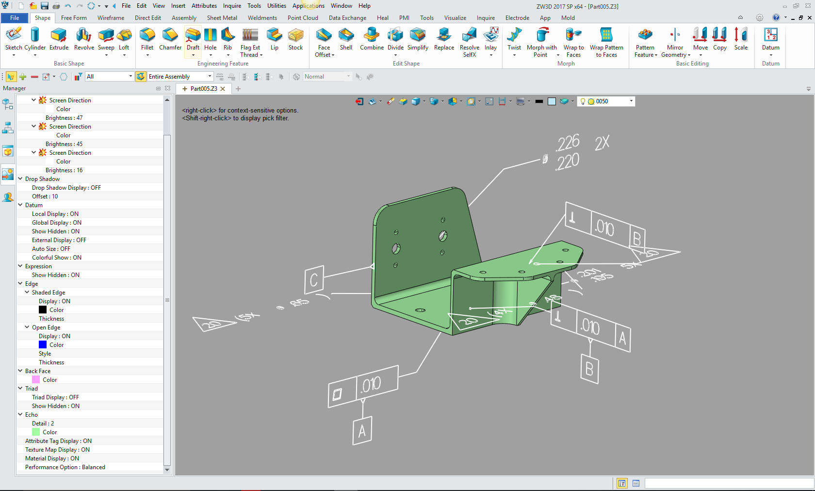
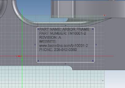
We sell and support IronCAD and ZW3D Products
and provide engineering services throughout the USA and Canada!

Why TECH-NET Sells IronCAD and ZW3D


If you are interested in adding professional hybrid modeling capabilities or looking for a new solution to increase your productivity, take some time to download a fully functional 30 day evaluation and play with these packages. Feel free to give me a call if you have any questions or would like an on-line presentation.


If you would like more information or to download ZW3D or IronCAD

Joe Brouwer
206-842-0360
 
HOME | ABOUT | PRODUCTS | SEMINARS | TRAINING | TECH-NET NEWS
TECH-NET ASSOCIATES | RENDERING OF THE MONTH | CAD•CAM SERVICES
HARDWARE | TECH TIPS | EMPLOYMENT | CONTACT