|
"The Total Purpose of Engineering is to deliver complete, concise and unambiguous documentation to manufacturing."
Yesterday, it was a Single Manual Drawing!
Not to be confused with today's
similar, but much different, Wrongly all drawing like documents are lumped into one moniker "2D Drawing"
Now let's see how today's engineering system does this! PLM is the Single Reason Engineering is in Chaos Today! | |
|
Update: 1/2/2018
I now realize the basic problem with PLM is that it is top down design. When any engineering or drafting professional knows the engineering process is bottom up. Document Control is based on well maintained (not by engineering) central archived files. The PLM guru has never studied the standard document control system of the past. Quite simple!
The problem is a the standard engineering documentation format. I believe it should be outside of the native CAD system. Delivered as a 3D model in a native and/or neutral format and a fully detailed AID or a drawing if not based on a 3D model. Too simple???
Engineering Documentation - A Primer for the PLM Guru!
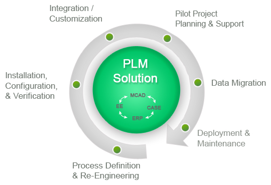
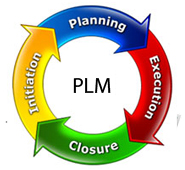
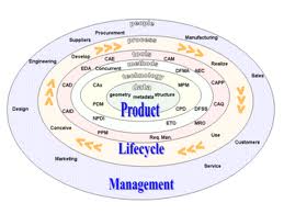
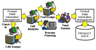
Before we get started I have to show you a few PLM images. It has been a while since I posted this article and decided, since the original image (which was the only one I found at the time and shown below) was a bit funky I searched for a new one!! Go ahead Google "plm product lifecycle management" I was shocked at the many different images describing PLM. This actually makes my point. This is hardly a viable standard that we can base our engineering and document control. These are just a few. What is this some kind of joke? Don't any of these folks realize we need a standard? What is the matter with engineering management, could they possibly be this ignorant or could it be they that they being manipulated by a vested interest?
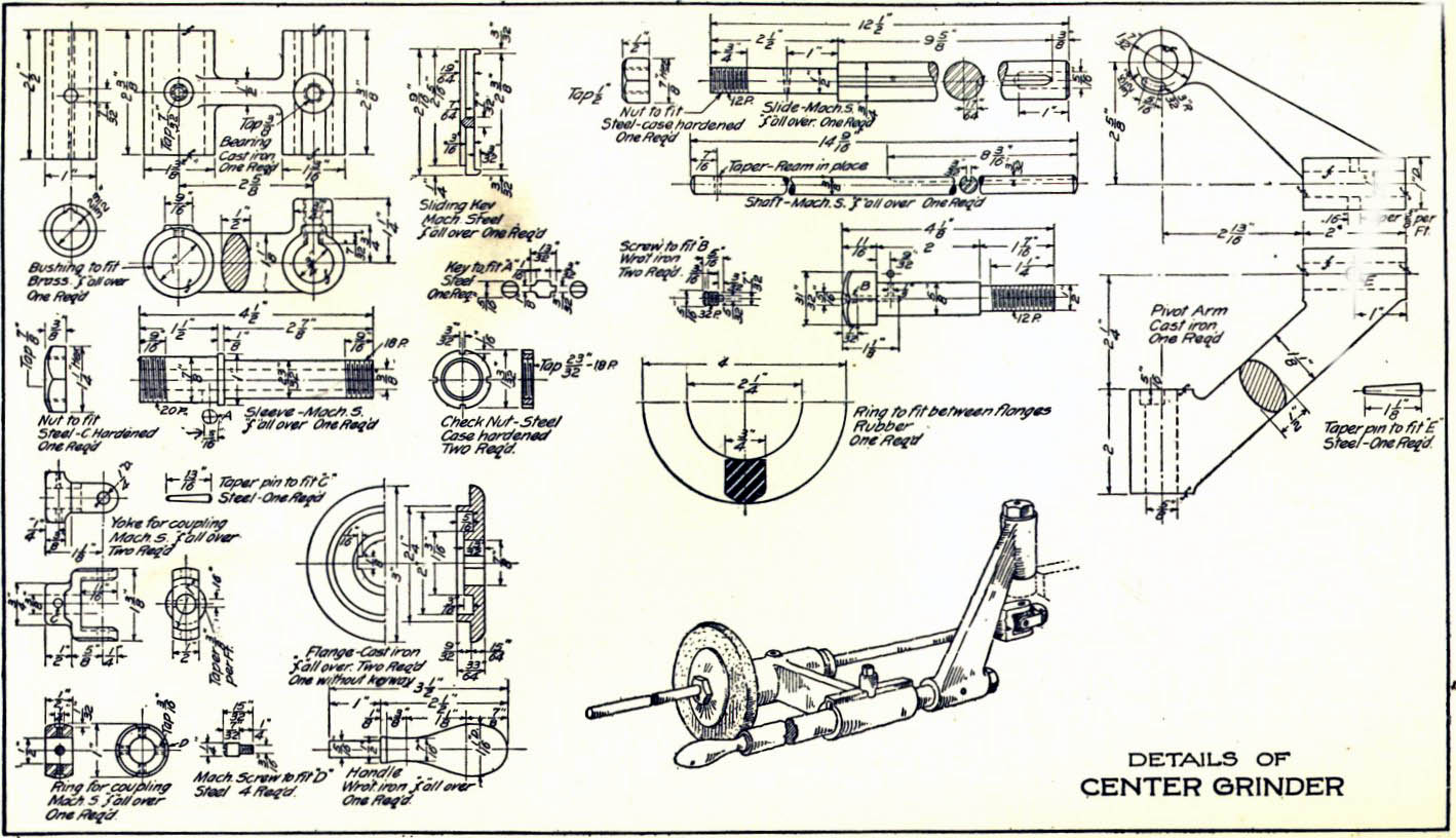
I have said this many times: "I believe that engineering and manufacturing was much more cost effective prior to 3D CAD when the part and assembly authority was the standard manual drawing."
The Space Between Engineering and Manufacturing
Engineering Documentation Today!
PLM (PRODUCT LIFECYCLE MANAGEMENT) AND PDM (PRODUCT DATA MANAGEMENT) DEFINED!
PLM (PRODUCT LIFECYCLE
MANAGEMENT)
What is PLM?
A bit more on the failure of PLM The Worst to Best CAD System and Why!
Who needs PLM?
It is not clearly defined who needs this, but from what I have read, it seems to be a solution for large multi-year design projects, designed and manufactured in different locations, with multiple suppliers and many concurrent designers. Actually, only the large companies can afford this failed experiment.
Catia, Siemens NX (was UG) and Creo (Pro/E) (High-end CAD), Solid Edge, Solidworks and Inventor each offer a unique solution based on their software. There are also a myriad of stand alone PLM products.
Don't believe me!!
Here are 139+ programs that claim to be PLM.
Product Lifecycle Management Software
"Find the best Product Lifecycle Management Software for your business. Compare product reviews and features to build your list."
Can you imaging giving an employee this task from this list?
What was done before PLM. Oh yes we had manual drawings and on these single manual drawings had the parts list, specifications and all the data necessary to manufacture the product. Yes, Joe is getting back on his soapbox. The 747 is a product that fits the definition of a product that would need PLM. The Airbus A-380 was a comparable product that used PLM in the design and manufacture. We have heard of the stories of errors in engineering and manufacturing on that project and now there are similar stories being told on some current projects, these errors don't cost millions, they cost billions in missed schedules and rejected parts. The problem: Using two totally incompatible versions of the same CAD product, Catia 4 and 5. PLM came into effect when the high-end 3D CAD packages moved to the PC. I was introduced to it by my confused Boeing suppliers in 2000. That is 19 years. I am shocked that I seem to be the only one that can see PLM/MBE/PMI as a completely unworkable system! Why? It can't be standardized!! Those in charge, the major CAD vendors, have a vested interest in keeping it this way. Think it through! How much would you save if we all had one standard engineering process? The level of interoperability would be amazing. The documentation would be readily available and easily archived. If you are in engineering management and you can see this costly turmoil. Please read some of my articles. It is an accumulation of 53 years in engineering, of which, 36 have been in using, selling, supporting and training 3D CAD.
To manage a PLM system you need a large force of IT folks, hmmm, I wonder who is behind this conspiracy. Today, Boeing is losing 25 million on each 787 sold. Can we blame PLM? I will tell you as one that supplied many of the Boeing suppliers with 3D CAD it is a big part of it. Boeing is making its suppliers jump through hoop after hoop trying to make their PLM/MBD system work.
Compare and Validation Programs? Band-Aids for Self Inflicted Wounds!
I have again been approached by a supplier to
provide drawings of solid parts from Boeing.
The vendor is in a bit of a donnybrook with Boeing,
trying to get clear definition of the parts.
Boeing sees no problems in the 3D MBD, yes (3D Model
Based Definition) and PMI (Product Manufacturing Information) that they are
providing. This has been an ongoing struggle for this company since the
project started a couple of years ago.
They even have a compatible Catia 5 station, of course, no one is
trained (6 to 12-month learning curve) on the software and they use it to
only get the part models to IronCAD or ZW3D.
In the past, they have had a hard time getting me the PMI, which is
basically annotation GD&T in 3D space.
This is not easy to view, depending on the complexity of the part, in
fact, it can be a horror show and impossible to interpret.
Good afternoon Joe, I read through several of your
articles/blogs and found it to be very interesting. For our
company, I’m asking if you could offer a suggestion or better
solution to our requirements. We currently have a seat of
Catia V5 to look at .catpart files for quote and I also use it to
make paper drawings from the models of parts that we currently make.
787 parts mainly. This is expensive software as you know, and
it’s what were led to believe was the best solution for moving
forward in the MBD environment. Our shop prefers parts lists
and paper drawings. Maybe it’s antiquated thinking,
but it still works best for us. Is ZW3D software a good
alternative for getting the required information from a Catia V5
model to make a paper drawing and parts list? Sometimes we do
get an EPL or BEPL with the notes, flag notes, etc extracted out
already, but not always. I’m sure you all well aware of what I’m talking about and asking. We are a Boeing subcontractor but since being bought by the XXX group, we now do other aerospace work as well, Airbus, Bombardier, etc. Our parent company is based in France so I’m hoping a move away from Dassault won’t be frowned upon 😊 Any advice or help in a better direction would be much appreciated. It’s been some time but we used to buy Cadkey from you years ago.He is not the only one having problems with Boeing PMI.
Take a look how PMI looks in Redefining 2D/3D.
Hybrid Modeling and PLM
With Siemens NX (UG) and Pro/E bringing out hybrid modeling modules incorporated into their software, they will be able to import models into the CAD package and use their PLM to maintain the parts and assembles and even modify them. So now it will not matter what package the parts are created. This is truly the next step in CAD compatibility. All packages with have this modeling capability or they will not be in business. I still believe that ZW3D offers the best of both worlds. ZW3D is the best overall hybrid modeler since it incorporates 2D/3D wireframe, Surfaces and solids in one easy to use 3D space, and is the only fully functional and most affordable Catia translator/modeler and includes PMI.
Update 8-15-16:
Sadly, this function is not readily available in the design process of the popular packages and has not delivered the potential to standardize 3D CAD modeling.
There is no Universal 3D CAD today!
So are you ready for PLM?
PDM (PRODUCT DATA MANAGEMENT)
What is PDM?
Product data management is a category of computer software used to control data related to products. PDM creates and manages relations between sets of data that define a product, and store those relationships in a database. It is an important tool in product lifecycle management.
In truth, PDM should be data
management inside the CAD
system. Only used by trained
personnel. This should deliver
the final documentation to
Document Control.
Document Control should not operate in the
native CAD system. It should be a
external to the CAD system and
only maintain the documentation.
Sadly, I don't think any of
these folks know what they are
doing.
I have devised a much better "Engineerign Document Control System" than PLM. PLM has so many Band-Aids on top of Band-Aids with an incredible lack of applicable knowledge of those that are involved assuring it can never be salvaged. Actually PLM should not be involved with engineering at all. So what do we do?
If PLM should exist at all it
should be only dealing
In the article below I envision a Web page deliverable for each part or assembly. This would be done by a separate Document Control Group, utilizing a standard release package or bundle from engineering. This is nothing more that modifying a template. I, of course, never had the resources to bring this to fruition.
But today we have that solution.
The Embedded Title Block - A PLM Solution!
Onshape offers that concept and more.
Onshape
is by far the most exciting
developments that has been
introduced to the CAD industry.
Today you can have a standard
deliverable with the latest
information directly accessible
to other engineering personnel,
purchasing, marketing,
manufacturing, tech pubs, etc.
and can easily be handle by an
outside "Document Control Group"
You could have non-engineering
personnel maintaining this
information, let engineers do
their work. You can include a
variety of solid model formats
including the native file, all
detailed documentation in PDF or
any other documents or images.
Standard Cloud Based Engineering Document Control
Update: 2-4-15
Product Data Management is such a misnomer. As a Senior Design Draftsman we never called our drawings data. That is an InfoTech term. We were creating documents which at Boeing were managed by the Document Control Group. This misunderstanding of what we produce and deliver is what has created the convoluted PLM and MBD and its ugly stepchild the infamous PMI. If the powers to be realized it should be "Part Document Management" we could probably straighten this mess out. The basic building block of any "Product" is the individual parts.
There is now no effective engineering management!
Those that have never designed a part should not be telling engineering how to maintain our assemblies and our revision process. Realize all 3D CAD did was add the 3D model. Effective engineering management has to get back in control of engineering, how they let PLM get in charge shows an incredible lack of understanding of the standard process of the past. We should be delivering "standard" documentation and pass it to a group that maintains and distributes the documents outside of engineering.
There are two data streams in today's engineering process, native CAD and the standard engineering documentation for the outside world. The CAD systems are very difficult to learn and do not lend to casual use. We need a standard document, including the 3D CAD information, packaged in such a way that can be easily duplicated with no special software or training. Today, PLM and MBD have created an industry of 3rd party products that are required to view the native CAD PMI deliverable. Sadly, there is not enough applicable knowledge to straighten this process out. They are adding Band-Aid on top of Band-Aid trying to make it work.
Quoting Tools: CAD Dimensioning Another Band-Aid for MBE!
Martin Eigner, a professor at the University of Kaiserslautern, Germany (and also an advisor to PLM developer Aras), says
”the complete, fully functional PLM system does not yet exist in the material world” - and it may never achieve a flawless implementation, not even in the most advanced industries like automotive or aerospace."
Here is a comment from the PLM PDM CAD Network on Linkedin.
Topic: E(E):
One Revision to Rule
Them All
Here
Look at this comment. A snap shot? The drawing was the complete definition of the part. For the life of me, I do not know what other information is needed? Can you see the complete lack of understand of the engineering/manufacturing system?
The Space Between Engineering and Manufacturing
B
Update 2-4-19
After a conversation with a user of the major software package I know understand a bit more of the problem with keeping the parts/assemblies alive. They reside in an associative environment due the the separate part, assembly and drawings.
So, what "HAS" gone wrong with Engineering? Part III We haven't made a Drawing Since 3D CAD was Introduced!
The Native 3D CAD file
cannot be used
Who needs Part Document Management?
Most of my clients are already using some form of PDM even if it is just in folders in Windows Explorer. And most of these clients are still smart enough to use AIDs. The PDF's generated from the AID of the part or assembly is used for quoting, scheduling, manufacturing, procuring, checking, reviewing, planning, refining, cost effect evaluation, new product definition, etc. This PDF can include all the data necessary to completely design this part or assembly. No need to have a special viewer since the Adobe reader is available to all. You can even include a part to view in 3D. The non-engineering folk really don't need the 3DMBD (3D Model Based Definition), they truly only need a drawing and the specifications.
Here is an article that adds a 3rd party solution for a self-created problem.
Quoting Tools: CAD Dimensioning Another Band-Aid for MBE!
In my viewpoint this is the only
thing that is necessary to be
delivered outside the design
engineering departments.
Yes, we do need to also deliver
a 3D model to manufacturing that
should match the AID (2D
drawing). Yes, this puts a
lot of responsibility on the
design engineering group to make
sure the AIDs (2D drawings) are
kept current, but this is no
different from the past.
Many of the manual drawings
started out as assembly layouts
(non-standard drawings), from
which the manual drawings were
created. But for some reason,
currently this is
considered very time consuming
expense until the parts start
coming in wrong or mistakes are
caught by manufacturing.
Project cost over runs, delays,
redesign, etc. are the result of
not measuring twice and cutting
once and, of course, ignoring
Murphy!
PDM Advantages:
The Drawing:
In the past the drawing was the total PDM package. It is, as if it was a mystery, how we made products. We did all the above with one document.
We had signature blocks:
Drawn: The name of the drafter/designer Engineer: The responsible Engineer Stress: The stress engineer Mfg: The manufacturing Engineer Mgr: The responsible Engineering manager
PL (BOM) All material and size and parts if assembly. Notes All specs for the materials or Assembly rigging instructions. Rev Block Kept track of all revision to the part or assembly.
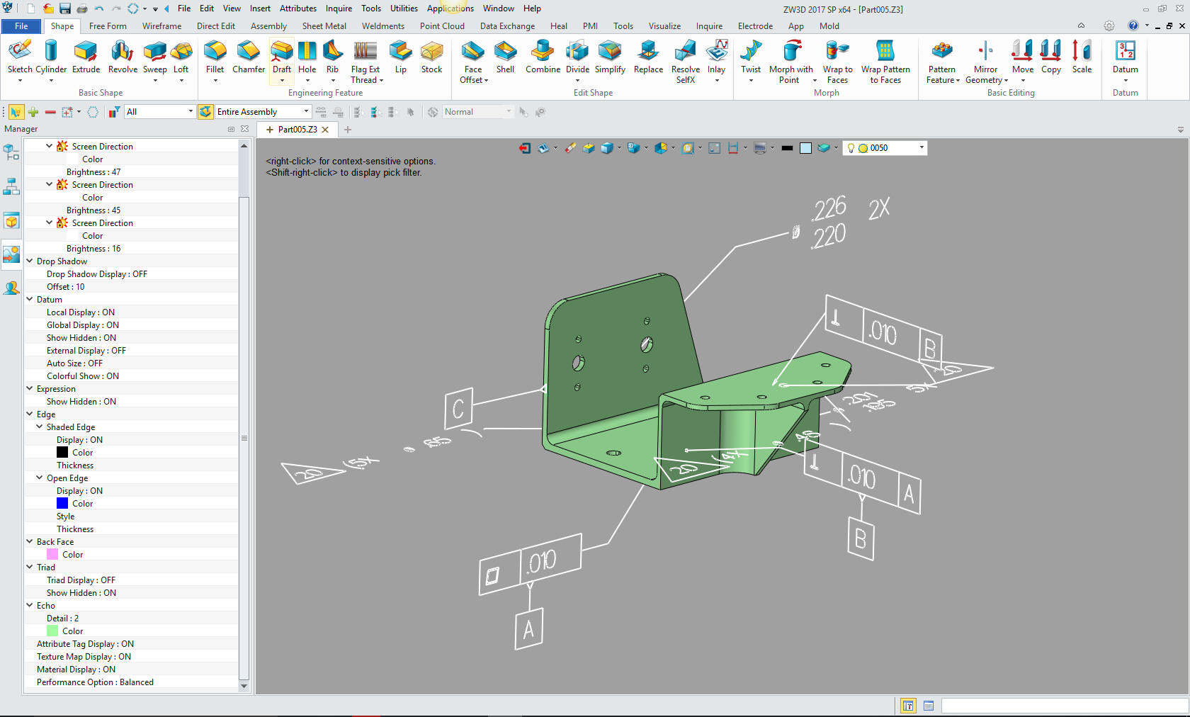
Yes one document, compare that to now. You have to have a special software to view the PMI. 3D PMI had dimensions all over, to the point where they are too confusing to review. Quickly realizing fully dimensioning parts in 3D was not effective. They kept reducing the dimensional requirements to just a bit of bastardized GD&T. The features that are covered by the profile tolerance are not dimensioned, leaving them to really be overlooked by the designer. I am now seeing parts that could not have gone thru all the above checks. Many parts could not be manufactured and many are not fitting at assembly. There are no short cuts to complete engineering procedure.
Why MBE/MBD/PMI Will Fail Part II
PTC Creo Totally Misunderstands MBD
Solidworks Totally Misunderstands MBD
Enter the 3D model:
Many think the 3D model does everything. Sad to say it really doesn't. Yes, we can use the model for new products. But to manufacture the part, it has to be documented. Many of the parts I have looked at have been created by CAD jockeys and from the looks of them not reviewed for manufacturability. These parts have been rejected time and time again by the suppliers, or many times they have been done to only be not to fit in the assembly.
Engineering is a time consuming endeavor. It has to be done as correctly as it can be done. It has to have checks, and rechecks because "MURPHY'S LAW" is in full effect. I know this will fall on deaf ears. But if you supply the AID and the 3D model in the same package that is verified by the responsible design group you can be assured that the correct part is being manufactured. From the looks of the results the 3D model is becoming more of a hindrance then an asset, at least in the current form of delivery.
PMI vs AID (Associated Information Document)
The ADCN (Advaced Drawing
Change Notice) vs MBE
We have an incredible solution for those of you that would like to:
This allows you to have many different departments easy access to you engineering data, for Data Translation, for the Casual User (Management Review), Publications and Marketing, Sales, Documentation, Design Review, Manufacturing, Checking, Data Extraction, Kinematics, Sheet Metal, Engineering, Easy Model Creation, out side suppliers. vendor compatibility, 3D pdf's, Rendering, Animations and more.
Now you know that anyone outside engineering could never use the Pro/E, Catia, NX, Solidworks, Inventor and other complex engineering programs to do their jobs. Even in supporting engineering departments the programs are much more than are required.
Imagine a CAD program where you could read your complete assembly into one file and view, manipulate and even edit the parts and assemblies.
We have products the fill that need:
The CAD product I use is IRONCAD/INOVATE. Are you tired of the sketch, sketch, constrain, constrain, painful way of CAD design? Take a look at the most sophisticated CAD solution available. The basis of engineering is creating parts and IRONCAD/INOVATE can just do it easier and faster. CAD does not have to be complicated. Give IRONCAD/INOVATE a try go to this link to download a 30 day fully functional evaluation, including all the translators.Download the very complete “Getting Started Guide” It is easy to load and get up to speed. It includes all the translators so you can get started seeing the advantages of implementing the power of INOVATE or IRONCAD. You can directly access your existing engineering data. Take some time to get the other departments involved. This truly is the solution to make each person in the company access to all the engineering data and in the know.
ZW3D Increase your productivity 2x to 3x with Streamlined Sketching and Feature Based Modeling!
TECH-NET Engineering Services!
We sell and support IronCAD and ZW3D Products and If you are interested in adding professional hybrid modeling capabilities or looking for a new solution to increase your productivity, take some time to download a fully functional 30 day evaluation and play with these packages. Feel free to give me a call if you have any questions or would like an on-line presentation. Joe Brouwer 206-842-0360
|


TECH-NET ASSOCIATES | RENDERING OF THE MONTH | CAD•CAM SERVICES
HARDWARE | TECH TIPS | EMPLOYMENT | CONTACT