 |
|
Engineering documentation is the language of Engineering. Engineering's total purpose is to make available concise, complete and unambiguous documentation to manufacturing. I am probably the one of the few that know this history. This is not just Boeing’s history but probably the history of all the very large manufacturing companies. Boeing literally wrote the book on engineering documentation with the many company standards that were applied and monitored by the incredible drafting group. First, I was a born draftsman! When I was in the
fourth grade I read about hydraulics and wondered who worked with this. I
found it was engineers and draftsman. Drafting? What the heck is that. I took a look and started
buying small drafting kits. When I got to high school I sign up for drafting
class. Sadly, they put me in a round robin course that included a quarter of
drafting, metal shop, wood shop and radio shop. Radio Shop, good gawd
electronics is still FM to me. I never followed up on it. It seemed like the
drafting class was always full. Not much student guidance in those days. I
was a bit of a handful anyway. I had two parents with personal problems that did not
allow them to even realize they were supposed to raise children, so my
sisters and I raised ourselves. I got out of high school with no plans and
no job! My Miracle There were quite a few of us in this situation, not
interested in college with no profession. I had
already come back from a trip to California (Where Washington State boys
went for adventure). I worked a bit down there and started college. But I
was lonely and came home. Suddenly, my friends and I got wind of a program
sponsored by Boeing for Draftsman and Electronics assemblers. I had an
aptitude test that show my spatial skills were off the charts and I got
accepted.
This
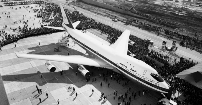
It was 1965, when I stepped to my first drafting
board. Worked in the Triple 7 Passenger Accommodations, nope not 777, but the 707, 727 and 737, soon I was transferred to the 747 Escape Slides group! I was not happy making layouts for the new engineers that were getting paid more, so I headed out as a contract engineer in 1968. At that time all the drawings were done on mylar!
That is a plastic film using plastic lead.
We would do the drawings, review them, check them and release them to document
control. They would create blueprints and stock the blueprint counters manned
by young woman throughout the buildings. The originals were stored in a
vault. Yes, an actual vault. Boeing knew the value of the engineering
documentation. Every company
I worked for handled the documentation the same way. I would walk on the job and would be
productive that day due to the common engineering standard. Boeing 1975
Ten years and not much had changed. The blueprint girls were gone, and the drawings were
on microfiche. I was at Boeing for about 5 months, contract
engineering was in my blood, back on the contract engineer (jobshop) trail.
The standard engineering document at that time! The standard engineering drawing was honed to perfection after centuries. The Manual Drawing - The Perfect Engineering Document ENTER 3D CAD
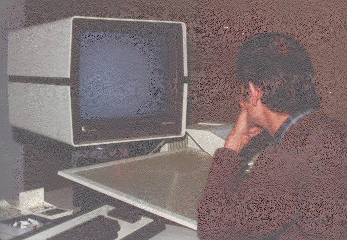
I was lucky to be allowed to learn Computervision
CADDS 4 after work. After a couple of weeks I was put on the system and became a 3D CAD draftsman.
Why did these companies move to 3D CAD? You can not look at 3D then with today’s 3D eyes. The systems were 3D wireframe. The selling point of 3D CAD systems that cost millions was faster documentation. The model was only used in the creation of the document. They were made by defining views from the 3D model in a documentation module and detailed and annotated per the current drawing standard. They were plotted on vellum and sent to document control where they would be handled like manual drawings. They were exactly like manual drawings except the lettering was perfect. But these were not drawings, there
was no drawing done at all. Computer Generated Engineering Document Sadly, they continued to call these CGEDs (My acronym)
drawings, which caused a mass of confusion in the future. More on this later.
After 10 months I was a seasoned user. Being the
quintessential jobshopper I sent out my resume and found that Computervision
CADDS 4 users were in huge demand. I took a job at Comdial in
Charlottesville, VA! My rate went from $20.00 to $35.00!! Not only that I
did something unheard of, I jumped engineering disciplines from
aerospace to plastics. I soon found that 3D CAD was flourishing in these two
disciplines. I went from Comdial to Solar Turbine, back to
Williams and then back to Boeing with a week stop off at Goodyear in Akron. BOEING 1986 I took a contract at Boeing in 747 Flight Deck in
Everett, WA. It was a board job and the only reason I took it was to get back to my
family and my newborn son. All large manufacturing firms skipped electronic
drafting and moved directly to 3D CAD. Boeing gave Computervision a try,
they had a CADDS 3 system. But Computervision was developing a poor
reputation with its mini-mainframe and Boeing started looking at other
systems. They look to the Dassault product, Catia. It ran on IBM computers.
No one was fired for buying IBM. Catia 2, like CADDS 4 was wireframe. It seemed like
there was no documentation being created out of Catia 2 that I can remember. They seem to be
creating section lofts for us to use for our manual drawing. If they did
create documentation, I don’t remember seeing it. They only let direct prima
donna draftsman on Catia. Again the engineering world was about to change. I was whining about being a “3D CAD” design draftsman
and the horror of being back on the board. One other draftsman said “Joe,
there is a PC based 3D CAD system on two Compaqs in the small office”. Hmm
PC based 3D CAD??? Interestingly, I was already familiar with the PC and
had played with Autocad on my IBM Luggable with a 5-inch amber screen. It was
a horror show. I did a fence for my back yard. I was a 3D CAD designer, and
this was a huge step backward. I jumped on the system and it was CADKEY! It was very
much like CADDS 4 but instead of using a dig pad it used a UGI. It had a
color monitor, CADDS 4 was monochrome, green on black. It was 3D wireframe
and within 2 weeks of lunch hours I talked the management into doing a test
project. Joe, I thought this was about Boeing documentation? Hold on I am almost there. We did the 747-400 first
observer workstation. This was the beginning of a two-person flight deck crew. I worked
with an engineer and the project went flawlessly. Boeing had the plotting in
place using the HP plotting file standard: HPGL. My CEGD (electronic documents)
were
plotted checked and released into the system just like a manual drawing.
We could get loft information from Catia via IGES. I am shocked how well both systems worked together at the time. Later I found that CADDDS 4 also worked with CADKEY with IGES. Soon we had every draftsman and board engineer on
CADKEY. I was the training and CADKEY manager and still doing
design work.
These were not drawing but CGED (Computer Generated Engineering Document)
which the Boeing Draftsmen fondly called “The Flatfile” Until 1987 the 3D model was only used to create these
CGED or
“Flatfiles”, again since they were plotted and released like manual drawings,
they were called drawings even though there was no drawing involved. 1986 to 1987 - Model/AID Documentation
The
Boeing Authorizing Engineering Document delivered were manual drawings or
CGED “Flat Files” from CADKEY or Catia 2 and delivered as
Prints
Enter 3D surfacing 1988 This was by far the biggest advancement in engineering and
3D CAD. With surfacing came CNC program software. It was interesting that they were released on the PC, programs like MasterCAM, SmartCAM, SurfCAD and many others. Where were the surfaces coming from? CADDS 4 and Catia were getting better at
creating usable surfaces delivered as IGES files. Pro/e was introduced right
on the cusp of this movement and could export the solid models as IGES surfaces. CADKEY had a 3rd
party surfacing program called FasfSURF and joined the high-end systems
providing IGES surface models. This was the surfacing manual from FastSURF! It was 3D in CADKEY and we could use them as actual examples. We sold hundreds of FastSURF as CNC and 3D printing was being widely introduced.
1995 Solid Modeling On the PC - CAD productivity Soared! Boeing and the industry documentation changed. Engineering documentation: Model/AID We now had the 3D model available for milling machines and sheet metal to use CNC programming. The CGED were much easier to create in the documentation module with introduction the solid model and hidden line removal, prior to this we would have to do the hidden line removal manually. A tedious chore. The CGED or “Flatfile” became what I have coined the AID
(Associative Information Document) since they were still calling anything
that looked like a drawing a drawing, or worse “The 2D drawing” as if there
can be another kind. Yes, Boeing and all of the large manufacturer were now
supplying the machine shops and sheet metal houses with 3D models in the form
of IGES to use as patterns and paper prints of the AIDs to define things
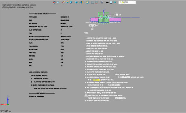
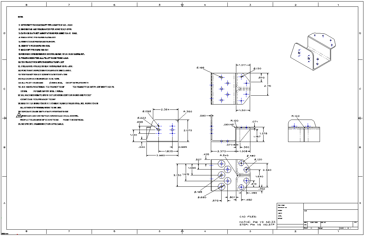
like material, finishes and tolerances. The AID was fully detailed and
annotated and could stand alone. This confused those that did not understand
the concept as they thought only the AID was being delivered. Truly this was
still misunderstood well into the next century. PTC Creo Totally Misunderstands MBD Solidworks Totally Misunderstands MBD
The Model/AID engineering documentation continued at Boing until the turn of the century. Most of the engineering world uses this concept today. MBE/MBD/PMI is very expensive to implement. The PDF closed the door on paper prints. After the introduction of the PDF around 1998 the
manual drawings and AID were delivered as PDFs
The Turn of
the Century! What Happened to CADKEY? Before we move to the next milestone. I would like to explain why Boeing did not select CADKEY as their primary CAD system. It was much more functional and than Catia 2/ 3 and even Catia 4 and wide spread with approximately 1500 seats. But it ran on a PC. BCS (Boeing Computer Services) were in charge of all computing and they didn't like the PC and any software that ran on it. They were losing control to those with layman PC skills. So they opted for the networked Catia, costing millions and stifling Boeings 3D CADs growth for 10 years. Boeing could have led the way with sophisticated direct edit modeling on the PC instead opting for Catia 5 that was a clone of the complex history based Pro/e paradigm 10 years later. CADKEY or Catia? Boeing’s Billion-Dollar 3D CAD Mistake! Enter Catia 5 and PLM
The engineering documentation world changed at Boeing
with the incredibly overly complex implementation of Dassault Catia 5 PLM, a
poorly designed Pro/e clone. The Worst to Best 3D MCAD Systems Expanded! This started Boeing engineering on a downward path. Boeing, was the greatest engineering/manufacturing
company on the planet they wrote the book on engineering documentation and handed
over all the engineering documentation responsibilities to Dassault Catia 5
PLM with
virtually no evaluation period. "Chaos is always the result of trying to reinvent the
wheel Boeing InfoTechs or IT (Old BCS) working with Dassault moved to PC based Catia 5 at the turn of the
century. Prior to that they used a Catia 4 on an IBM networked system. Prior to Catia 5 Boeing was sending IGES and STEP files along with a print of the AID. I am sure they never thought what the suppliers were using, which was PC Base CADKEY. TECH-NET supplied Boeing, all of their suppliers and many other industries with CADKEY in the NW. CADKEY was the only effective and compatible PC Based 3D CAD package at the time. The 1990's - 3D CAD/CAM Moves to the PC!! With the implementation of Catia 5 Boeing recommended
that all suppliers get a seat of Catia 5 to be compatible. Soon CADKEY and IronCAD included the ability to read
Catia 5 files. My customers were still using CADKEY or IronCAD to import the
native Catia 5 files by passing the Catia 5 seat that was used to satisfy
Boeing. The Moment Boeing Disconnected from the Proven Standards they Created I got a call from one of my Boeing suppliers and they told me that Boeing was not including the prints with the model and they were just sending the native model. They now had a new authorizing document! The 2000's - The Age of 3D CAD Un-Enlightenment! Enter MBE/MBD and the PMI The PLM folks were struggling keeping the 3D model
and the AID synchronized. MBE – Model Based Enterprise This was strange since we were sending the 3D model
with the AID since the late 1980’s with the introduction of surfaces and
CNC. But this new idea solved the two-file problem by
including all of the dimensional and annotation information in the 3D
model. No draftsman would ever agree to this type of documentation. But
drafting had very little input at Boeing, engineering has always considered
drafting as engineering’s ugly stepchild. This single file was called the PMI (Product
Manufacturing Information). I have always thought the InfoTechs used the word
“Product” quite broadly. PLM (Product Lifecycle Management) or PDM (Product
Data Management) when they were really working with documentation which
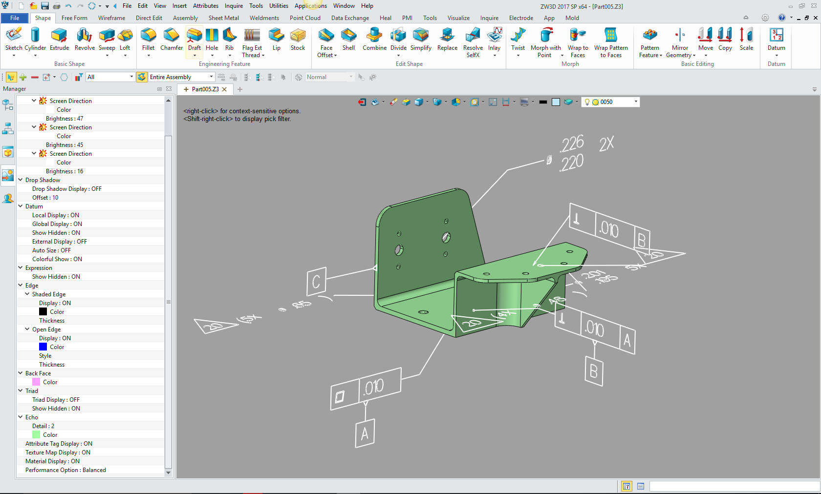
defined parts and assemblies. Now we had the PMI. PMI
PMI Annotation and Notes. Yes, that is in 3D Space! It is impossible to check or review.
AID
This is by far the worse engineering document ever
devised. It is a top down solution. It was never something that was
developed by Drafting, the group that handled all of the documentation. I have many articles describing the huge limitations
and convoluted process to use these documents. Why MBE/MBD/PMI Will FAIL Part II
Can the 3D Model Be Used as the Design Authority? So, what were the ramifications of implementing MBE
and the PMI? Of course, for some reason Boeing management does not
believe in an evaluation period. They seem to go cold turkey into totally
unproven technology. First Problem The PMI replaced the AID (drawing). If they don’t
need drawings, they don’t need draftsman. This is how incredibly
short-sighted Boeing management was. They eliminated the complete Drafting
Group and let the draftsman, now called Engineering Techs, go by attrition. They also eliminated the Document Control Group that was manned by inexpensive admin people. Replaced by expensive PLM consultants managing an unworkable system. The did this without any transition plan to get the engineers up and running handling the documentation, release and revisions. Sadly, it is still this way. Where it was draftings job to totally manage the documentation, it now became part of the 3D CAD engineers job. The engineer was now responsible for the design, CAD development, documentation and document control with wonderful unworkable PLM software. The Death of the Draftsman or “Where has all the talent gone?” Educating the New 3D CAD Engineer
Engineering Technologist? Engineering Technician?
Engineering Yesterday & Today Second Problem Boeing and MBE demands that the supplier use the native
CAD
file. So, if they did not have a seat of Catia 5 CNC they were
required to have a $5000.00 validation software that would compare the native Catia 5
model with the model they would use for CNC. It was, of course, apple to
apples. This software would generate an 8.5 x 11 sheet that had to be filed
if Boeing would come by and check. Why is validation important? The drawing had all of the part information as with the fully detailed AID. So you had a definition of the part in stone. The model offers a bit of a problem when making sure it is duplicated. A few CAD companies created a compare programs that would validate the CAM or Neutral file was the same as the native CAD file. Compare and Validation Programs? Band-Aids for Self Inflicted Wounds! Catia 5 and many of the major CAD system file can be corrupt. This could be a huge problem if discovered by the manufacturer. The model should go through a checking process to assure that they are good models. Lost In Translation! A Guide to 3D CAD Translation Formats Talking to Catia!! and other Popular 3D CAD Packages Another situation is the Boeing sends manual drawings to the supplier for them to convert to 3D Models using Catia 5 and I am not sure if they are to supply the 3D Catia model with the finished parts. You would think they would have an in house group that would do this. This would give the newbie engineer some valuable engineering and Catia experience. Sending manual drawings from a company that has based its documentation on MBE/PMI is inexcusable. If you would like to see an actual situation take a look at "A Drawing to 3D Conversion Failure!" at the end of this article. All You Wanted to Know About Drawing to 3D Conversions Third Problem There was no standard for PMI! There was no way to
read it without buy a seat of Catia 5 or Inovia, this is the same problem
with the other native files with PMI from the other major CAD programs. There were 3rd party
programs. My CAD software ZW3D reads the PMI native files of Solidworks,
Catia 5, NX and Creo. There were no standards so no free way to view these
files. There may be a STEP file format, but again they are not delivering the native file.
There are programs that allow you to detail the part for quoting. As you can see below there are no overall dimensions whatsoever. Besides inspection and CNC it is virtually worthless without a compatible CAD system.
Forth Problem I really do not know how they will handle assemblies. Assemblies in the past have been nothing but schematics showing how it goes together. A 3D model is pretty much useless since the assemblers have the parts in front of them. Plus how do they define an inseparable assembly? Fifth Problem Revisions, being model based they can not just mark
up a drawing and send it to the supplier. They have to revise the model
directly. As you know Catia 5 is based on the PTC Pro/e paradigm of strict
history and constrained sketching that can be very complicated to change depending the
complexity of the model. This, of course, is very dangerous. You would
almost have to have a validation function to check the model to see it there
were no other problem. Since you have not got an AID (drawing) for a comparison
this would be be visual only. This a playground for Murphy.
Sixth Problem Since there is no real standard the engineers start
bypassing the process and go directly to manufacturing. Where in the past
the engineering archive was the only source of engineering documentation.
This creates parts and assemblies that are not documented. The reason we
have standard documentation is also for legal reasons. You have to be able
to prove the design was safe or not when confronted with a legal suit. This article is quite shocking! Engineering should be thoroughly reviewed and checked prior to release. Engineering Documentation Today!
So, there you go. I could probably find seven, eight,
nine and on but I am sure you get the idea. Conclusion! Boeing moved from in stone manual drawings, to safe
3D models/AIDs to a virtually unworkable documentation MBE/MBD/PMI system on an
unworkable associated overly complex CAD system. When PLM was implemented, the InfoTechs and PLM Gurus took over engineering
documentation. Engineering management was now working in this newly defined
processes. It is quite interesting, document control pre-computer was a standard process developed by those that created and
maintained the documentation. Yet, Boeing thought nothing of tossing the
most important aspect of engineering to a group that would not look at how
it was done in the past and decided they were smart enough to reinvent the wheel. The results are devastating, but not only at Boeing,
but across the aerospace industry. Many of my associates working in the
field for decades have stated they do not think it can be salvaged. Imagine trying to create a functional system with
virtually no knowledge of the the past workable system? We are a minimum of 20 years past the
point of no return. Those that were in the know are now into their 60s and
retired. It is going to get worse and crumble. I wonder if
this is how civilizations come to an end.
Dimensional Engineers, Produciblity Groups, Quality Groups, Many Manufacturing solutions were created trying to make the computer work for them. But they created a mass of confusing overlapping processes. Engineering and manufacturing were completely separate entities in the past. Now they seem to be an intermingled mass of confusion. Engineering created an archive of released engineering documentation that was available to many different departments, in manufacturing you had purchasing and planning, you had marketing, Tech Pubs, it was even accessible to upper management.
Solution 1 - Standardized Cloud Based Document Control I have a concept called Cloud Based Document Control. I define it in these two articles. You really have to get a better control on the documentation not only in the archiving but in the creation. It is the only place you cannot have any short cuts. Standard Cloud Based Engineering Document Control Standard Cloud Based Engineering Document Control Part II Here is a simple way to make sure the supplier is always working with the latest version. I really wonder why no one thought of this. The Embedded Title Block! A PLM Solution! We need to eliminate PLM at least in the area of engineering and documentation and put engineering back in charge of the the quality and correctness of the engineering archives. Solution 2 - Engineers need to be well trained in "Standard" engineering documentation We also have to have well trained engineers to create the standard documentation or a group responsible for the quality and correctness. We need them proficient in detailing and tolerancing no matter the format. Can Engineering Survive without the Drafting Group? Recommendations to the New CEO of Boeing Solution 3 - Eliminate the dependency on associativity in the CAD system Associativity is a bit of a fraud. While in the beginning of a design it shows a bit of added collaboration it becomes a nightmare with document management. We have to realize the 3D model is part of our documentation. Document management has to be outside the CAD system in a cloud based archive. The parts and AIDs are easy, but we need to have the assemblies in there own single file or folder. I use a single model environment which is much easier than the major programs that would have to be packed and unpacked. 3D CAD Single Model Design Environment
Solution 4 - Educate engineering managment on the past engineering processes! Our engineering managers are far removed from an effective engineering environment and process. There should be classes on the history of engineering processes and documentation of the past. We truly need to put engineering back in the hands of engineering management professionals. In conclusion I will restate these two definitions. Engineering documentation is the language of Engineering. Engineering's total purpose is to make available concise, complete and unambiguous documentation to manufacturing.
TECH-NET Engineering Services!
If you are interested in adding professional
hybrid modeling capabilities or looking for a new solution to
increase your productivity, take some time to download a fully
functional 30 day evaluation and play with these packages. Feel free
to give me a call if you have any questions or would like an on-line
presentation. 206-842-0360
|
 Years
ago Adobe Acrobat 3D read Catia 5 PMI and delivered a STEP file and PDF with
the PMI!
Years
ago Adobe Acrobat 3D read Catia 5 PMI and delivered a STEP file and PDF with
the PMI! 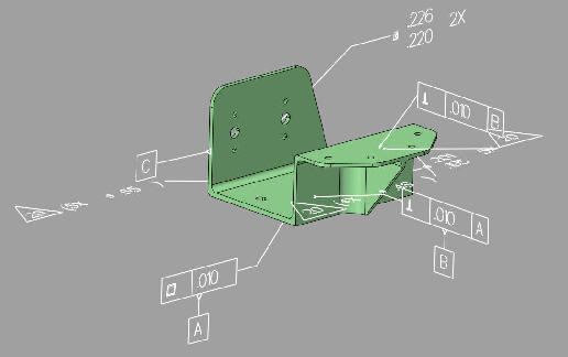
TECH-NET ASSOCIATES | RENDERING OF THE MONTH | CAD•CAM SERVICES
HARDWARE | TECH TIPS | EMPLOYMENT | CONTACT