CONCEPTUAL MCAD DESIGN
Which MCAD Paradigm is Best?
Solid Modeling is as close to creation as man has ever achieved. Today we can create anything we want, rotate it, view it, render it, animate it, etc. I will never forget the day when CADKEY (The first functional PC based 3D CAD system) released its first real time hidden line removal. No, it was not in full solid color like we have today, it was basically a wire frame on a black background. It was a miracle.
THE PARADIGMS
These are the paradigms presented in today's CAD world.
1. The Electronic Drafting Board
Notice I didn't say 2D. Unless you are creating flat patterns, you are usually using this to create drawings. Drawings are not 2D, they are documents describing real world parts, notice I didn't say 3D parts. Autocad was introduced in 1982 on a PC, providing the architectural world basic drafting. Many took this to the mechanical world. Luckily, my first CAD experience was detailing views generated from a 3D part. I did play with Autocad, it was an incredibly painful experience. It was truly not the tool for tomorrows mechanical design. I am shocked how many that are still using this clunker.
I was introduced to Computervision CADDS 4 in 1982. It was a 3D wireframe product running on a mini-mainframe computer running in a refrigerated room, $250,000 per station. This was the introduction of a new way to design. While on contract with Boeing in 1985, I found PC based 3D wireframe CADKEY on 2 Compaq computers . After two weeks of lunch hours, I convinced management that this was the tool we should use. We were using IGES to communicate with Catia 2, which was also 3D wireframe with some basic surfacing. CADKEY was the first fully functional PC based 3D CAD system. The selling point of 3D Wireframe was creating faster drawings. But they were not drawings, they were first fondly called the "Flatfile" by the Boeing Draftsman. I coined AIDs (Associated Information Documents) after the introduction of CNC on the PC using the model as a pattern. They were views associated to the 3D model. If the part changed it would be reflected in the AID. The wireframe was first used as 2.5 axis CNC in the late 1980's.
This was introduced in the mid 1980's. It was a boon to the industry. You could create net surfaced parts that could be used for 3 axis CNC and stereolithography (3D printing). A company asked me to add draft to a plastic part and add surfaces for 3D printing. Using Fastsurf in CADKEY, I quoted 55 hours, they were shocked "it didn't take us that long to design". I just said "Well, you should have designed it with draft." Later I did a similar job in FastSolids in CADKEY and it took me 15 hours. Robert White created Fastsurf and FastSolids as add on products for CADKEY.
Today, about 10% of us use surfacing. Solid modeling can not get down to some of the more swoopy designs or transitions. Surfacing is not a good paradigm for
mechanical design because of it lack of associativety and ease of editing. Most of the popular packages provide intermediate surfacing capabilities, that usually get us to about 95%. But there are advanced surfacing products like Alias and some surfacing provided by the high end packages to fill that last 5%. Here is an article where we had to have help to finish a project.
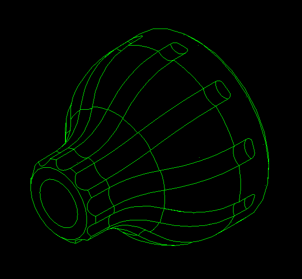
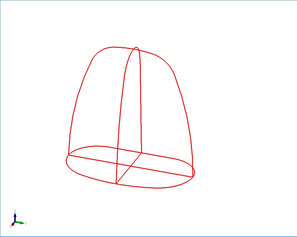
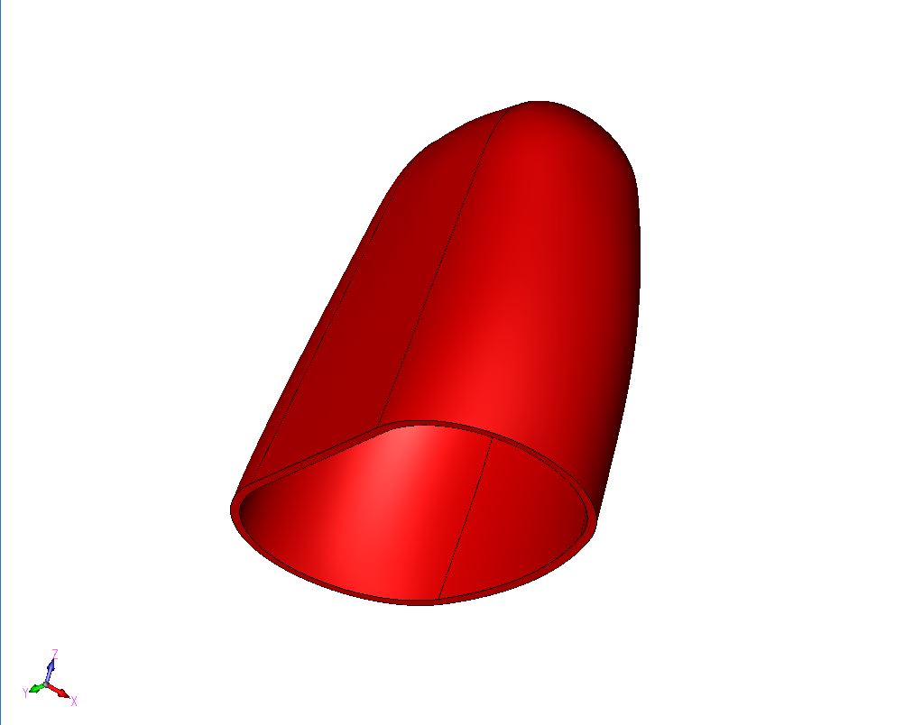
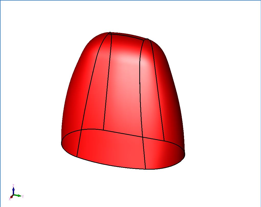
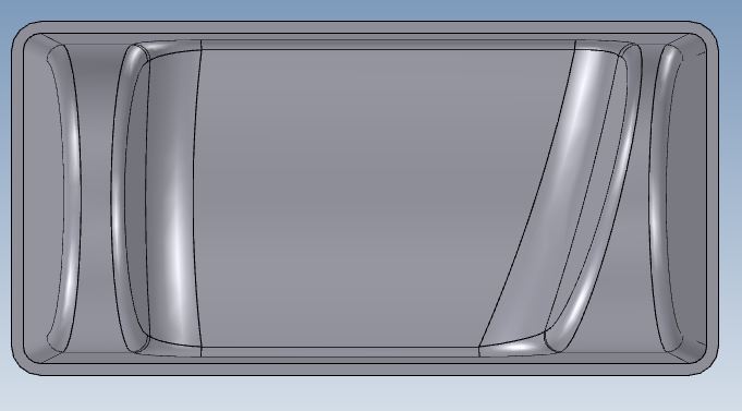
The image on the right is a Surface thickened into a Solid Model.
Parametric History/Feature Based Solid Modeling Paradigm
The first effective solid modeler was introduced with Pro/Engineer in 1988. It is a somewhat complicated design system. It has a very precise history base parent/child feature construction system. The parts have to be created in a certain way. Enter “Design Intent”. You have to really understand your design before you start creating the part. You have to understand how it is to be made and dimensioned. It should have really been called Pro/Designer. If the part is designed correctly you can have an automatic drawing. This is probably where the focus on the engineer being a CAD designer started. Now don’t get me wrong Pro/E is a very good program with many add on analysis functions, which does make it a good tool for engineers.
This system is very complex and hard to learn, causing the user to have to be a regular user. When you design a part the features are based on the earlier features. The skill and expertise of the user is paramount when using this system. When designing a part an experienced users has few problems. The problems show up when you have to change the part. The original designer even has problems with his own design if he is away from it for as little as a month. But the designer that has to take over the job may not be able to make the changes and may have to recreate the part. If this is a released part this can be very dangerous.
The Pro/e paradigm became the de facto standard. Soon Solidworks showed up, started with the help of some ex-PTC developers. It was soon purchased by Dassault Systemes which soon implemented this paradigm in its Catia 5. UG was releasing Solid Edge in 1996. Autodesk Inventor soon followed suit in 1998.
All of the above products use the Pro/E paradigm and all have the same problems. A very structured design process. It was soon found that this paradigm was very limited in interoperability. They could not use any of the data from the other systems. With Solidworks there were attempts to automatically create the history from non-native files but it was marginally successful. Even now you can recognize features but it leaves a lot to be desired.
Sadly, this paradigm is based on a limited constrained sketching design system. The training locks the user into a quite bizarre process of dimensioning and constraining the design entities. In this article I introduce what I call Streamline Sketching and Feature Based Modeling that increase productivity by 10X. Most of this design process is not based on the CAD system, just in how we do our sketching and inputting features.
I was selling CADKEY in 1987. CADKEY was a wireframe modeling package. There was a surfacing package called Fastsurf. Both programs offered a very good modeling package. Solid modeling was introduced in as FastSolids, this was a direct editing solid modeling system utilizing Boolean operations. I started my solid modeling at that time. The only other solid modeler at the time was Pro/E and it was my only competition. But it of course was in a different class offering much more engineering analysis at 10 time the cost with equipment, since it was based on a UNIX workstation.
CoCreate was also around at this time. It was a direct editing program. Now is being offered as a standalone product Creo Direct. It can be worked with PTC Wildfire offering the advantage of direct editing. PTC knew that they need this functionality to be able to work with non-native parts from other products, such as Catia and Siemens NX.
What do the popular CAD packages say about Direct Editing on their websites to promote this concept.
PTC
Creo
Direct
Easy to Learn
Easy to repurpose design
Lightweight - Smaller file size
Flexible
Rapidly evolve and explore designs
Maintain flexible design teams
Work with multi-source CAD data
Rapidly iterate designs
Siemens/NX/Solid
Edge ST
(Synchronous
Technology)
Reduced Design Experience
100X faster than closest two competing CAD systems
ECOs in seconds vs. hours
Biggest CAD breakthrough ever
No remodeling -- Edit foreign CAD data faster than in native package
Autodesk
Fusion
"3D
Modeling
for
Rapid
Design
Changes"
"Autodesk
Fusion
is 3D
modeling
software
that
showcases
intuitive
direct
manipulation
capabilities
for
unrivaled
ease of
use. By
uniting
direct
modeling
and
parametric
workflows,
Inventor
Fusion
offers
the best
of both
worlds.
Designers
can
freely
explore
complex
shapes
and
forms
while
maintaining
the
underlying
parametric
history.
Inventor
Fusion
makes it
easy to
open and
edit 3D
models
from
almost
any
source
and
incorporate
them
into
your
design,
enabling
rapid
design
changes
without
limitations."
SolidWorks Conceptual Design "Make Conceptual Design Your Business Advantage"
"Innovate in an instinctive, powerful modeling environment that gives you the freedom to design the way you want."
"Innovative conceptual design is the core of any successful product. SolidWorks Mechanical Conceptual, powered by Dassault Systemes 3DEXPERIENCE Platform, gives you an instinctive, powerful modeling environment focused on the four key elements of conceptual design:
Conceptual
Instinctive
Social
Connected
Dassault bothers me a bit with the name of their new product. What were Solidworks users doing before this product? Non-Conceptual Design!! Solidworks has been here since 1995. I don't even think this package has detailing functionality. So you still have to keep your Solidworks. At $2988.00 subscription per year, there are many better solutions that offer more flexibility and equal productivity. Also it is written in a different modeling kernel, we know that Dassault wants to get away from paying Siemens a royalty.
Update 10-22-18
Dassault again has renamed this program and released it in two flavors: Solidworks Product Designer and Solidworks Industrial Designer. Both are based on the Catia solid modeling system and are no more compatible with Solidworks proper than any other solid modeler.
So today PTC Creo (Pro/E with CoCreate), Siemens NX/Solid Edge with ST (Synchronous Technology), Autodesk Inventor with Fusion and soon to be released Solidworks Mechanical conceptual now all offer Direct editing. They see the writing on the wall. Today we need both paradigms. This leaves Catia 5 the only package without direct edit capabilities. Catia 6 is supposed to have it also, but those large companies that use Catia, like Boeing are probably a bit gun shy to move from Catia 5 due to the fiasco of the last move from Catia 4 and the incompatibility with the two versions, which they are still suffering. I am sure Boeing would not have purchased Catia 5, but now are stuck with it. I have heard Catia 6, even though released over 9 years ago, offers a very convoluted PLM system that is not ready for prime time even today.
Sadly these Direct edit add-ons have not provided the necessary functionality to allow them to take advantage of this productive tool. I have come to the conclusion that the dated Pro/e paradigm cannot effectively integrate direct edit functionality to use in the design process.
Innovative Part Design allows users to build a non-restrictive history of features that make up the design aspects of the part. Although it has a history of features, the system allows the user the ability to dynamically change the history order without inverse effects of feature dependency rules and restrictions. SmartUpdate technology within Innovative Part Design aids the users by intelligently managing the feature history giving predictable results when changes are made by the user. Innovative Part Design also provides a level of flexibility by allowing the user to refer to geometry elements regardless of the history order in which the geometry appears. This flexibility allows the user to work as if they were working with a physical object in their hands eliminating rules implied by the system.
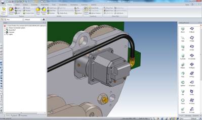
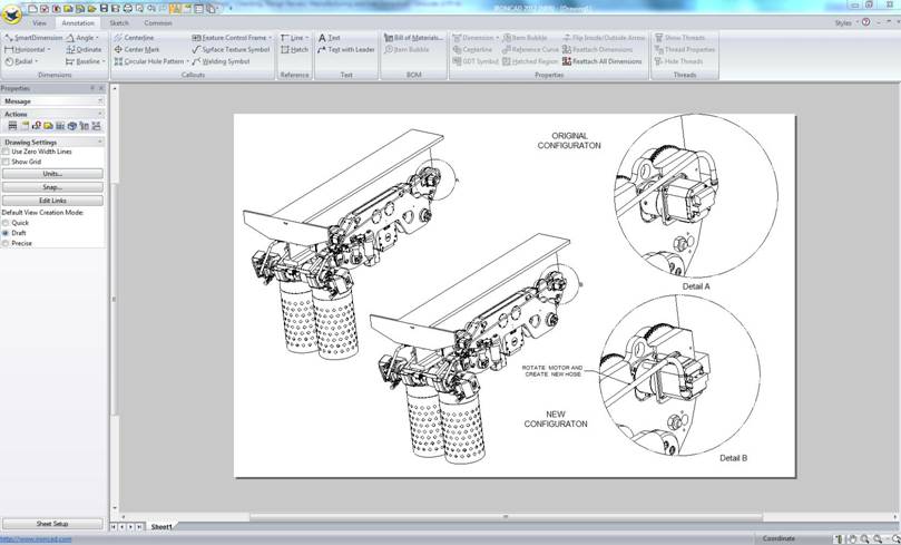
We are going to rotate the motor and revise the tube.
Here is an easy drawing of the change. No constraints, no modification of any released parts. The complete assembly in one file where all of the attendees can have and do a variety of concepts.
Since the Innovative Part Design supports features, users are able to add specific design rules to create parametric design intent. The advantage in this approach is to apply intent when needed allowing the user to place only the critical design intent during their design process without the need of system applied rules that may not apply to their design task.
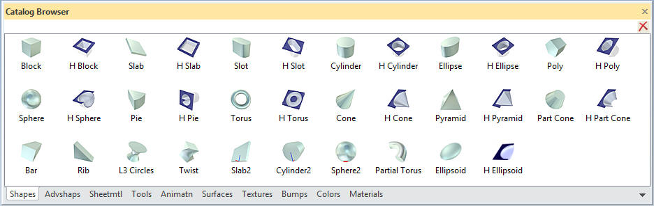
Drag and Drop Design from Standard or Custom Catalogs
This is where you pull feature shape (positive and negative, custom shapes, parts and assemblies) from a catalog to do your design.
This paradigm has three separate modules. A part, assembly and a drawing. This means you have to start naming parts as you begin your design. All parts are external. You can design in the assembly mode which doesn’t seem to be a problem. But PDM becomes a problem even if you are working alone.
Single Model Environment
This paradigm allows multiple parts in one file or space. Instead of creating external parts, parts and assemblies can coexist. This much easier in conceptual design, you can create many different iterations. All of the parts are available. They can be set up as external parts as the project demands. No PDM until the job is done.
Similar to the Single model environment, with most of the benefits. The different is that it is like the Pro/E paradigm except all parts and assemblies are in the same file.
Which is the Best for Conceptual Design?
Now that we have defined a few paradigms, which I am sure, many of you where not even aware existed.
Let's take a look at some examples:
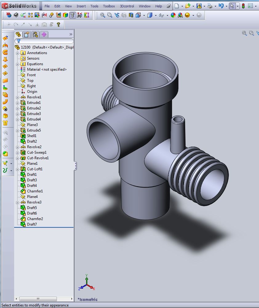
History based
This is a picture I am sure is familiar to many of you.
This is a relatively simple part. Now, you are not the original designer and you have to make the changes as shown in the next example. What do you have to do? You have to study how the part was made. The original designer could easily make the changes, probably not as quick as the next example, but much faster than the new designer. But from my experience, the longer you are away from the part the more difficult it is to remember how the part was made.
Remember
- There are basically no complex parts with direct edit?
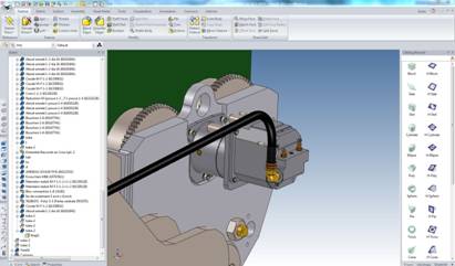
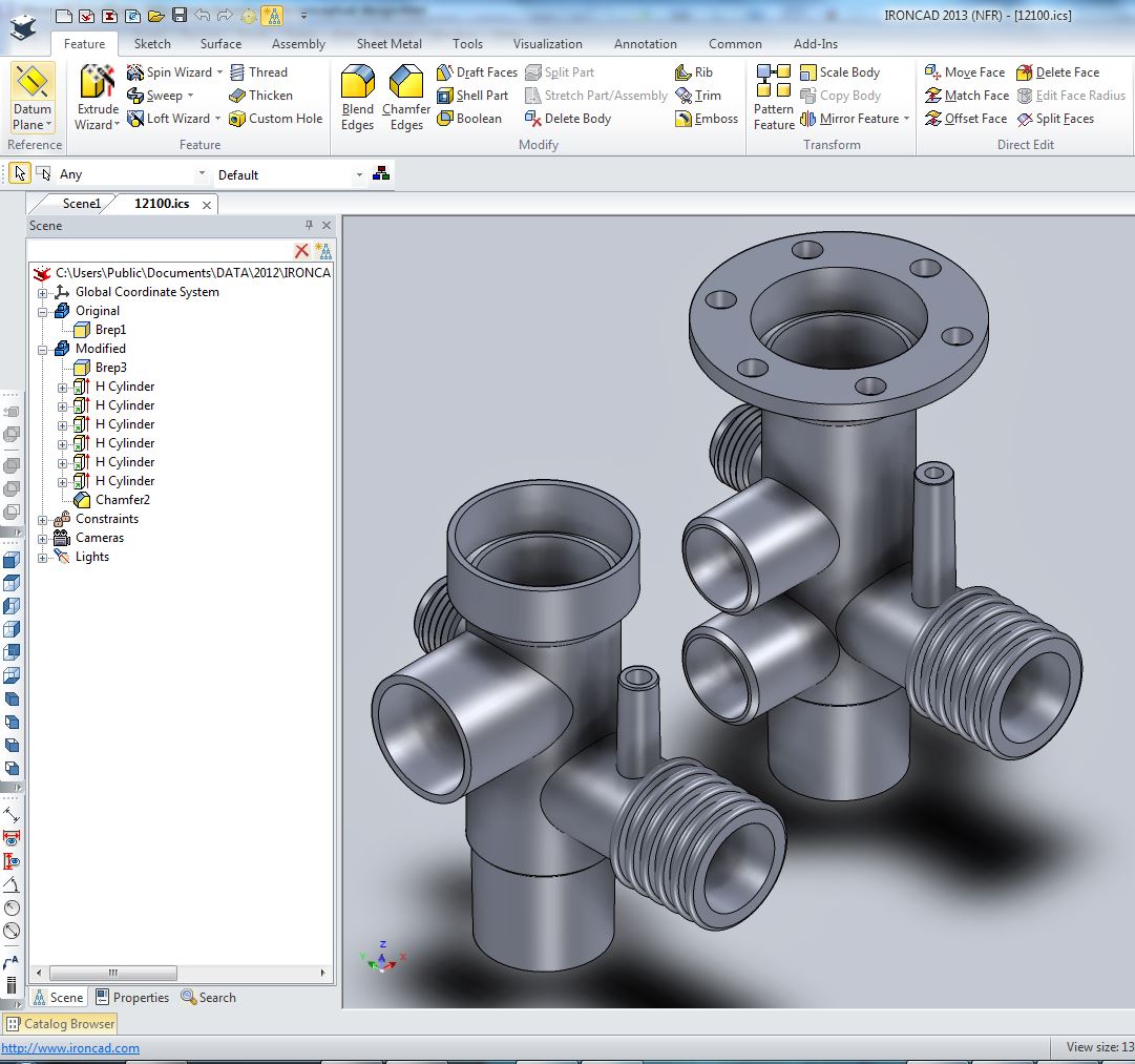
Now look at the above example. I have done some arbitrary changes to the part. Adding and modifying features. I could have easily eliminated some also. On the left is the feature tree, notice that the basic shape is one Brep. I have done many modifications that do not show up as features. This is the results of direct editing faces. Notice in the menu, on the upper right, you can see the Direct Edit functions that are available inside the program and are also available with the push of the right mouse button. Since IronCAD history is integrated, I have shown some features, like the linked holes and the chamfers. This all was done in about 5 minutes. How long would it take in SW?? Don't get me wrong, I am not one of those people that says any system is faster to design, since design is not a race. Design is a thoughtful procedure that is based on knowledge and experience. But I am showing you a more flexible design process of having both history and direct editing paradigms being directly accessible in one program. This is not having the best of both worlds, this is truly having a new world!!
Please notice that both of these parts coexist in one file. They is no separate part and assembly mode unless required by commonly used parts. This is called in the industry to day the Single Model Environment.
Design Intent is "absolutely" required with a Pro/E history only based system. You really have to plan your design before you start. In my view point this limits your freedom. This is a huge advantage of direct edit packages. I don't like to design in direct edit only package because I like the freedom of having my features easily available to me to edit in the conceptual design stage. I want to have the ability to design in history, but have the option to directly edit a face if required, instead of going back up the feature tree to a point where I can make the change without any repercussions.
This is an example of utilizing a direct face edit in the midst of the design process.
Here is a shelled shape. We select the face and with a right mouse click with select move. The Tri-ball comes up to manipulate the surface. We are going to rotate the selected face.
We rotated the Face 15 degrees.
We had a shell function in the history this shows that the shell did get upgraded.
Imagine working without worrying about the design intent. You have the freedom of incredible conceptual history design with the ability directly edit the part when the design requires it.
History or Direct Edit? The winner: History
In my opinion, History is the best for conceptual design. No matter which history program you use, having access to the feature for change is by far the fastest and easiest way to go. You can get the job done with direct edit, but it just is not conducive with new design.
But to change the design, history has some problems depending on the complexity of the part. Direct editing has some huge advantages. When you directly edit a part you don't have to worry how the part was made. If you watch a webinar of direct editing only packages they usually show how to edit dumb models, never in conceptual design.
But why settle for one paradigm when you can have both. IronCAD has both integrated into the system!
This is not having the best of both worlds, this is truly having a new world!!
The Design Environment! The winner: The Single Model Environment
Now lets take a look at the design environment. The separate part and assembly, which may be the answer in the 1980's, is a bit of a clunker today. You have to start naming parts and putting them in your assembly. Yes, I know you can design in context and create the external parts in the assembly.
But to design in a Single Model Environment allows much more productivity by putting the data management on end of the project instead of up front. Many times the parts are unique to that project and can be left in the assembly to be detailed from there if required. Some times the parts or assemblies may not be used in production, you can actually archived them in the same file and keep them for future reference. This is a much better environment for the individual designer and smaller projects. I believe this is the most important process to increase productive. Sad to say there is only one history base system that utilizes the Single Model Environment, which gives it a huge edge in productivity.
What's been left out?
Innovative Product Design and with Drag and Drop Functionality!
Why? Because they are only included in one package, IronCAD. Incredible freedom in design with Innovative Product design. It is the only package with standard catalogs or custom catalogs that can have common parts for different projects from which you can drag and drop in to the design scene.
IronCAD is also the only package with both History and Direct editing integrate into one package. Why would you suffer with clunky external direct edit modules when you can have ability to direct edit with a push of the right mouse button. We know that most design does not require direct editing functionality, but would it be nice to have it part of your design capabilities.
IronCAD the only history base system that is a Single Model Environment. Just start doing your design. All parts and assemblies are available to you. Create as many iterations of your design as you want without worrying about external parts. You can copy and paste parts and assemblies in the same file or a different file. Just imagine how easy that would be. You don't care where the part was made you just start working on the part. No need to access a separate module.
We are describing a high level of freedom and flexibility in your design. So it is not a paradigm which is best that is important, it is a program that offers all of the paradigms for conceptual design in one fun, yes fun, easy to use package.
Hybrid modeling allows wireframe, class A surfaces and solids to coexist in
one useable space. This is where the major CAD programs are heading.
But with their dated Pro/e paradigm structured design process they
cannot
integrate it into their existing products. Dassault may be the first
to confront this inadequacy in Solidworks with the introduction of
Solidworks Product Design program. This looks like an attempt to incorporate
robust direct edit functionality, it has no surfacing functionality,
which is mandatory for a hybrid modeling package. But I am not sure who will use
this package, both of my solutions easily outperform it and at an
annual cost of $2988 it does not seem to be cost effective.
Even though ZW3D is much like Solidworks (more like NX) in operation, it is much easier to use since it can easily do complete projects in one file including drawings. IronCAD/INOVATE offer a much easier paradigm for conceptual design, but when you have to step out of the solid modeling box ZW3D offers that extra flexibility. You truly want to end up with a solid model. Especially if you have to deliver the design to a company for further development.
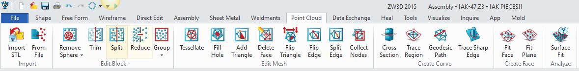
ZW3D always had advanced capabilities handling "point cloud" data. Mostly in turning them into surfaces. It also could work with .stl files on a rudimentary level. But that all changed with version 2015. They added a robust menu of functions that can manipulate .stl files not matched by programs at 10x the price.
Take a look at the menu:
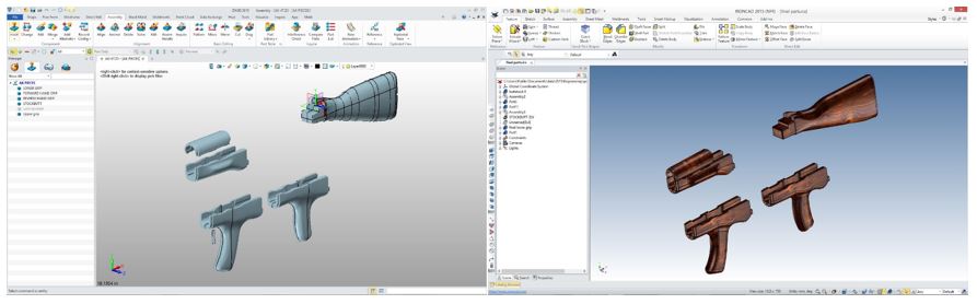
To do reverse engineering you need full hybrid modeling functionality. You need wireframe, advances surfacing and, of course, solid modeling. Take a look at the project below and the ease of converting "scanned" data in to manufacturable parts.
If you are interested in adding professional
hybrid modeling capabilities or looking for a new solution to
increase your productivity, take some time to download a fully
functional 30 day evaluation and play with these packages. Feel free
to give me a call if you have any questions or would like an on-line
presentation.