|
Industrial Design: “The role of an industrial designer is to
create and execute design solutions for problems of form, usability,
physical ergonomics, marketing, brand development, and sales.” I have been in the industrial/mechanical engineering business for over 50 years. I wasn't even aware of Industrial Design until I jumped disciplines into Plastic Product Design from Aerospace thanks to my Computervision CADDS 4 3D CAD experience in 1982. The 1980's - 3D CAD - The Beginning I met my first ID when I sold him a seat of CADKEY. It was the first functional PC based 3D CAD system. He was a great designer, we would go into clients together and he would sketch a concept or two right on the spot. Then hand it to me to develop. Not that he couldn’t do it himself he is a skilled CADKEY and IronCAD user and engineer. He was one of the first that jumped into CADKEY with Fastsolids and Trispectives to utilize the solid modeling functionality of both programs. After selling CADKEY for years I was
introduced to Trispectives in the middle 1990's, a graphic design program. FastSolids was
just released for CADKEY and with Trispectives, both being based on
the ACIS solid modeling kernel, we could pass solids back and forth
with ease.
This was incredible. With CADKEY we would create precise mechanical
designs and with Trispectives we could create realistic renderings
and animations. We could put images on faces, add transparency it was incredible.
This was in the middle 1990’s when others were struggling with the
complexity of Pro/e.
Trispectives was purchased by a company
that was an OEM for CoCreate (today's Creo Direct) and they produced
IronCAD. IronCAD has the only integrated history and direct editing
plus surfacing in
the program. All are used in the design process (I will show the
benefits of this later). This product was released in 1998 and
introduced with the
“Innovative Part Design”. This paradigm offers levels
of "Conceptual Design"
miles above the current Pro/e clones (Solidworks) no matter how much you paid. To
match IronCAD for Industrial Design you would have to have extra
modules for many of the CAD system and even 3rd
party programs, costing a fortune with very little ROI in
productivity.
Industrial Designers are not Mechanical
Engineers, their design needs are much different. The Pro/e Clones
are designed for Mechanical Engineering and focused on the problems of
mechanical engineering with complex history based design and
separate part, assembly and drawing files with complex integrated
PDM or PLM. While this may be good
for designing machines (I don't agree) it is a horror show for fast, easy
conceptual design especially as it relates to design changes.
We offer two incredible highly productive, highly creative and cost effective solutions!
Welcome to Complete Design Freedom
Innovative Part Design
1. The
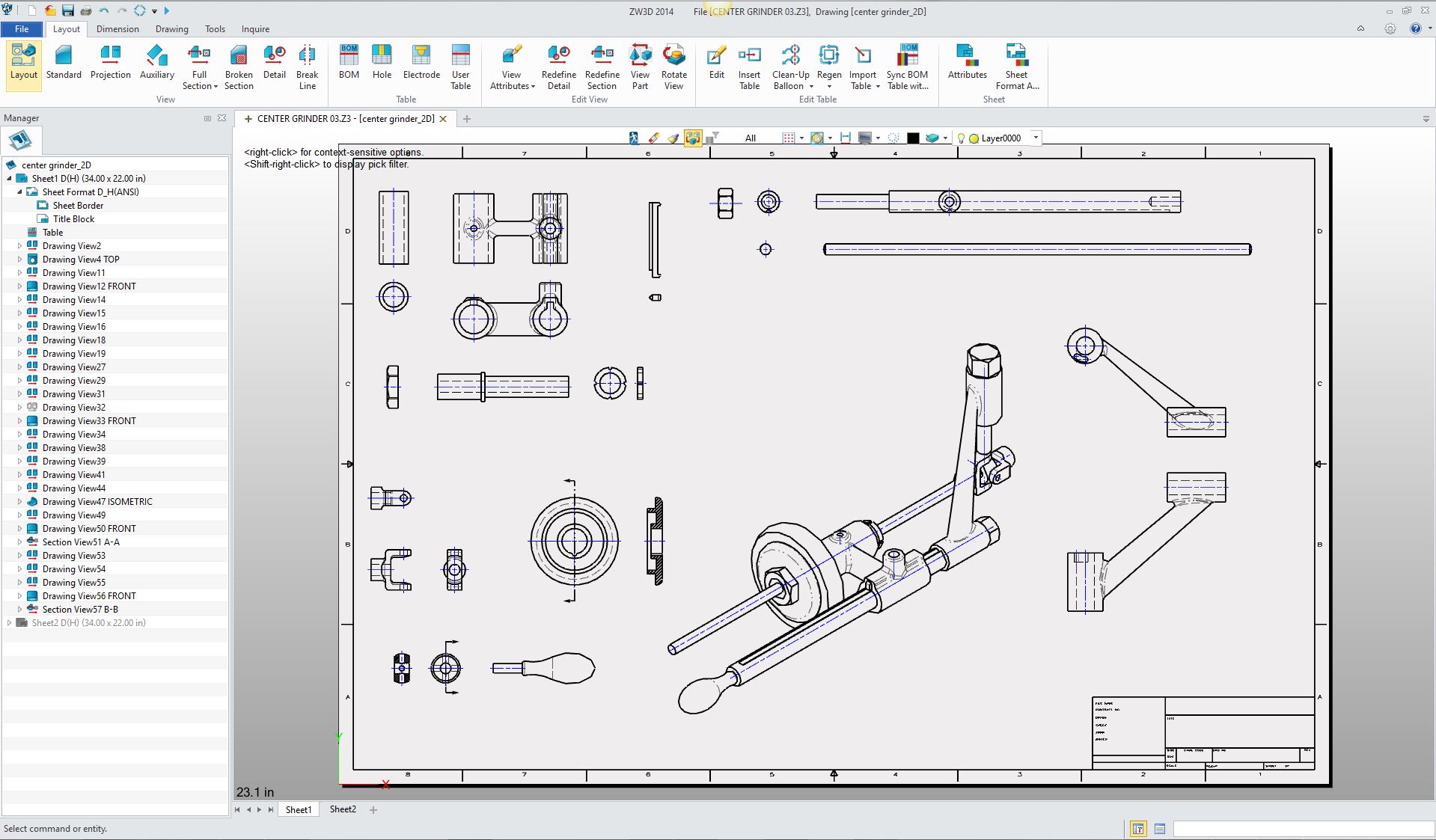
Single Model Environment In the Single Model Environment you can do your complete project or multiple projects without defining external parts. The Pro/e paradigm was built for drafters. Most have experienced this, you create your parts with a complex unforgiving History/Feature design with constrained sketches and you shudder when you think of changes. You have to insert the parts and constrain them in the assembly module. The only constant in design is change. As designers we may need a couple of different iterations to show the client. All of the popular CAD systems have finally admitted that the sketch, sketch, constrain, constrain paradigm is dated and hard to modify and have introduced direct editing. Is 3D CAD Productivity an Oxymoron? The sketch and constrain design technique is very time consuming. In this article I introduce Streamline Sketching and Feature Based Modeling. It increases design productivity 10X. 3D Modeling Techniques Defined Here is are two videos comparing the design process of IronCAD compared to SW and Pro/e paradigm. I don't particularly care for speed comparisons of CAD systems. We don't design for speed. Design can be a time consuming process, even with CAD, involving many considerations. But this video shows the Single Model Environment and drag and drop design in action. Notice that no external separate parts are made. You can establish external reference parts at any time in the design process.
In the Pro/e clones the parts are created
separately. They do offer in-context or top down design but
again like most Pro/e functionality is overly complex,
taking
your mind off of the goal “Functional Creative Design”.
In the Single Model Environment you have parts freely coexisting in a
single space. Easily creating mating parts into easy to maintain
assemblies. All in one file. Yes, you can have external reference
parts.
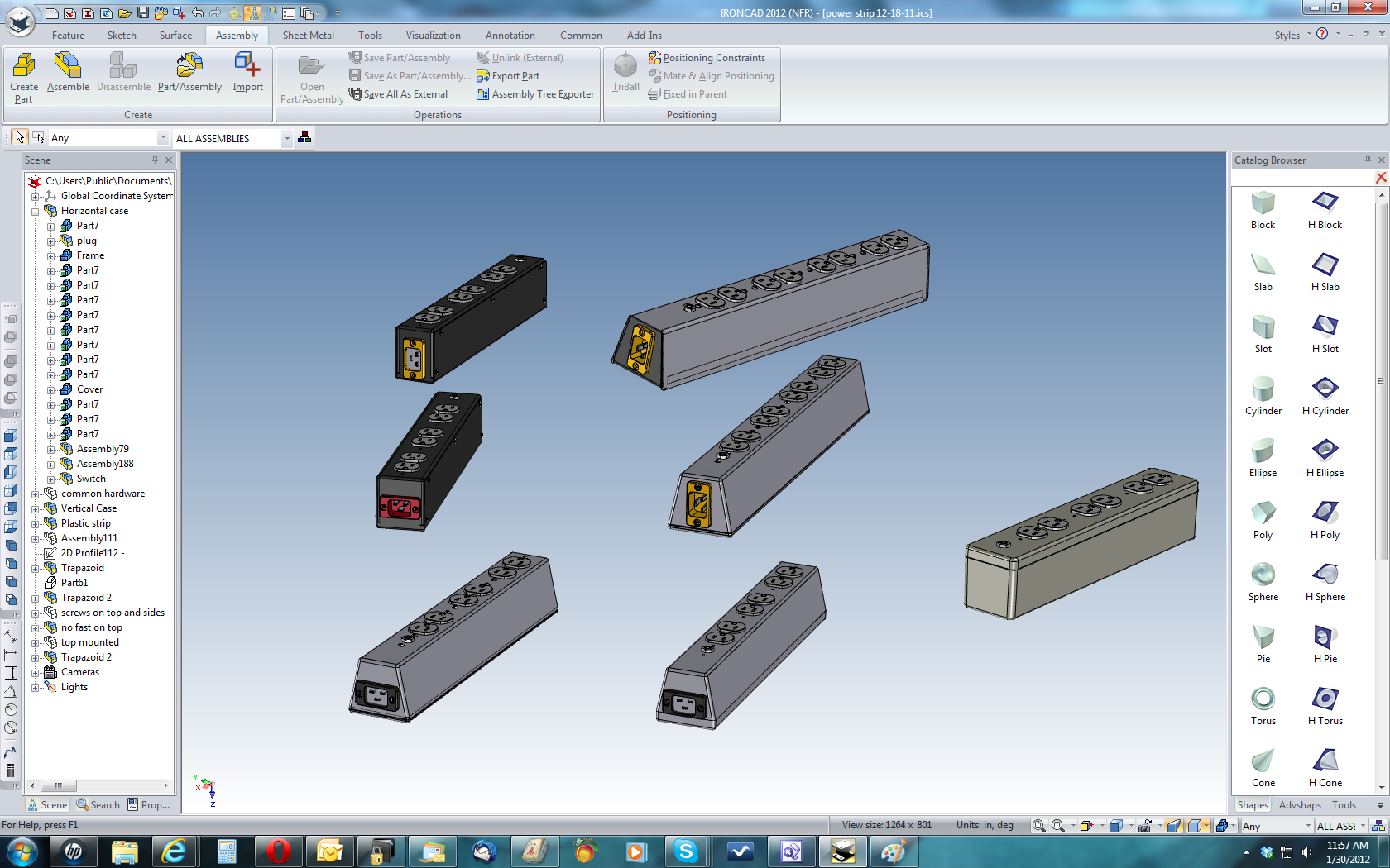
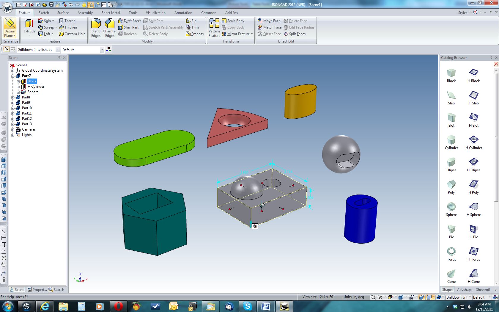
Above you can see the different designs for plastic and sheet metal power strips. As we work with the customer the design develops. As you can see they are all in one file. Not only can we work with similar parts we can work with totally dissimilar part or assemblies. On the right is a catalog of shapes, advanced shapes, colors, textures, tools (such as custom holes, fasteners, gears, bearings, etc,), sheet metal or custom catalogs with features, parts or assemblies. This view is in an exploded configuration, not affecting the original location of the parts. 2. Drag & Drop Design from Standard and Custom Catalogs
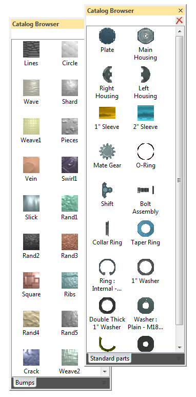
The catalogs offer more than just features, shapes, parts and assemblies. Tools: Includes specialty shapes like bearings, hot and cold formed steel shapes, custom holes, Helix, fasteners, gears, etc. Sheetmetal: All of the sheet metal features can be drag and drop into the scene. Of course these sheet metal features can coexist with the all of the other parts and assemblies already created. Animation: You can drag and drop animation controls on your parts and assemblies to create fast and easy animations. Appearance: Drag and drop color, texture, bump, and realistic characteristics such as glass, metal, wood, plastic, etc. This increases your productivity incredibly. You truly have to experience drag and drop design if you are stuck in the sketch, sketch, constrain, constrain world of the Pro/e paradigm with clones such as NX, Solid Edge, Solidworks, Inventor and Catia 5. But there is one more fact, you can still design in that world when there is a need. The features and shapes are driven by an embedded sketch.
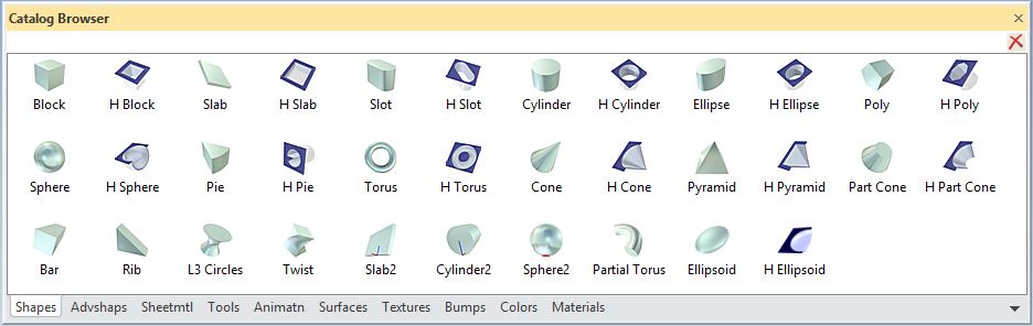
Above: This is a very easy to use interface, but it has very sophisticated and powerful capabilities. Let’s take a look at some of the basics. Look on the right side and notice the shapes in one of the standard catalogs. I have Drag & Dropped some shapes into the work space. You can see some what are called hole or negative shapes Drag & Dropped on the solids. On the middle block you can see the Push/Pull handles. On the left is the scene browser or tree. You can see the block highlighted and showing the features that make up the part. Also notice that all are separate parts in the same space without external references. You can make them external reference parts or insert referenced parts if necessary.
3.
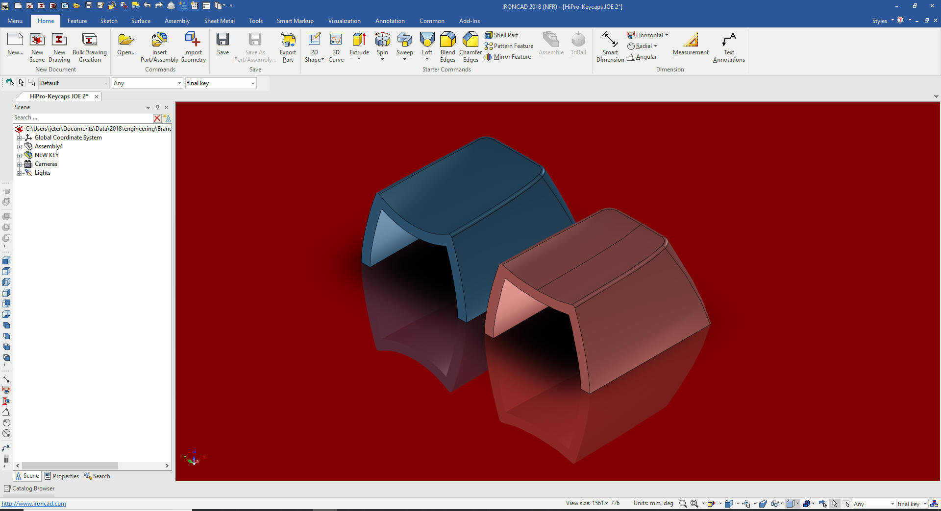
Integrated History/Direct Editing and Surfacing IronCAD has integrated history and direct edit functionality.
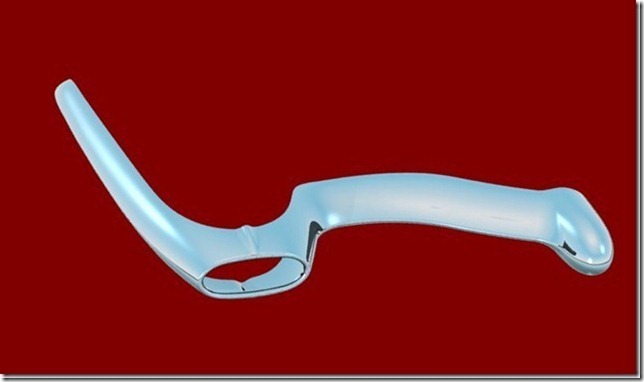
This phone was
originally designed by an ID firm in Pro/e and developed in
IronCAD and is the first project in
this article Left is a rendering.
Right is a picture
Many of you cannot imagine not having a history based system available for design, well neither can I. IronCAD having both integrated into one system gives you the most flexible design tool available. It truly is a pleasure not to have to worry about design intent. Here is an example of IronCAD and its direct editing capability: Here is a shelled shape. We select the face we are going to move and with the click of the right mouse button. The Tri-ball comes up to manipulate the face. We are going to rotate the selected face. We rotated the surface 15 degrees. We had a shell function in the history this shows that the shell also got updated. Imagine working without worrying about the design intent. You have the freedom of incredible conceptual history based design with the ability to directly edit the part when the design requires it. IronCAD works a bit different than ZW3D when doing direct editing. IronCAD consumes the affected features making direct editing a part of your design process. ZW3D makes every direct edit modification a step in the history. This is the way most of the history based programs handle direct editing. Which can be a bit problematic. IronCAD and ZW3D allow you to combine the history into one Brep. Can you imagine blowing all of your history away? "Oh, the sacrilege!!"
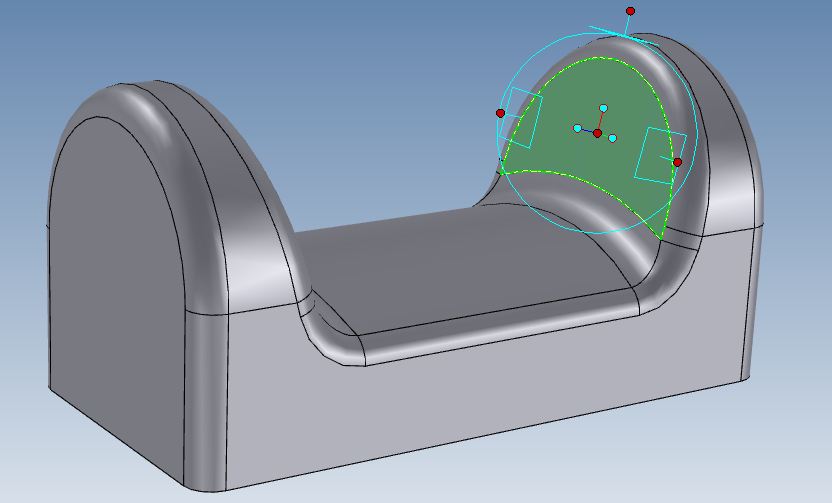
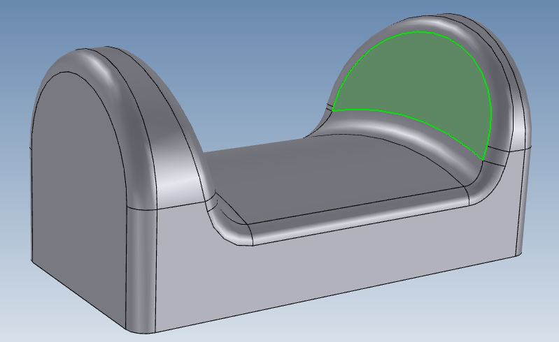
Surfacing
IronCAD offers
good surfacing to enhance the solid modeling.
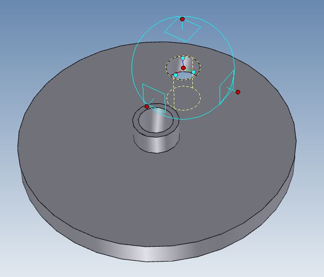
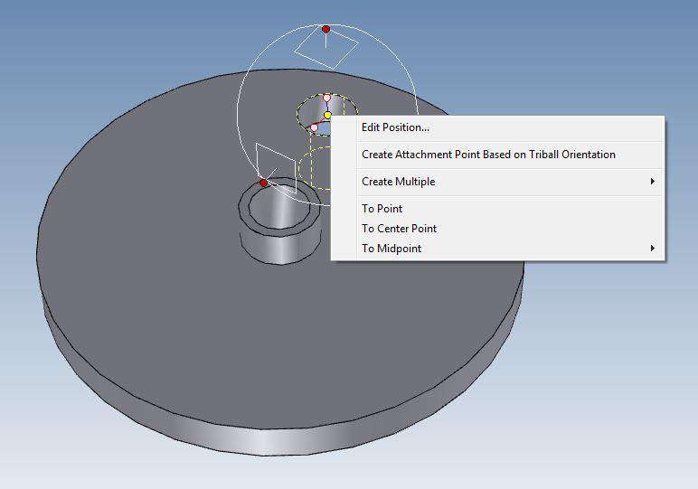
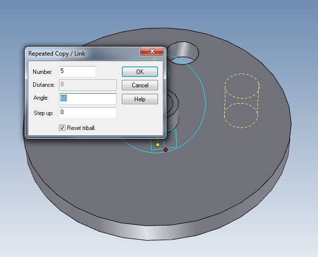
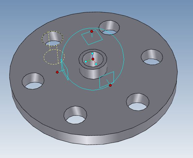
A Simple Case for Hybrid Modeling 4. The Incredible Tri-Ball - Often Copied but Never Duplicated (Virtually all direct editing packages have a Tri-Ball Clone, including SWPD) Many of you have seen feature, part and assembly manipulation tools show up in your programs or in presentations of other programs. I am sure you thought they were very clever and productive, but a bit cryptic. Ever wonder where they got the idea? The Tri-Ball has been with Ironcad since the Trispective days in the early 1990's. It is not just a feature, part and assembly manipulator. It does so much more. It locates, copies, mirrors, links, it is used to manipulate surfaces, mating parts, splines etc. You have seen the Tri-Ball used above in direct face editing. The Tri-ball with a push on the space key allows the Tri-ball to be moved to a location where you may want to create a pattern. Here is how it works: I have created a flange with a hole and now to create a bolt circle. We push the space key and that turns the Tri-ball white which means we can move it to the location where we want to rotate the hole. Now that we have the Tri-ball in the correct location we can now perform the operation. Notice you can select to reset the Tri-ball to the original position after the procedure. Below shows the holes installed. We could have also created an editable pattern. As you can see the Tri-ball power even in this simple example.
The above five functions are described more in depth in this article.
Five Functions that
Increase CAD Productivity!!
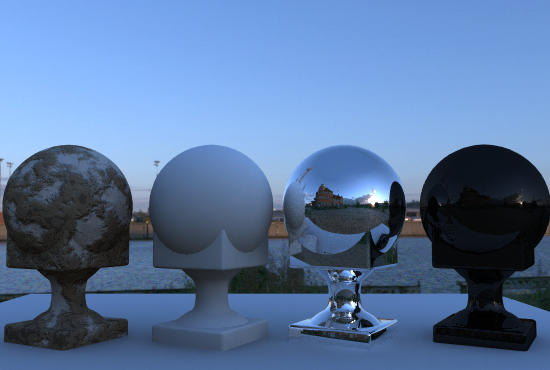
5. Rendering and Animation
One of the things that an ID needs is to be able to quickly present
their new project. Since both IronCAD and INOVATE started out as
graphic design programs they have realistic rendering and animation as an
integrated part of their program. If you have more realistic needs,
both or our packages have an integrated KeyShot option.
Most of the CAD programs are for Mechanical Engineering and realistic
rendering and animation depend on a separate option or a 3rd party program.
The Mechanical Engineer rarely gets into realistic rendering, a
screen shot usually serves the purpose to get the idea across. But
as an ID you have to get the idea across to convince someone it has
to become a reality.
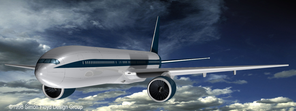
This was done Years ago by Simon
Floyd in IronCAD!
Realize this was done in one
file no external parts!
INOVATE - Modeling only package
IronCAD - Complete CAD system and adds two easy to use
documentation modules (one is an AutoCAD clone), Sheet Metal, intermediate Surfacing and Intellishape functionality. Even though IronCAD offer incredible ease of
use, high productive conceptual solid modeling design, it's surfacing is not
much more than a limited enhancement for solid modeling. You do not have
the robust surfacing capabilities of a more advanced surfacing
package, such as ZW3D. Surfacing is not included in INOVATE. Enter ZW3D - Free Form Class A Surfacing. No, it is not an advanced surfacing package
like Alias. But really, who needs $20,000 of surfacing software to
do product design. Yes, it is important when you are sculpting
something like an auto body but rarely do we need those kinds of
capabilities. It is more on the order of Rhino with functional solid
modeling, shape morphing and wrapping and includes reverse
engineering point cloud surface conversion and integrated
documentation. You do your complete project in one file. ZW3D Lite offers all of the
incredible solid modeling on the order of Solidworks. It has robust
primitive shapes that increase productivity 30% along with
sophisticated sketching. It also
includes direct edit functionality. It has one unique feature that
makes it stand out from the rest of the history based solid modeling
packages. It can have the parts, assemblies and drawings all in one
file. IronCAD has an external drawing module. This is a great
add-on for INOVATE to provide drawings or documentation.
ZW3D Standard is by far the
most cost effective CAD solution available. It adds Free Form Class
A surfacing, Shape Morphing/Wrapping, sheet metal and reverse engineering to the Lite
package. With the surfacing being integrated with solids and
wireframe design it moves to the level of a Hybrid Modeling
solution. Advanced Surfacing - Surfacing only Let's take a look at an advanced surfacing
program such as Alias. It is much more difficult to do product
design with a surfacing only package. It is composed of 2D/3D wireframe
and surfaces. You have most of the commands you use in solid
modeling. Extrude, Spin, Sweep and Loft. Solid modeling is a much
better process to do the basic product design. I have found the
advanced surfacing experts are really not designing but tweaking
designs to assure that the surface produced is aesthetically
pleasing. These are not your run of the mill designers, they are
sculpturing professionals. I would say that advanced surfacing is
required by only 5% of the industry. I was lucky enough to have two intro classes
on Alias presented by Autodesk Alias application engineers. They
taught us how to make a Snowman. Actually this was a mechanical
engineering bunch and we just shook our heads, knowing we could make
a
snowman much easier in a solid modeler. Alias does, however, have the
most bizarre user interface I have ever seen. I got to play with it and the learning
curve is very long. This is a professional package that takes years
to master. Take a look at the reverse engineering job
on a 1959 Corvette Bumper. I could not get the correct surfaces and
had to go to an Alias expert.
REVERSE ENGINEERING SUCCESS!
As you can see this was beyond the CAD system I was using.
How about Rhino?
I have taken a class in Rhino. It was a week class
and we spent most of the time making a Duck. I was selling
mechanical CAD and I just scratched my head. Sadly, not one moment
was dedicated to mechanical design. I guess that pushing and pulling
an odd shape in some form is what the common surfacing person does.
The product was a bit too Autocadish for me and even though I had a
copy I never utilized it having most of its surfacing capabilities
already available ZW3D.
Rhino's solid modeling really does not exist. Boolean only solid
modeling design has completely disappeared and is completely
unproductive.
Now let me introduce you to Hybrid Modeling
Hybrid modeling allows wireframe, surface and solids to coexist in
one useable space. This is where the major CAD programs are heading
next. But with their structured design process they may not
be able to integrate it into their existing products. Dassault may
be the first to confront this inadequacy in Solidworks with the introduction
of Product Designer. This looks like an attempt to incorporate
robust direct edit functionality. But I am not sure who would use
this package, both of my solutions easily outperform it and at an
annual cost of $2,988.00 it does not seem to be cost effective. I
have yet to see anyone using this product. They do not offer an
evaluation without talking to a salesman. Who wants to talk to a
salesman?
CONCEPTUAL DESIGN
-
Which CAD Paradigm is Best?
Hybrid Modeling in ZW3D with "Best in Class Overdrive Kernel"
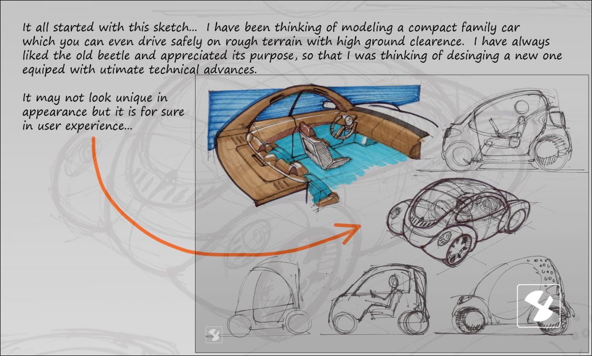
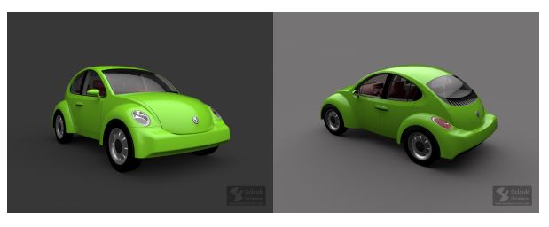
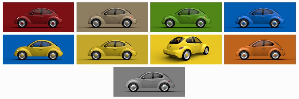
This is the most incredible presentation of Hybrid CAD modeling you will ever see. If there is a "Master" in the art of CAD, Selcuk Ozmumcu is it.
Watch this slide show as Selcuk designs a car before our eyes!! Truly, amazing. Using all of the graphic tools Hybrid CAD has to offer.
Spherical | Modeling Process Slide Show
Spherical | Colors Set
Selcuk Ozmumcu incredibly creative and is
the most proficient and prolific modelers I have ever met. He is a
professional Solidworks user and has now moved to ZW3D, fully
utilizing the Hybrid Modeling including Wire Frame, Surfacing and
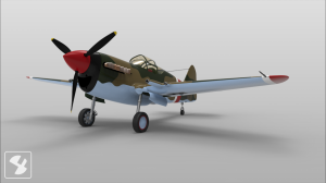
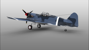
Solids. Here is what he said when I asked him why he
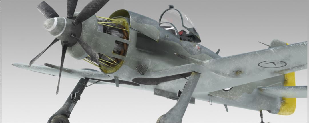
moved: Watch as Selcuk designs the P-40
Here is a couple of the final images of his P-40.
Please visit his website to see more of his
incredible aircraft and other 3D models. Now to continue with the article and show
you some of the reasons why Selcuk moved to from Solidworks to ZW3D
Standard. Besides being a
great Conventional History and Direct Edit design, ZW3D offers much
more design flexibility with its powerful surfacing, morphing and
wrapping. All of this power, not costing tens of
thousands, but at a cost all can afford!!
ZW3D is very similar to NX in performance and capability at
thousands less. It is very easy
use since it handles parts within assemblies much better and able to
do complete projects in one file. IronCAD/INOVATE offer a much easier paradigm for conceptual design,
but when you have to step out of the solid modeling box, ZW3D offers
that extra flexibility. You truly want to end up with a solid model.
Especially if you have to deliver the model to a client or
mechanical designer for further
development. It is important to show you real life
projects as it relates to CAD outside the realm of the Pro/e Clones. Take a look at
this
projects. You can see other projects at our
Engineering Services.
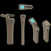
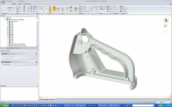
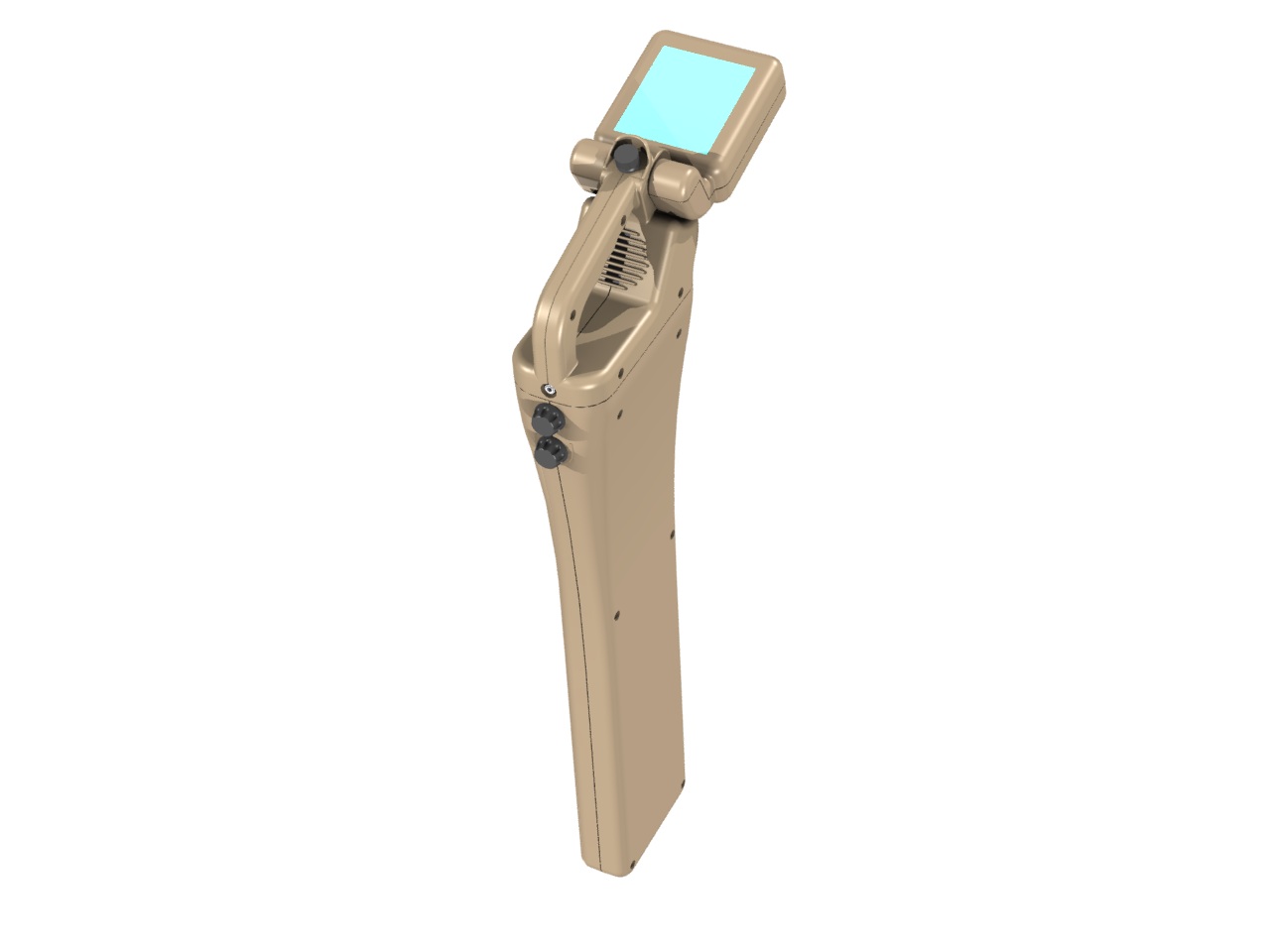
The Prototek
Linefinder
Prototek Redesign
Prototek Project
Reviewed Our CAD Solutions With our CAD
solutions you can start providing your own design services, competing with
and even outperforming the largest Industrial Design Firms at a
price you can afford. We can start you at any
level. If you have a large design firm you can lower you CAD costs
and increase your productivity. With our CAD
translators you can read the native
files from *Creo (Pro/e), *NX, Solid Edge, *Solidworks and Inventor.
Read/write Catia 4/*5 and all of the standard format. * Includes the ability
to read PMI
Universal CAD Compatibility is "NOT" Here!
TECH-NET Engineering Services!
If you are interested in adding professional
hybrid modeling capabilities or looking for a new solution to
increase your productivity, take some time to download a fully
functional 30 day evaluation and play with these packages. Feel free
to give me a call if you have any questions or would like an on-line
presentation. |
 3D
CAD
FOR THE INDUSTRIAL DESIGNER
3D
CAD
FOR THE INDUSTRIAL DESIGNER