|
So, what "HAS" gone wrong
|
|
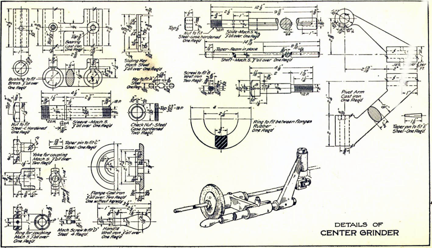
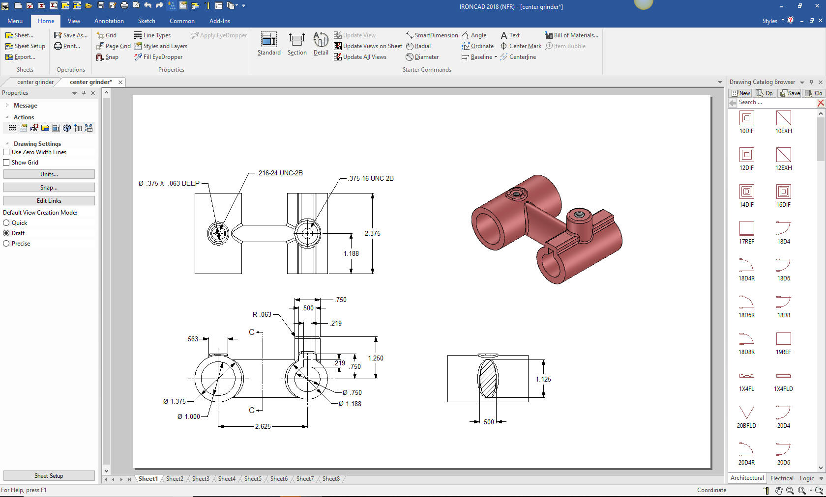
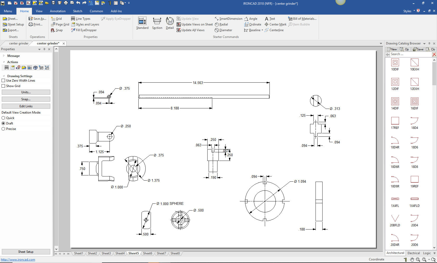
So What "HAS" Gone Wrong with Engineering? So What "HAS" Gone Wrong with Engineering? Part II The Tale of the Center Grinder! I have used the above drawing for many articles. But this
may be my most profound use of it.
Since we are dealing with 3D CAD only, we do not create drawings. We create AIDs (Associated Information Documents). They can look just like a drawing but they are very different. They are made up of views generated and associated to the 3D model in a documentation module in the 3D MCAD system. So when I refer to the AID, please realize this are documents that look like the "2D drawing". I hate that term, what other kind of drawings are there. AIDs are "not" drawings. A drawing is made up of non-associated orthographically projected views. The drawing or AID was the only document delivered to manufacturing to define the parts until around 1990! There are 4 types of AIDs that come out of a 3D MCAD system.
The above drawing is a detailed assembly. All of the
parts are defined and an illustration is used to show how it is assembled. This is all that is necessary to manufacture the
“Center Grinder” If anyone can tell me how the center grinder works would be very
cool. This detailed assembly has all the information that is
necessary to make
this product, defined on a single “D” size sheet? It has the material and the process and fully defined
on one sheet. How many of you could convert this to 3D models? It
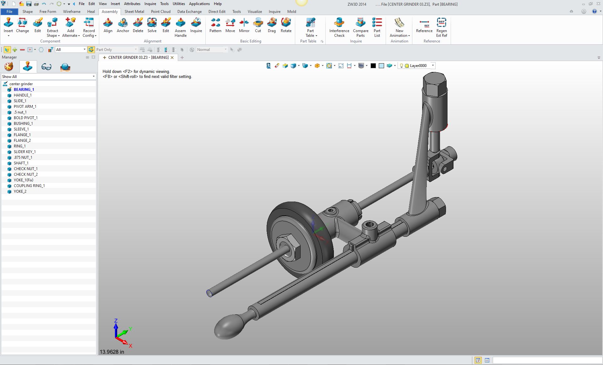
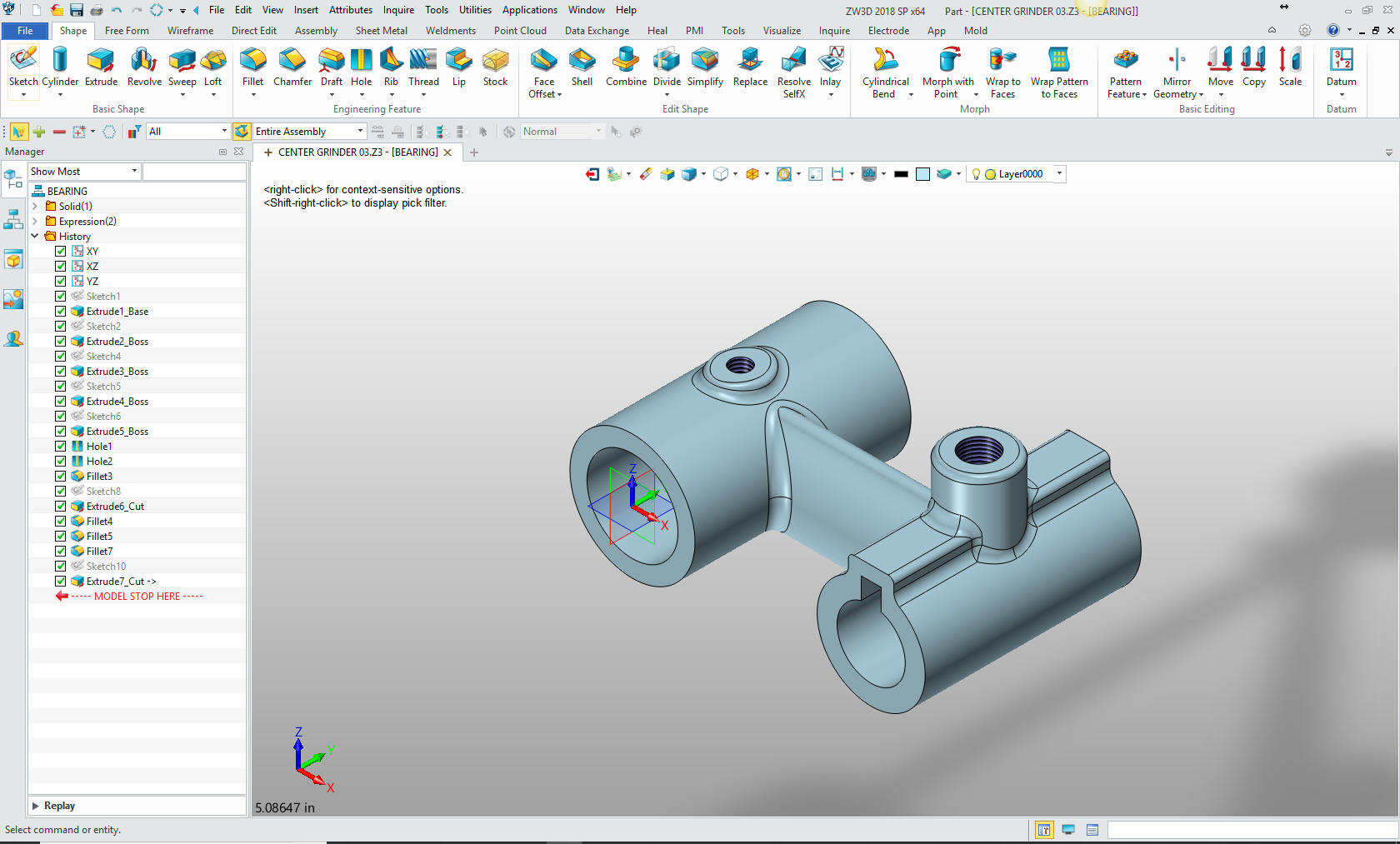
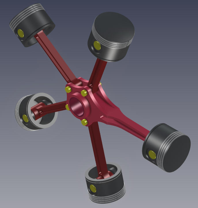
truly is a good exercise. I have already created this assembly in ZW3D as a
training exercise. You can see how I did it
3D MCAD Today most MCAD systems are based on the dated Pro/e (Creo) paradigm. It is incredibly problematic. But it is hardly the only MCAD system. I will show you the most to least productive MCAD system paradigms. The Most Productive CAD system paradigm
There are only three system I know with these features, ZW3D being the only one with history based design, robust direct editing and integrated surfacing, both of the others are direct edit only. ZW3D In ZW3D, you have a multi-object environment
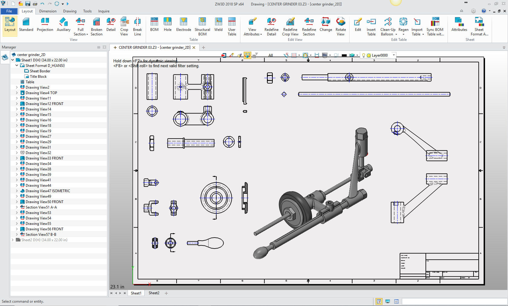
and integrated AID (drawing), which means a
complete project can be done in a single file. Let me show you.
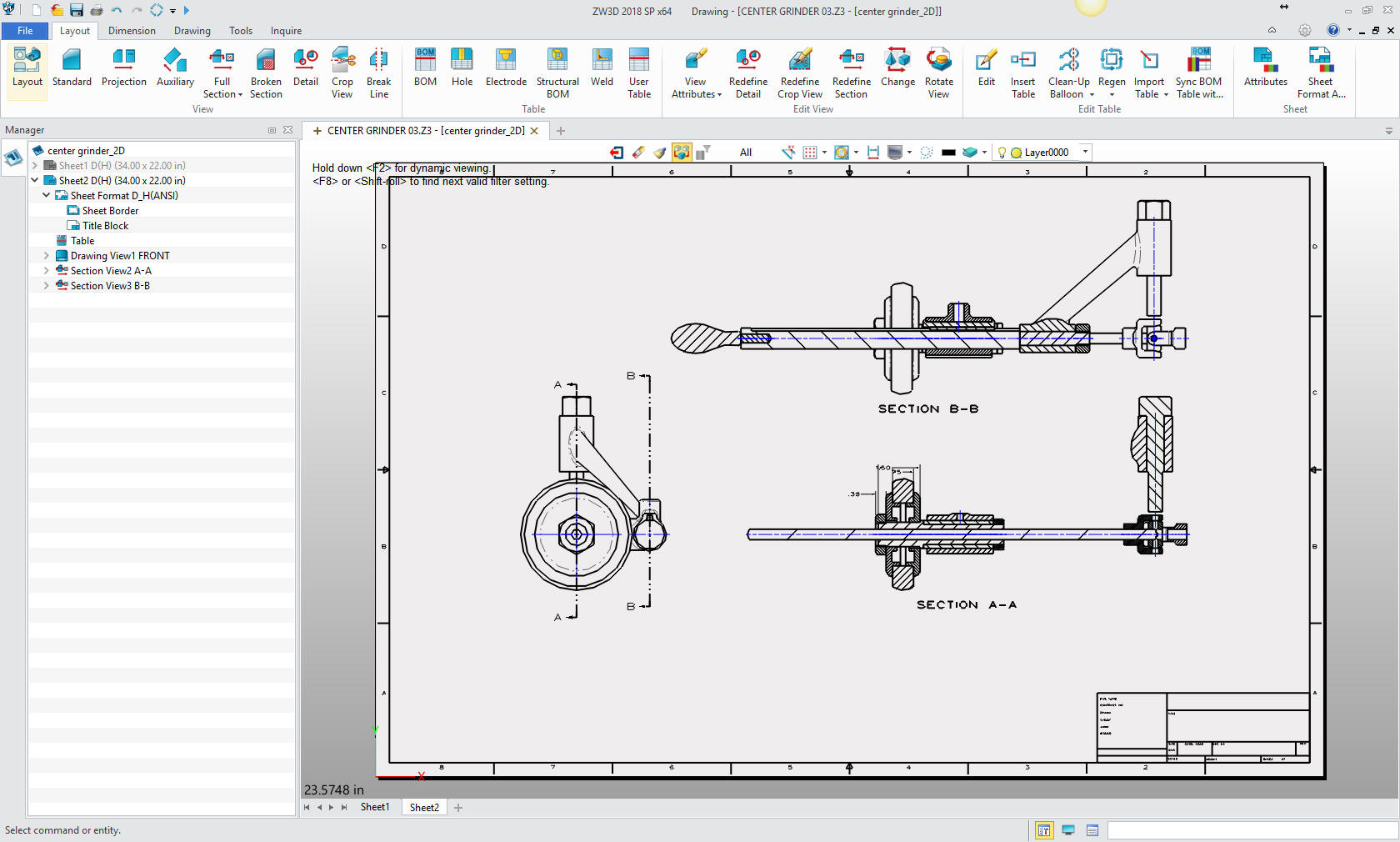
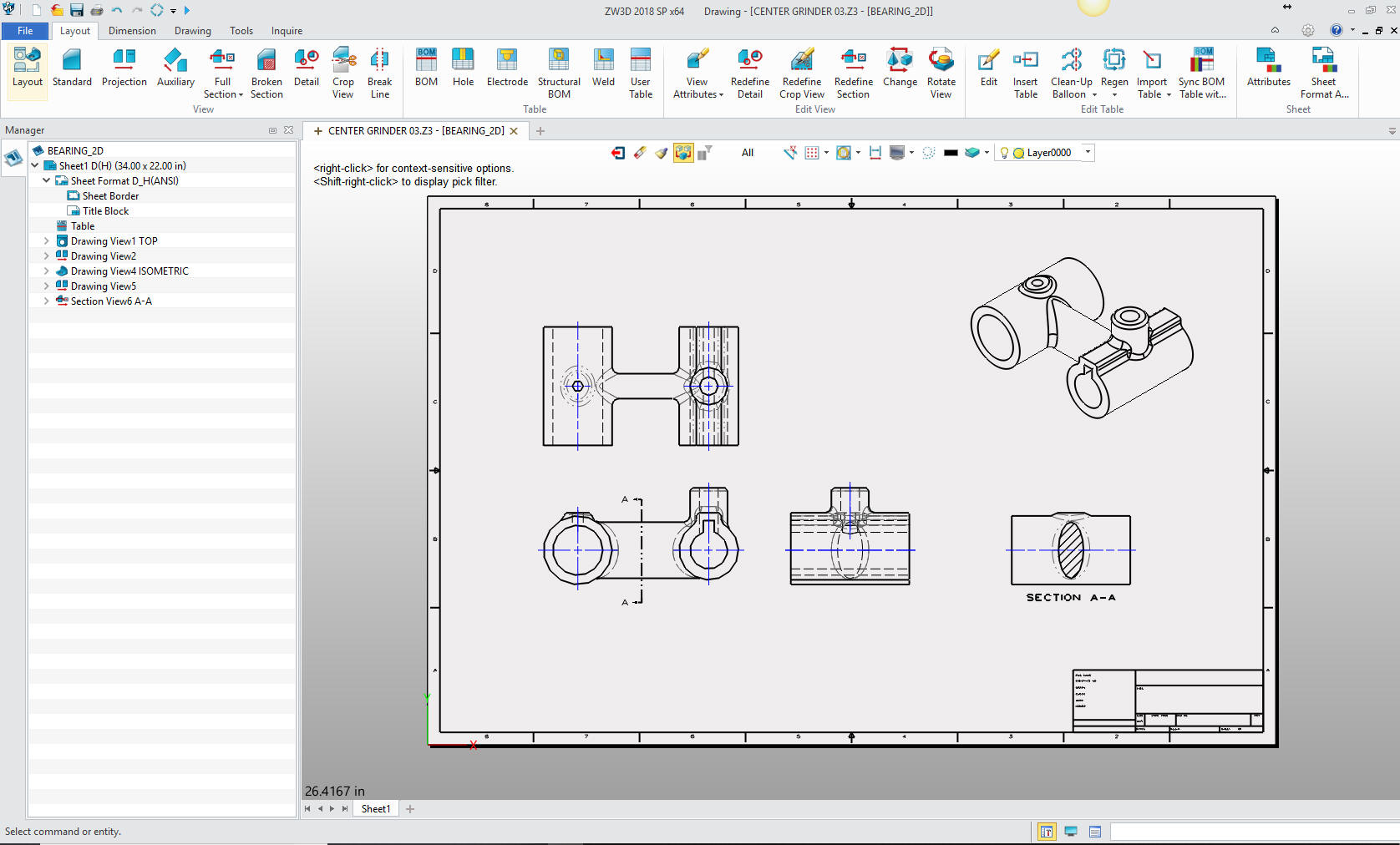
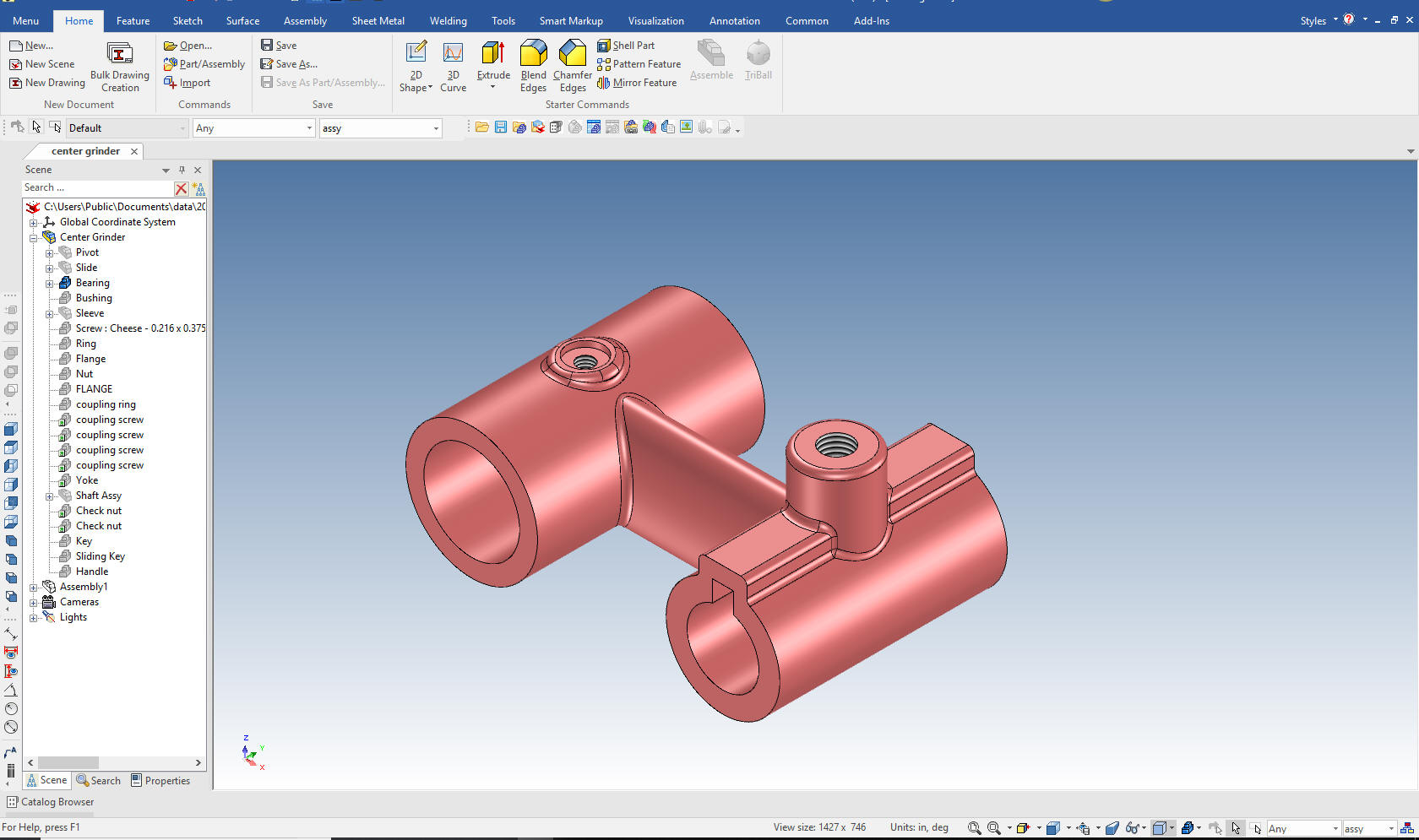
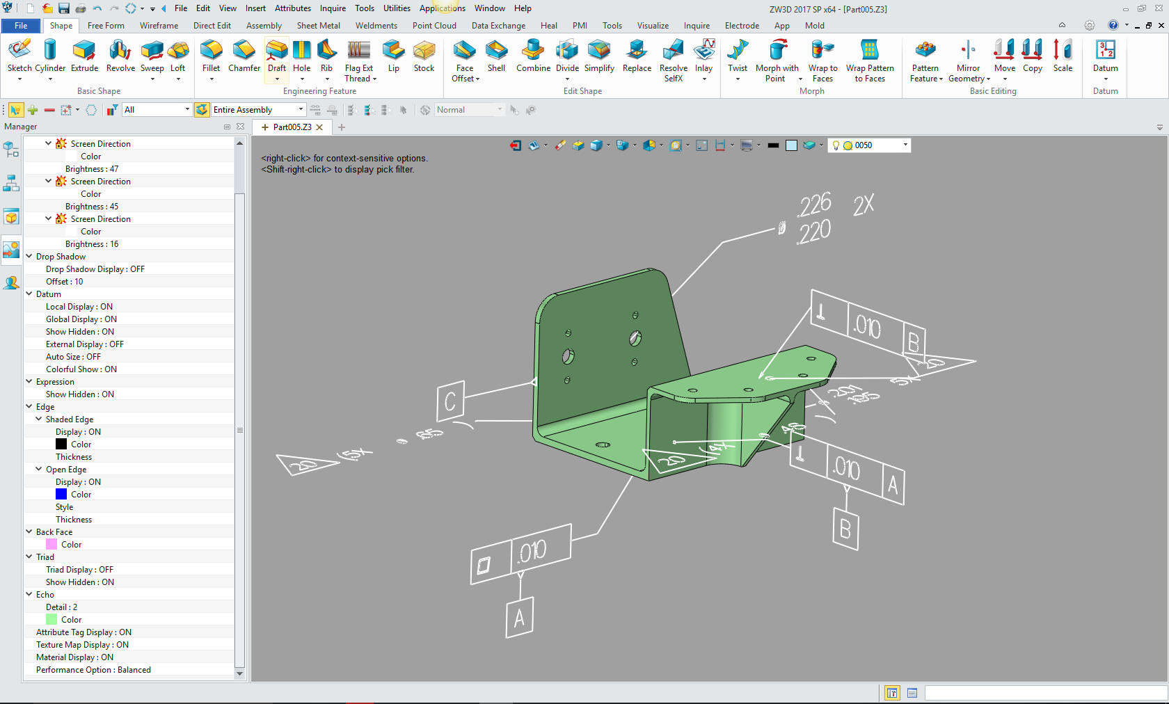
We can actually duplicate the Center Grinder detail assembly with ZW3D. We go to the assembly and select 2D sheet.
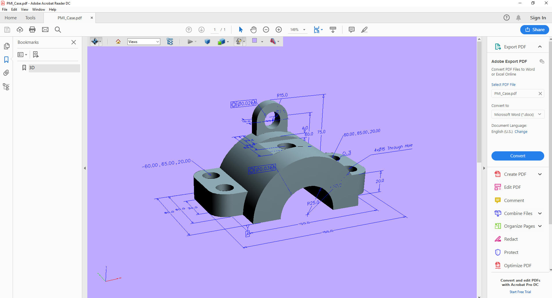
ZW3D vs Catia Lesson 3 Assembly Engineering deliverables 3D Model (STEP or other Neutral Format) with AID The native 3D Model as a PMI. The problem with PMI there is no viable standard export format. ZW3D solves this problem by offering the PMI included in a 3D PDF.
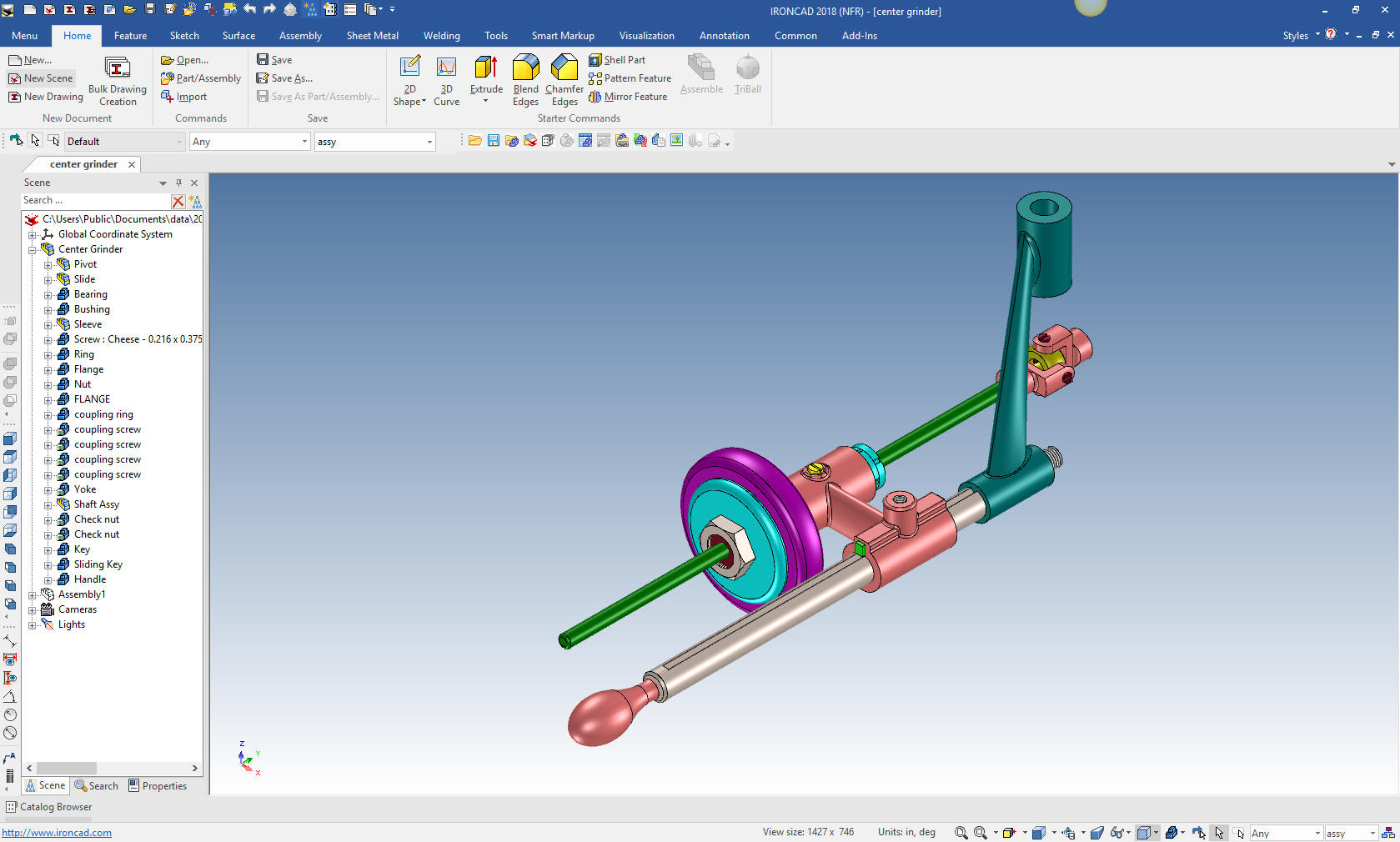
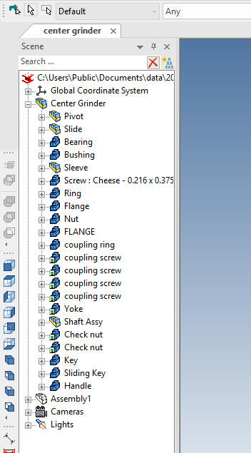
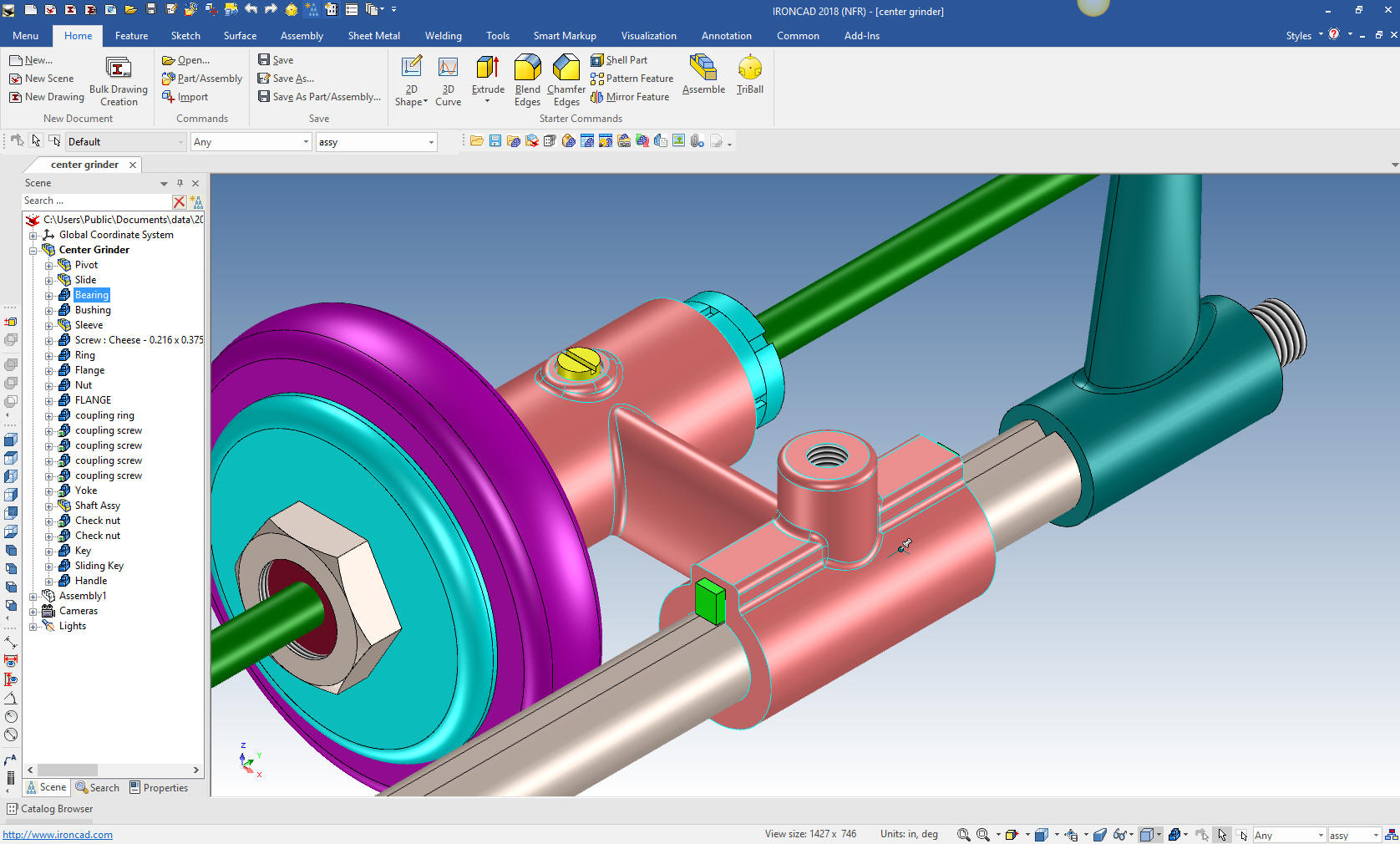
The Second most productive MCAD system Paradigm The next most productive system is the Single model environment with external AIDs (drawings). It is no accident that TECH-NET sells these two packages. We used to sell CADKEY which was also a single model environment. But it was a direct edit only package. I feel history based design is mandatory for a completely functional 3D MCAD SYSTEM. I think IronCAD is the only system that meets this criteria. IronCAD
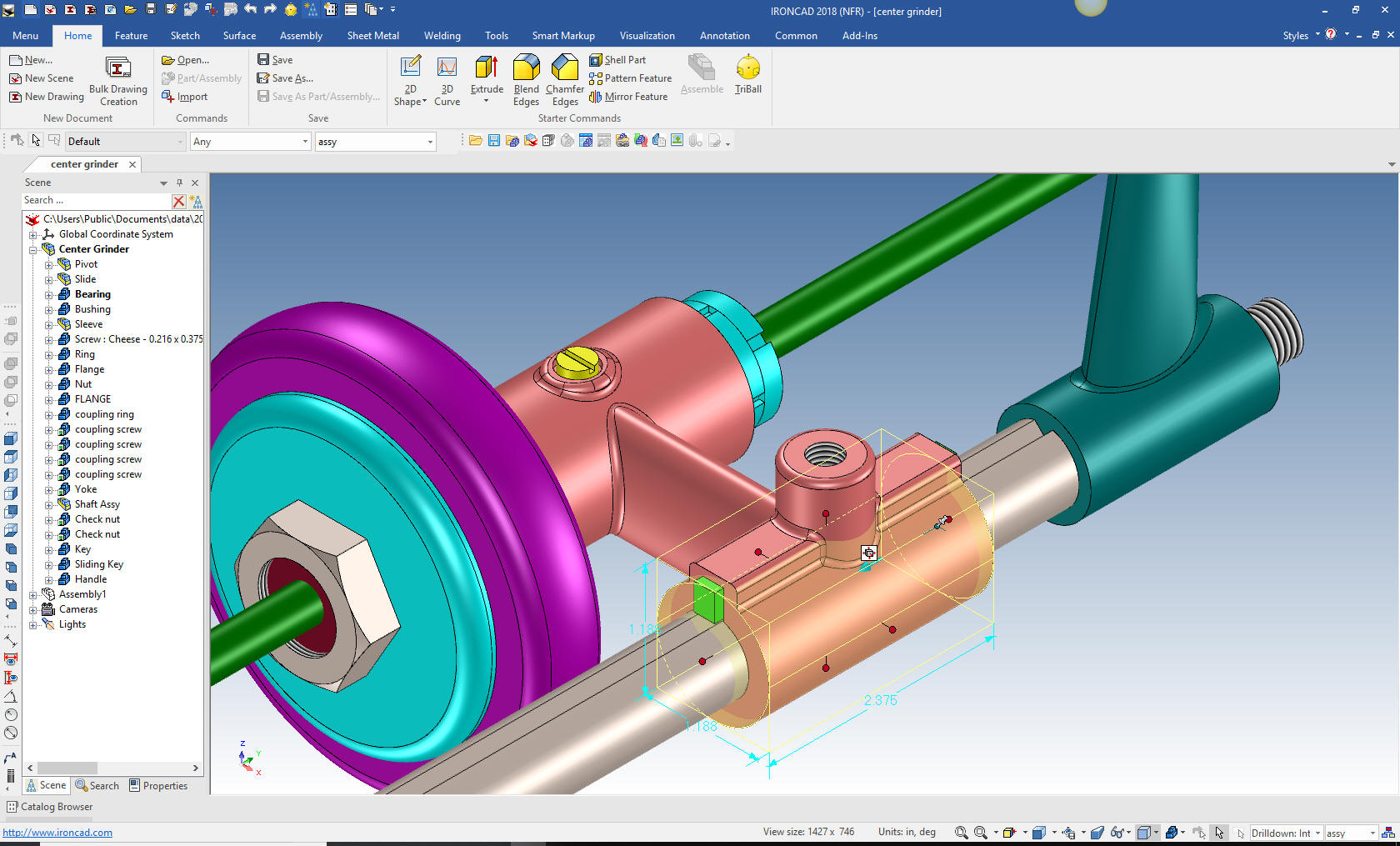
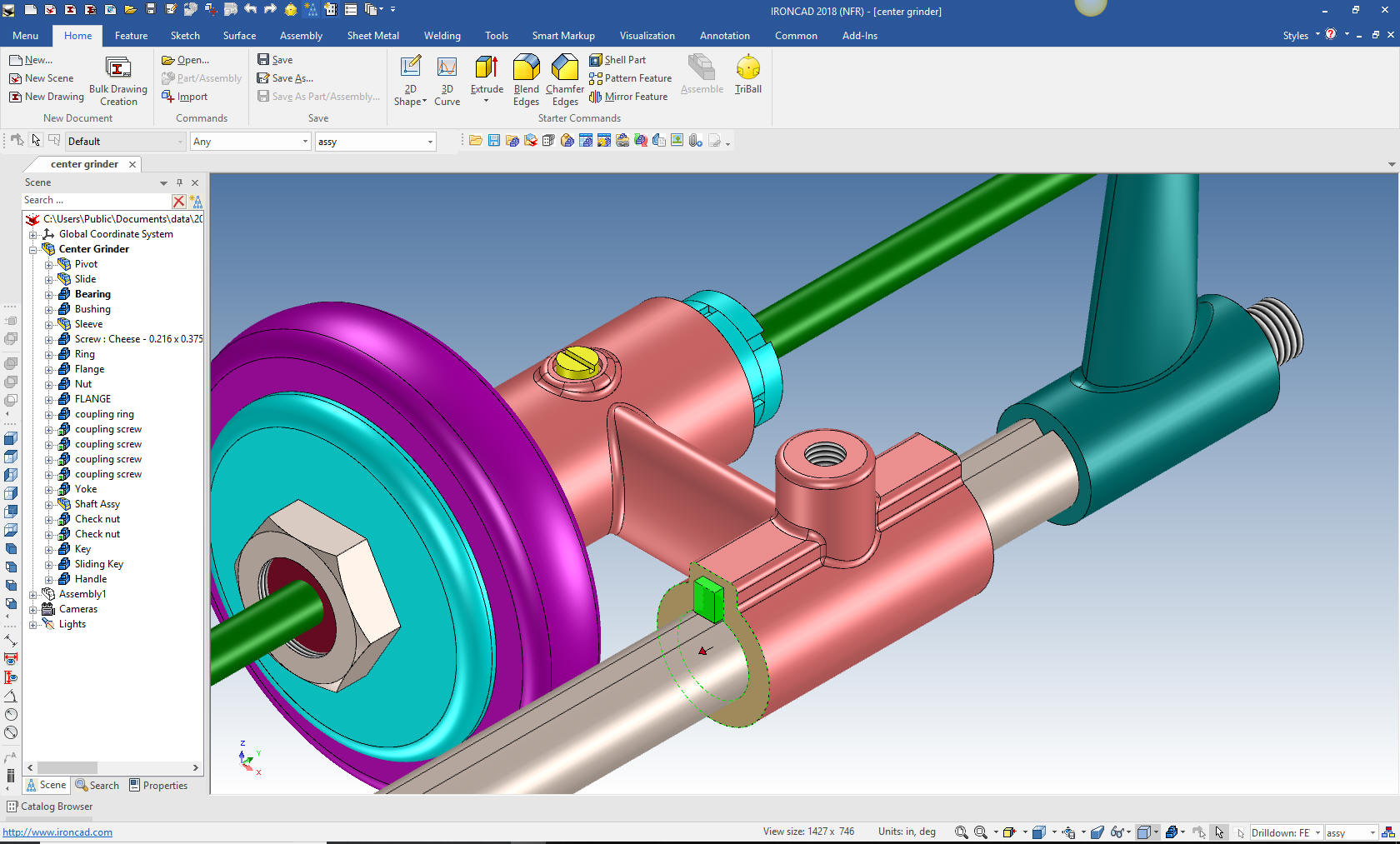
One more click and I am at the face or surface level where I can directly edit the part. You can see the small handle to pull the face. You can also move the face with the Triball.
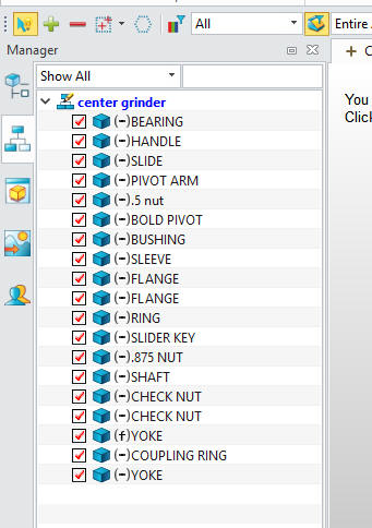
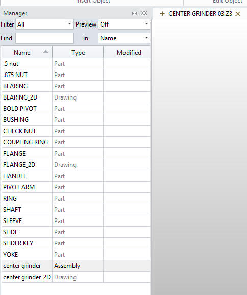
Being a single model environment you have to have a way of separating the parts and sub-assemblies. If you look to the lower right corner you will see a "assy". This is where you set the configurations, this is set for the top assembly.
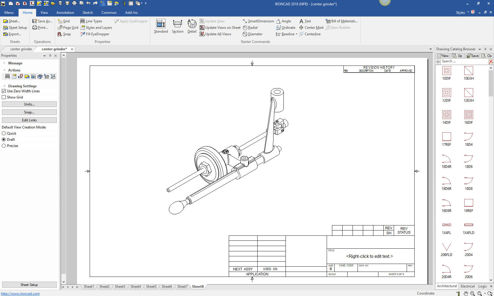
Let's take a look at the assembly AID (drawing). Ironcad has a separate AID (drawing). You can see at the bottom that it is shown in a separate tab. You can have separate standalone AIDs for parts and sub-assemblies tied to the same assembly. But it is best to have them in one AID file. While this is better than the Solidworks clones it still takes a bit of management. We usually have the model and the AID (drawing) files in the same folder. Much simpler than having parts buttered all over the hard drive or network.
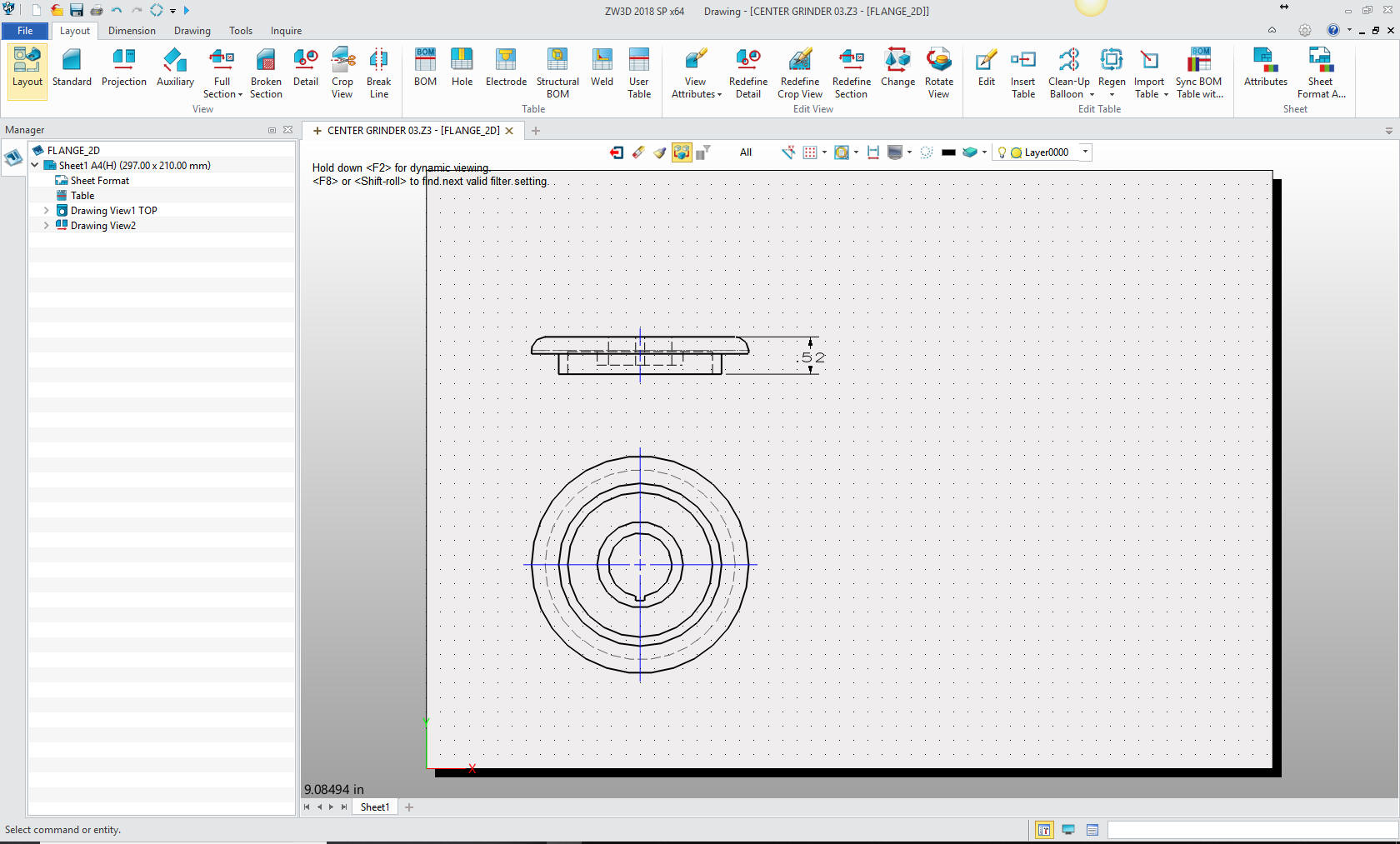
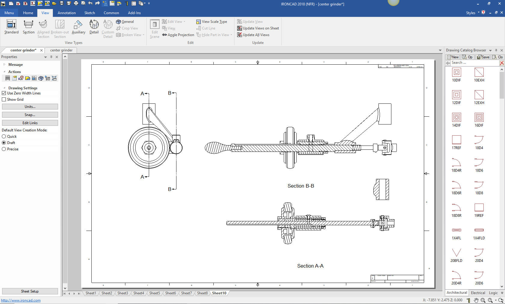
Here we have a multiple parts on the same AID (drawing)
While in the AID you right click on any view an you will be taken to that part in that orientation. In this case we will select the Yoke.
While this is not as effective as ZW3D with its integrated AID, there are many things that give IronCAD a unique advantage. I believe IronCAD is the very best conceptual design package increasing modeling productivity 5X with new design and 10X with modifications. Five Functions that Increase 3D CAD Productivity!! Is 3D CAD Productivity an Oxymoron?
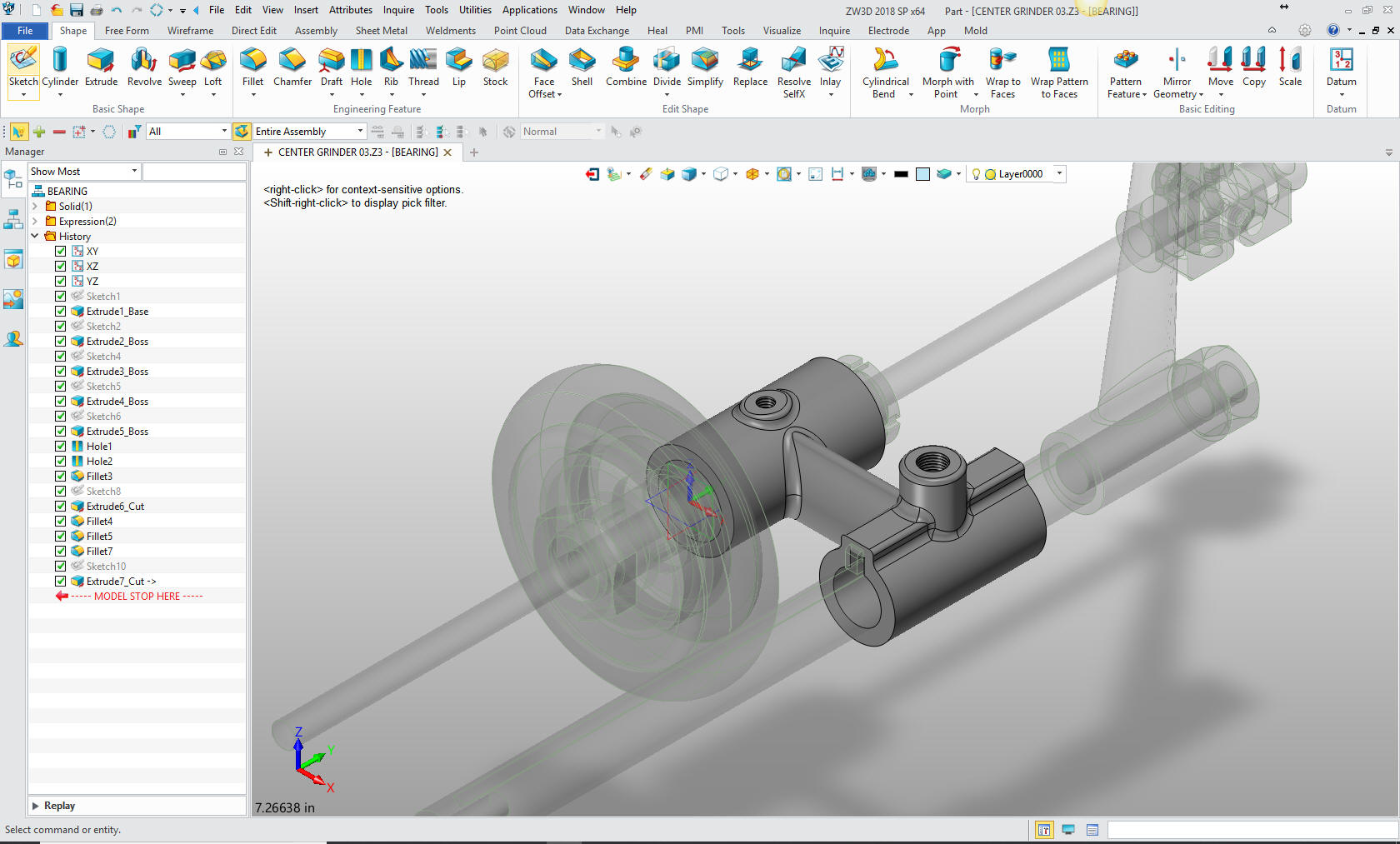
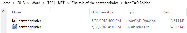
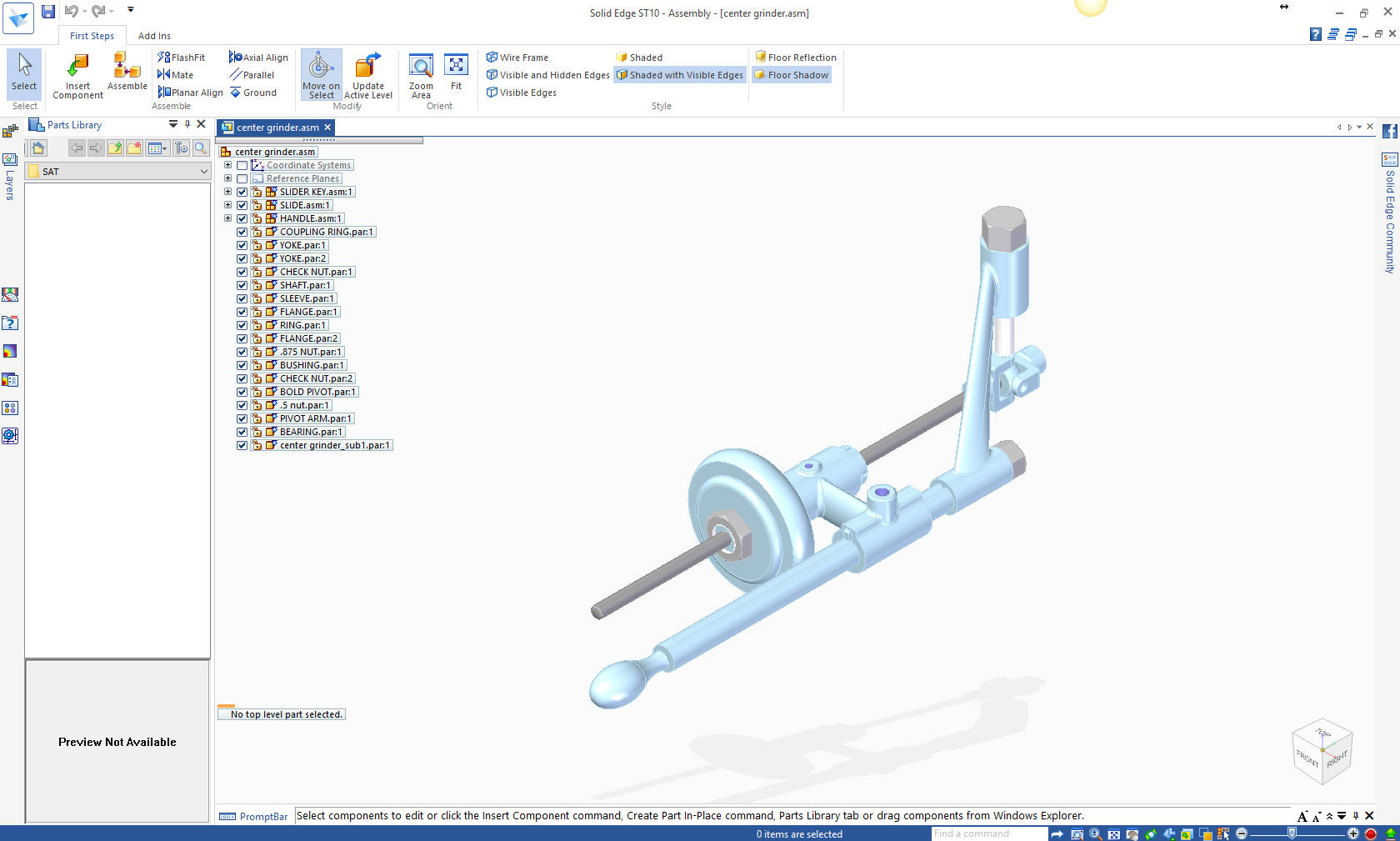
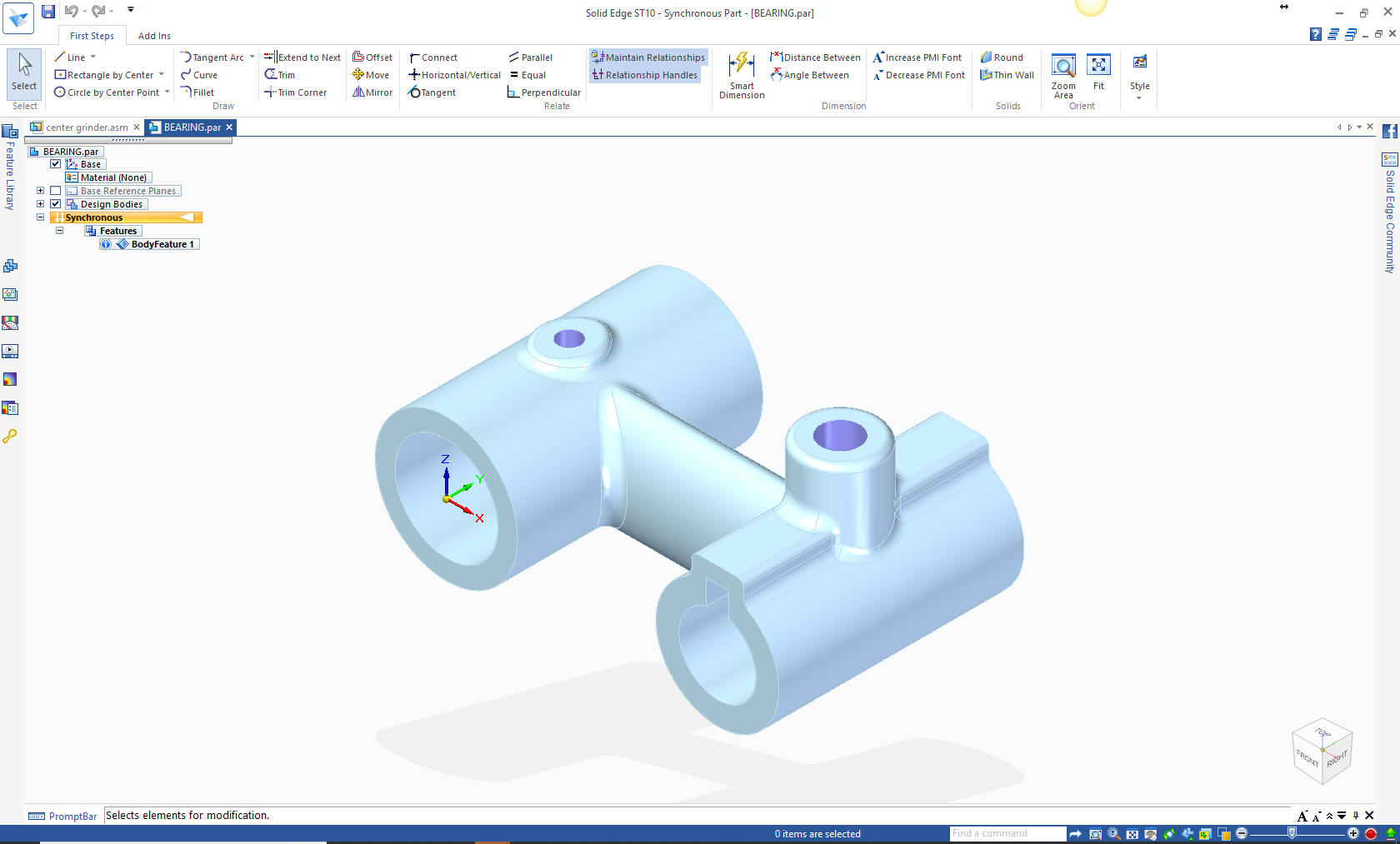
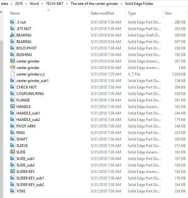
Engineering deliverables 3D Model (STEP or other Neutral Format) with AID The native 3D Model as a PMI. Problem with PMI there is no viable standard export format. You would have to have a seat of IronCAD to be compatible. There is no one perfect CAD package. But then I use 3 different CAD systems and not one of them is a Pro/e (Creo) clone. I do believe you can model in any package and you could actually use ZW3D as an accumulator (a better word than assembly) due to its integrated AID (drawing). With its robust direct edit and integrated surfacing you can modify most any part and the AID (drawing) will reflect that changes. The Pro/e (Creo) Clone This includes Solidworks, Catia 5, NX, Solid Edge and Inventor. I do have access to Solid Edge ST Solid Edge is a marginal Pro/e (Creo) clone. It claims to have integrated history/direct edit but it still bases most of the modeling on history. I have to say it is quite bizarre. The high end systems are not only out of range pricewise, but with the focus on PLM are overly complex for any smaller company, truth be told, they are actually too complex for larger companies also. Here is the Center Grinder imported into SE from a parasolid file generated in ZW3D. Everything comes in fine. All of the parts and sub-assemblies come in as separate files on the hard drive.
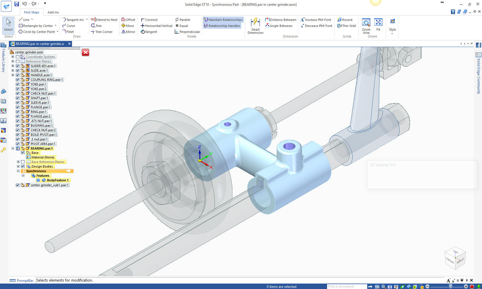
Here is the bearing with the "edit in place" option. It is very similar to ZW3D and conducive to top down design.
Here is the the bearing opened in a separate file.
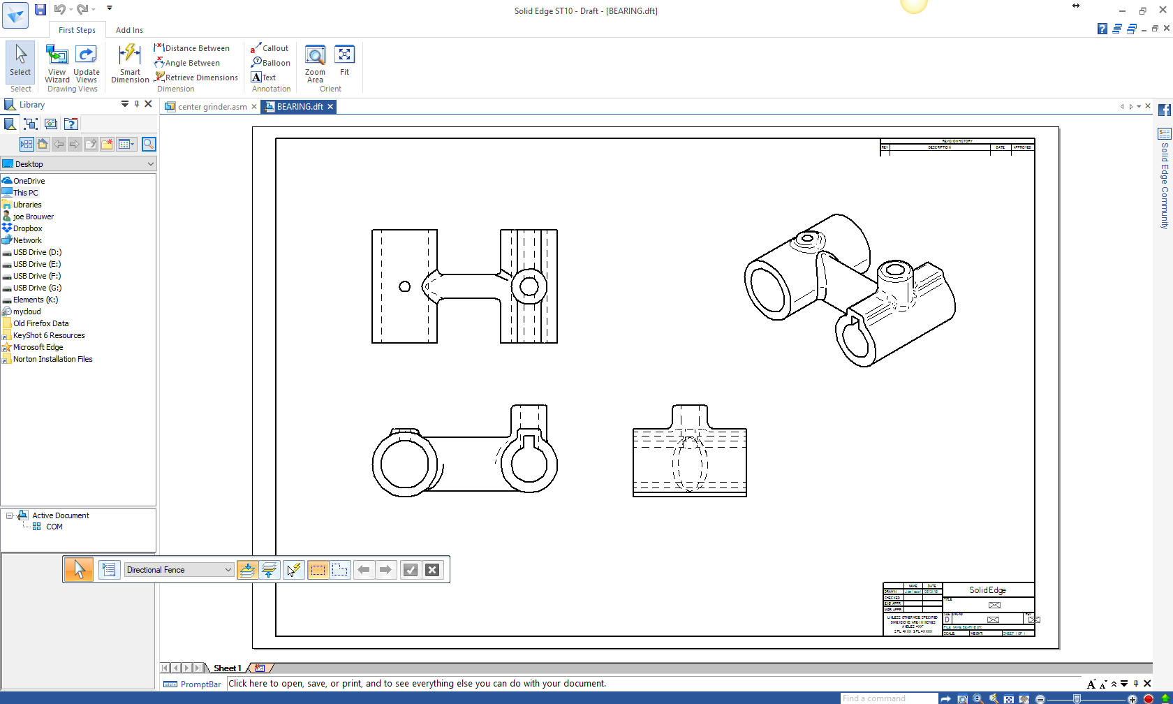
Here is the AID of the bearing. This is another separate file.
Can you do effective work in a Pro/e Clone? Of course! I could create more AIDs and add to the file count but you get the idea. This assembly has 19 parts and a couple of sub-assemblies. Add an AID (drawing) for every sub-assembly and part and you are maintaining 40 plus files. Is there any wonder why PLM is failing and why the unworkable PMI is an option. There truly is no way out of this PLM mess as long as we are basing our engineering on the dated Pro/e MCAD paradigm. I have given you two solutions that would make PDM almost not a problem. Now I suggest we take the Model and AID out of the CAD system and deliver them as engineering documentation maintained as a separate document control system. This alone would eliminate the problem that PLM has created. This would also allow engineers to get back to engineering and, of course, documentation creation, release and maintenance.
This would be the same for Catia, Creo, NX, Solidworks and Inventor.
IronCAD vs Catia Lesson 3 Assembly ZW3D vs Catia Lesson 3 AssemblyEngineering Deliverables 3D Model (Native or other Neutral Format) with AID Now I don't know how these Pro/e (Creo) clones store the part and AID file. Can they be stored in their own folders? Or are they like this assembly? If they are in their own folders how do you assure they are correctly linked to the assembly file? Here is a video showing IronCAD vs Solid Edge with Direct Editing!
The native 3D Model as a PMI. Problem with PMI there is no viable standard export format. You would have to have a seat of the native software to be truly compatible. This is an actual production Catia PMI from Bombardier. Please take a look at this article and see the lack of standards in this format. You can see they are making up the required information on the fly. Quite a mess.
At this time there is no standard "free" PMI reader. The reason is the the PMI is a native file. Boeing demands the use of the 3D native model as the design authority. Compare and Validation Programs? Band-Aids for Self Inflicted Wounds!
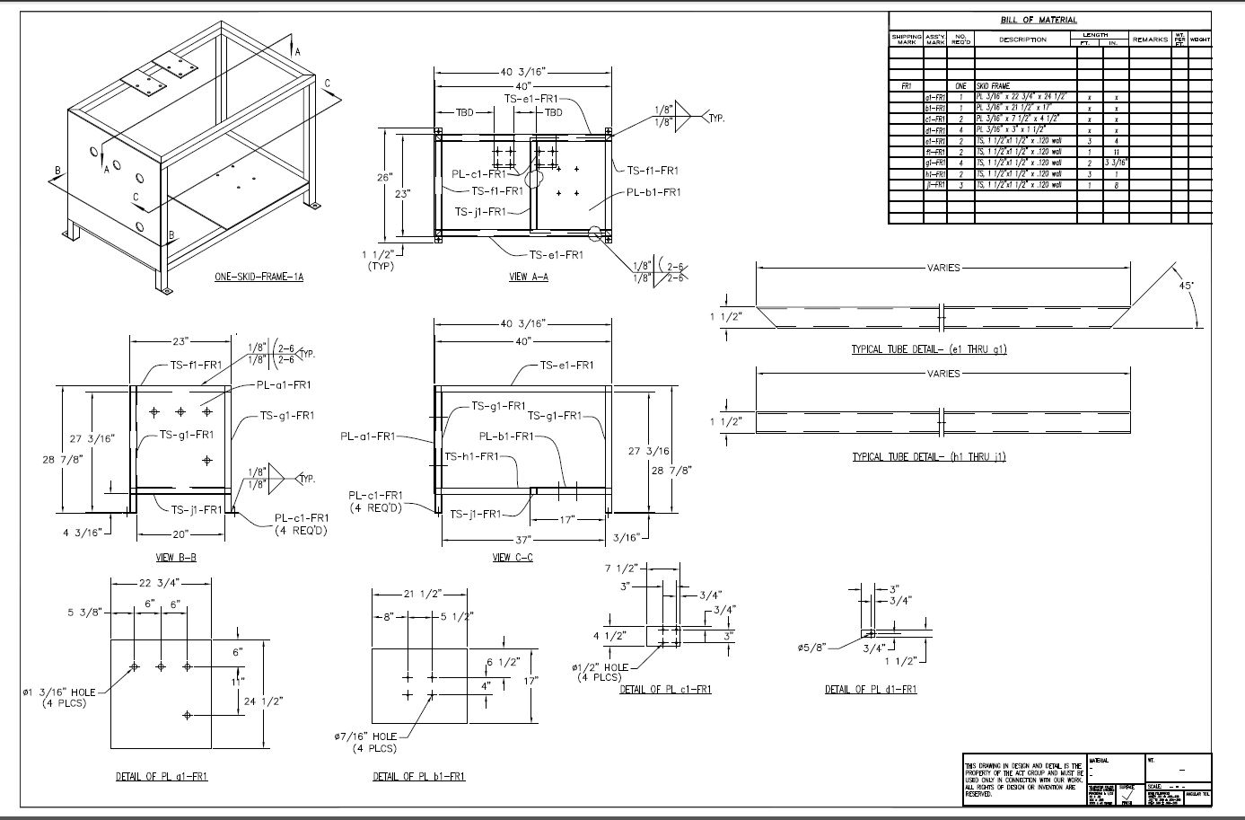
Adobe Acrobat Pro 3D was released in 2007 to provide a common solution would read the PMI (Catia 5 at the time) and deliver the 3D model as STEP and the PMI. I was involved with this product and was very enthused to provide it to my Boeing suppliers. But Adobe discontinued the product, forcing the suppliers to purchase Catia 5. There was no other way to view the PMI for years. Today there are translators the can view the PMI. But remember they are trying to keep up to day with four CAD systems that are releasing different versions every year. There as been a study to use a STEP file as a PMI deliverable. But again we bump into the fact that these systems are releasing a new version every year. Here is a study done by, you guessed it, no one with any direct engineering or documentation knowledge or experience. I have no idea how InfoTechs think they can solve a problem they have never experienced. MBE PMI Validation and Conformance Testing Project ZW3D can import the native files, including PMI, of Solidworks, NX, Catia and Creo. This makes it a viable replacement for these systems. The Manual or Electronic Drawing So you thought I was going to leave this out? Sadly, with machined and sheet metal parts the suppliers are demanding a 3D model. I spent a good part of my career converting drawings to 3D. All You Wanted to Know About Drawing to 3D Conversions Many are still designing many products that are basically fabrications and electronic drawings are fine. I have always used 3D for all my designs. Now, the drawing is not gone. Boeing and all large companies have hundreds of thousands of drawings. From the first Boeing Airplane to the 767. Even the 777 used full detailed AIDs delivered as prints. Only the 787 was designed completely in the Catia 5 system and we know that was a complete fiasco. That was when they still had draftsman carrying much of the load. We see a failure with the 737 MAX, from which Boeing may never recover. Air Force won’t accept any more Boeing tankers until manufacturing process is cleaned upWe will see how it goes with the 797 that will be totally designed by the millennial engineer. Will they have the PLM and MBE system perfected? There was as story about bringing the 757 back. It is designed with drawings. I don't think they have enough millennial engineers that can read a drawing to even get started. I have a couple of applicable stories on drawing conversions and use. Story One I was hired to convert two torpedo propeller drawings to 3D Models. These were drawings of the blade cuts drawn 10X. None of the suppliers had the expertise to even model them. I did one blade of each and rotated and copied. Was not a tough job but far beyond the scope of most machine shops. This was a government job so I can't show the models. Story Two Selling IronCAD, a 3D solution to an AutoCAD electronic drawing user. Some have been stuck in Autocad making drawings. But none are still on the drafting board. A while ago, I gave a presentation of IronCAD to a company that was still using Autocad to make drawings. They built welded assemblies and did not design any machine parts and were satisfied with creating drawings since they were basically doing component design. I actually created the frame assembly in front of them in less than an hour and created the AID's including an ISO view of the assembly within minutes. Showing them the speed of solid modeling.
Here is the original .dwg. As you can see it is a detailed inseparable assembly. Imagine the time to just create the ISO view? Trust me it is in 2D. I did not use the .dwg graphics in creating the model. It was made of square tubing and I just created one tube and copied and pasted them into position and pulled them to the correct length and trimmed if required.
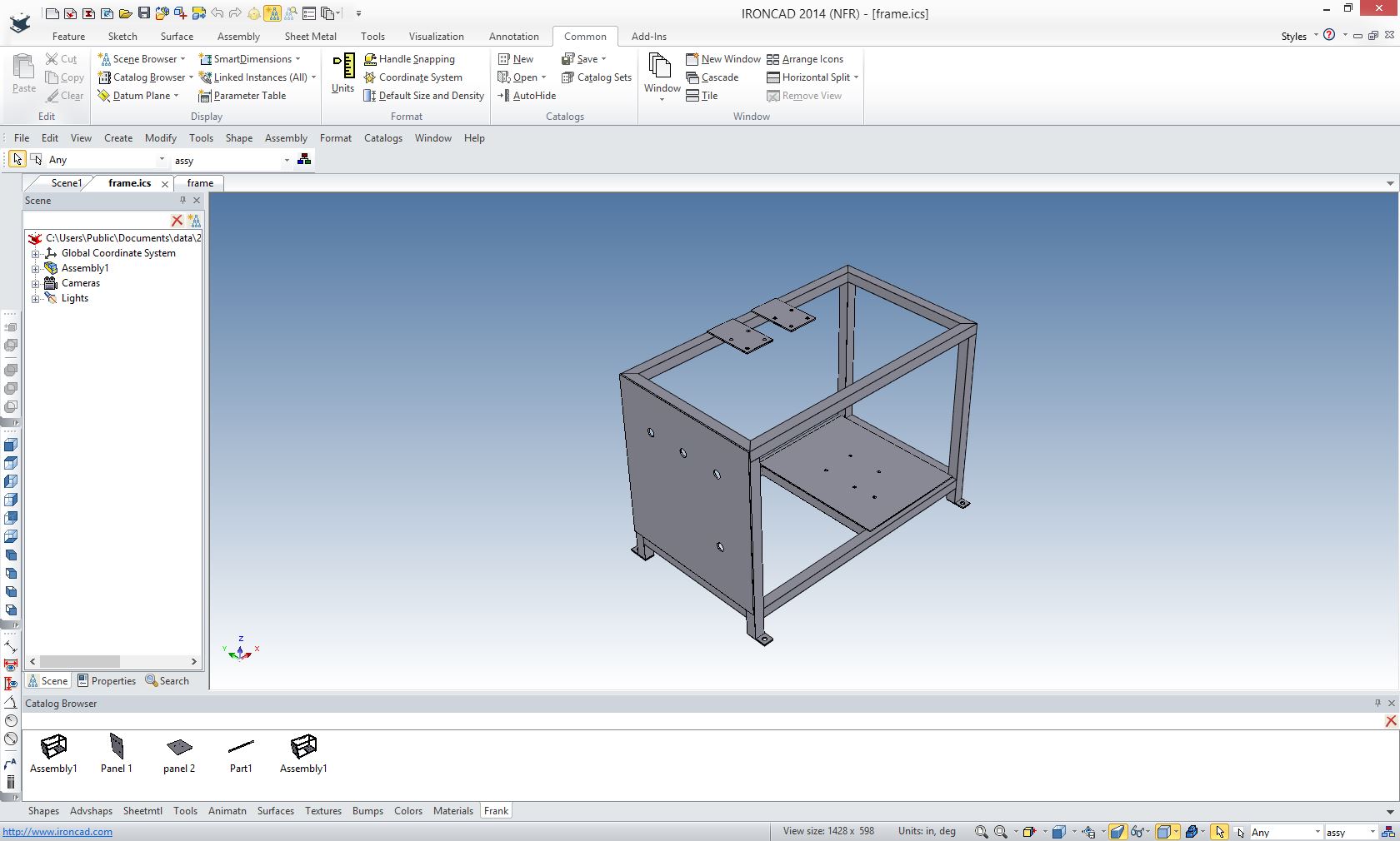
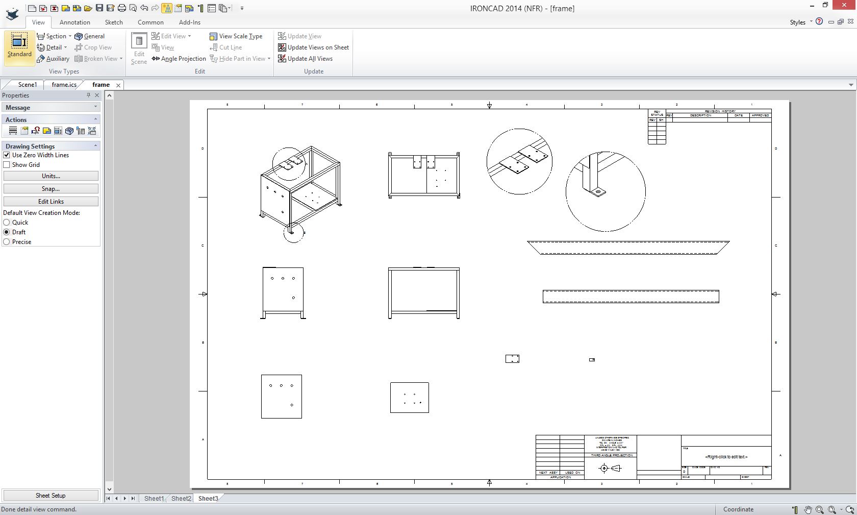
Here is the assembly created in IronCAD. Notice we created a custom catalog (bottom) with some of the common features, parts and assemblies. Imagine this feature available if you design products with common components. It took around an hour.
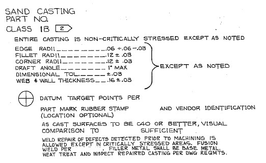
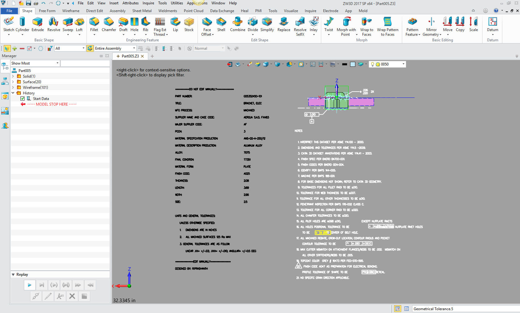
We do not create drawings. It is time for us to quit using the term "2D drawings" that describes a very tedious process that is rarely used in our industry today. Anyway, what other kinds of drawings could they be? Story 3 I was hired to do an evaluation of a machined part from an old customer and associate working for a large machine shop. He called and said a large airplane company sent them a drawing and the 3D modeler was finding cavities in the part. This was after two weeks of modeling in Catia 5. They needed the 3D model to do the CNC programing and then machine it. I am not sure if the company has a contract with these folks to convert the drawing and provide the Catia model or just deliver the final part. You have to wonder if the large aircraft company would inspect it or leave that to the supplier. I assure you all standards are out the window. I asked if it was a sand casting and he didn't know. One look at the drawing.
My associate (20 plus years), the quoting person, the company's purchaser, the manufacturing or engineering professional that initiated the request and who knows how many others, never noticed this was a "Sand Casting"? The 3D modeler didn't notice the significance and he had been working on it for 2 weeks. They had to call a person they knew had the expertise and one look saw the problem by just looking at the drawing? Wow, am I worth my money! The drawing consisted of the sand casting and the machining of the casting. No one questioned these two separate definitions? This large aircraft company is a leader in Model Based Enterprise! The model is the design authority!
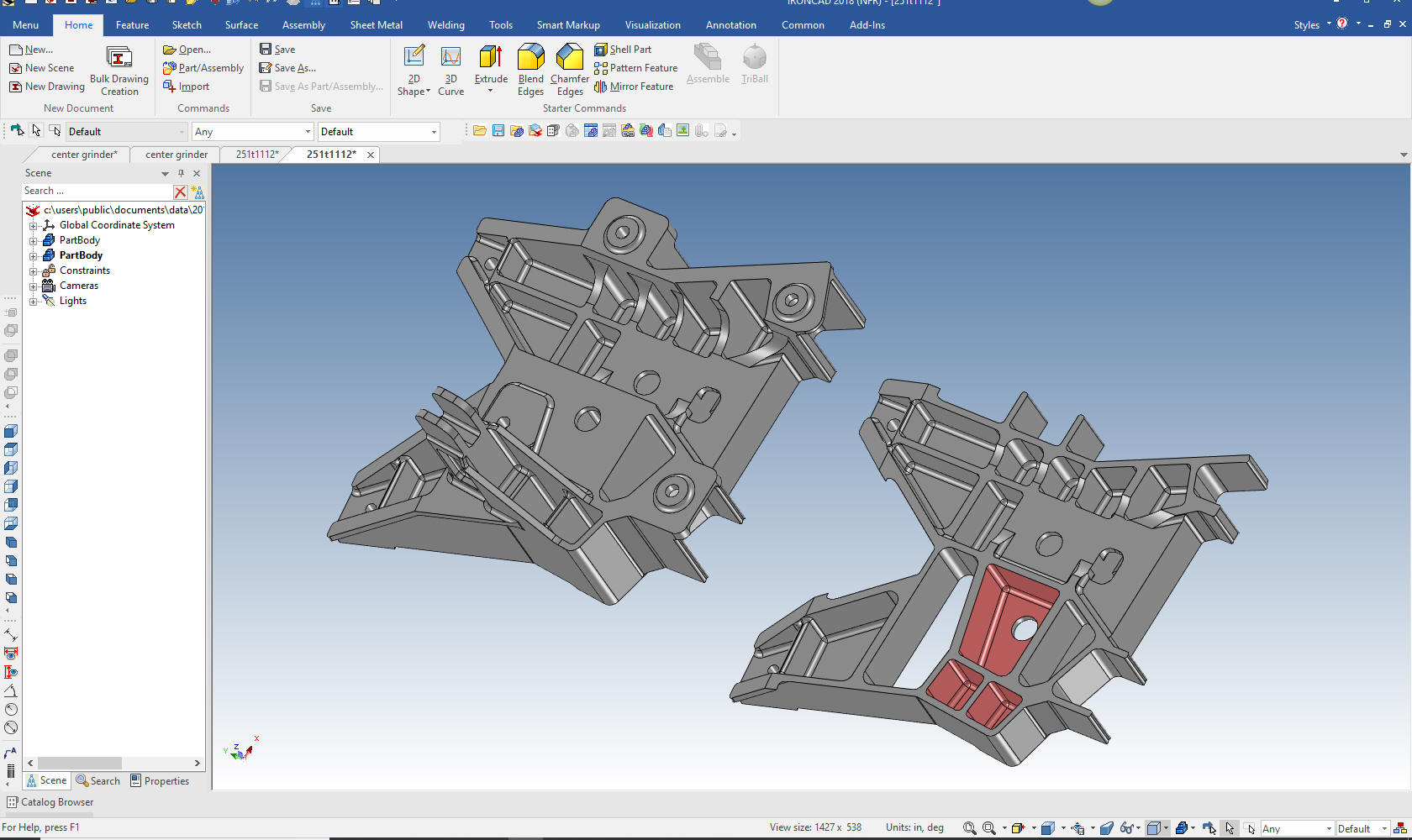
Can the 3D Model Be Used as the Design Authority? Why in the world are they sending out drawings? You would think the company would have a department with a "Standard Process" dedicated to convert drawings to 3D models in Catia to assure they were meeting the model as the design authority. I am sure this would be a great place to put the millennial engineer to get familiar with the form, fit and function of airplane parts and documentation. It is interesting that the supplier is now required to provide the model. But at what cost? This two day model turned into weeks, maybe a month? Now they have to provide the model, which I saw was done incorrectly. First, they have to check that the model matches the drawing, which it doesn't, then they have to inspect to the model. Uh, who is in charge of this mess? Why does this company depend on the supplier to provide the 3D model in Catia? We can only speculate. But again I note, that they obviously have no standard processes in place. Using the native Catia 5 file, I imported the model in IronCAD and found the cavities. You can see them here in the sectioned view on the right. But I also instantly saw the part was done incorrectly. The errors stood out like a sore thumb. You have to go through a thorough checking when you convert drawings to 3D models. So two weeks already spent. Corrections another week. Checking another week. How many more hours will it take? It took me less than 30 minutes to define the problem. If you need a checker or an highly experienced design draftsman to sort out problems, give me a call!
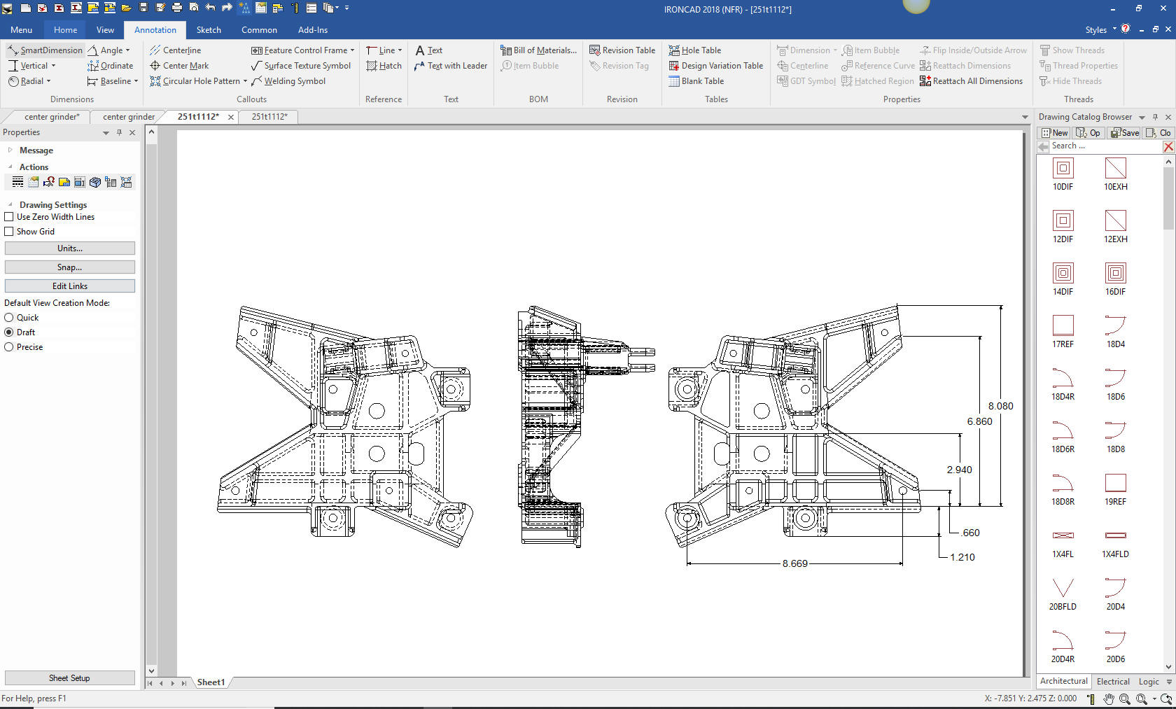
Drawing conversions are much different than designing parts. You have to re-detail the part exactly to check it. There are no short cuts. Murphy is looking to play a big part in this process. Here is an AID (drawing) in IronCAD checking the part and with just a few dimensions I found a serious modeling error. You can see this is a very complex part.
Good afternoon Joe,
I read through several of your articles/blogs and found it to be very
interesting. For our company, I’m asking if you could offer a
suggestion or better solution to our requirements. We currently have a
seat of Catia V5 to look at .catpart files for quote and I also use it to
make paper drawings from the models of parts that we currently make.
787 parts mainly. This is expensive software as you know, and it’s
what were led to believe was the best solution for moving forward in the MBD
environment.
Our shop prefers parts lists and paper drawings. Maybe it’s
antiquated thinking, but it still works best for us. Is ZW3D software
a good alternative for getting the required information from a Catia V5
model to make a paper drawing and parts list? Sometimes we do get an
EPL or BEPL with the notes, flag notes, etc extracted out already, but not
always.
I’m sure you all well aware of what I’m talking about and asking. We
are a Boeing subcontractor but since being bought by the XXX group, we now
do other aerospace work as well, Airbus, Bombardier, etc. Our parent
company is based in France so I’m hoping a move away from Dassault won’t be
frowned upon😊 Any advice or help in a better direction
would be much appreciated. It’s been some time but we used to buy
Cadkey from you years ago. Thank you,
The 1990's - 3D CAD/CAM Moves to the PC!!
PLM,
The workable standards of the past have given away to the most convoluted mishmash of non-connected processes. It cannot go on like this. Yes, it is getting parts made but at what cost? The first twelve 787s were not deliverable! Boeing couldn't afford a full size mockup they so effectively used as a standard process in the past? They used actual airplanes that were to be delivered as test beds. I am sure the mockup looks cheap today. They said no more mockups with the 777, they could do it virtually, LOL. This was probably the first decision made by those without the knowledge of the past, now thinking the 3D model could do it all. They didn't create a mockup, just model verifications. A rose is a rose by any other name. So many are fooling themselves and so many others. Yes, it is out of ignorance of the past standard processes. Boeing used the first two 787 for mockups since they never flew! Nope, no AIDs!
The A380 had to completely redesign its cabling system, they were too short. What did they blame? Using two different totally incompatible system Catia 4 and Catia 5. Think that one through! Only the French would give the same name to two totally incompatible MCAD programs. We need a real disruption!! Where do we start.
Leave manufacturing alone to do their job. They did it before! There you go! How much cost savings? Think about having Dassault, Siemens, Autodesk and PTC out of your lives. Just by changing to a much more functional cost effective 3D MCAD system paradigm would eliminate much of the dependency on the CAD system. Depending on the size of the company this could be millions a year. Most of you have been stuck with the limitations of a system for decades, suffering under their constant upgrades to keep you paying. You could cut this overhead by 75%! The Worst to Best 3D MCAD Systems Expanded! Okay, let's not do what we did in the past and throw your complete engineering into the hands of another CAD company. We need to develop a industry standard. No, I have already showed you that we cannot use any of the popular CAD systems. Yes, I know you have may have lots of money invested. But the legacy data is not lost. ZW3D can access all of the modeling including PMI directly. But we can have the AID as a PDF. We can have a smooth transition by implementing a cloud based document control system. But we can start small with ZW3D as the program. We can do a couple of small projects and see how it works. Which one of you large companies are willing to invest? Give me a call. It would be nice to have representation from the government, academia and from each of the major industries get involved. But I only want engineering personnel with hands on experience. Preferably, some professional draftsman of the past with both drawing and 3D CAD experience that find it odd why we are calling a parts list a BOM. I do not want any PLM or MBE genius's, no IT gurus, nothing above a BSME, unless they have a good amount of design and documentation experience. We do not have the cloud based document control system as I envision it at this time. But we could contract some programmers experience in this area, Onshape, GrabCAD or others to provide one. It would take very little programming. There are many cloud based 3D CAD part providers. This is a incredibly simple solution. Go to Onshape to see that it is basically a documentation bucket with a 3D model. But you can have a just single drawing in the form of a PDF available no need for the model. In fact, you can have any file format stored there. Boeing is sending scanned drawings as PDFs by email, imagine if they had their archived drawings available in this system? This opens the door to a much more complete definition of our engineering documentation. Design notes, analysis, revisions, etc all kept up to date by a staff trained to maintain the system. At Pre-Catia 5 Boeing, this was the Document Control Group. For those programming companies that would be interested in developing the optimum Cloud based document control system. I have defined it in these articles. The Embedded Title Block! A PLM Solution!
Who am I? Start here. This the first a in a series of articles that introduces a career defined by the introduction of 3D CAD into industrial/mechanical engineering.
|


TECH-NET ASSOCIATES | RENDERING OF THE MONTH | CAD•CAM SERVICES
HARDWARE | TECH TIPS | EMPLOYMENT | CONTACT