|
Engineering Ignorance Defined III How to Define a 3D PMI Assembly You have got to be Kidding!  | ||||
 Engineering Ignorance Defined CONFUSED? MBE - Model Based Enterprise MBD - Model Based Definition Engineering Ignorance Defined II Top 5 Reasons to Use MBD DEBUNKED!
Engineering Ignorance Defined IV
Engineering Ignorance Defined V I am actually basing the "Engineering Ignorance Defined" Series on articles by Obie Wu! "Oboe Wu is a Solidworks MBD product manager with 20 years of experience in engineering and software. He is an advocate of model-based enterprise (MBE) and smart manufacturing" Solidworks: Engineering 4.0? Solidworks Totally Misunderstands MBD Now I do not like criticizing anyone directly, but as the the manager of Solidworks efforts on MBE he is quite influential. Check out Oboe's profile on Linkedin. There is no experience on engineering documentation. He has never made a drawing, created a 3D model and generated an AID (Associated Information Document (drawing)) or a PMI in a production environment. Never reviewed, approved and released any engineering documentation to document control and to manufacturing. He has made some very incorrect comments on how 3D MCAD is being used. Sadly, there seems to be no one around him that really realizes how Solidworks and the 3D MCAD system has been used for over 36 years. The Death of the Draftsman or “Where has all the talent gone?” Oboe has a MSME and an MBA. Obviously he is very bright, but he groomed himself for management not drafting or even design engineering. Who in the world would put him in charge of engineering documentation? So, who would you look to? A draftsman, of course! Drafting, not engineering, was in charge of engineering documentation. Engineering documentation is in chaos. It is now being defined by those that have absolutely no applicable knowledge. Don't believe me? This is one of the most shocking surveys on how out of control our design and documentation is. Engineering Documentation Today! I am available for consulting to help align the MBD and other documentation efforts of Solidworks or anyone else with today's engineering workaday world. Even though I an not a fan of Solidworks or any of the Pro/e (Creo) clones they can be used in a much simpler and more productive documentation standard that could eliminate PLM. Any company could lead the way by establishing a new document controls system. There is huge profits by being the first to develop it. Joe Brouwer 206-842-0360
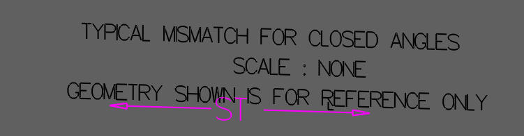
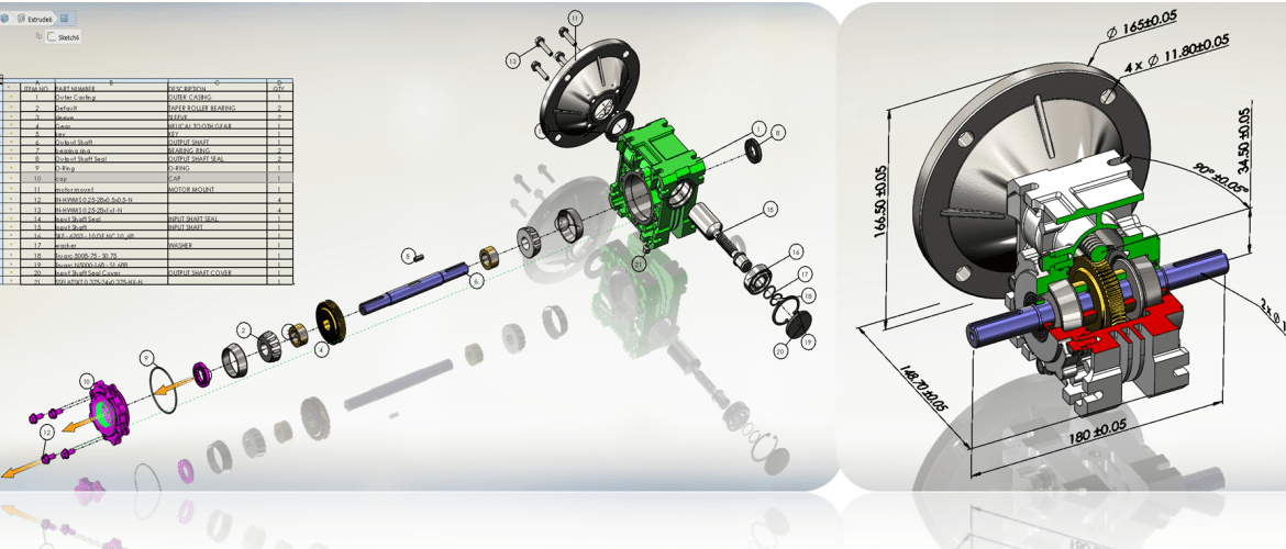
How to Present the MBD Data of a Gear Box Assembly How to Define 3D PMI in a Gear Box PMI Cannot be used as an Assembly Document! We first have to ask this question. Why was PMI (Product Manufacturing Information) created? PMI is to replace the model and AID (Associated Information Document) as a single file. No, we do not make drawings in 3D CAD and never have since I was introduced to CADDS 4 in 1982. The ignorance of calling anything that looks similar to a drawing a "2D Drawing" is beyond belief! PMI is the ugly step child of MBE (Model Based Enterprise) or is it MBD (Model Based Definition)? No one really knows! This concept was so amateurishly developed and poorly implemented that it is already an incredibly costly quagmire. But lots of heads are going to roll if this doesn't work. So PLM/MBE promoters will continue to walk down the streets naked until someone yells!!! "Good God! They have no clothes." Why MBE/MBD/PMI Will FAIL Why MBE/MBD/PMI Will FAIL Part II A PMI is what you can only call a 3D presentation with minimized GD&T and annotation in 3D space. It seems like GD&T is the only tolerancing allowed because it has the Profile Tolerance Frames on every surface. This is an incredible bastardization of a viable tolerancing system. It was never design to be utilized in this manor. This article shows the PMI is not and can never be a viable engineering documentation format. PMI vs AID In the below image there are no profile tolerances. Why? They have plus or minus UOS (Unless Otherwise Specified) tolerances in the notes. "THE NOTES? Plus or minus to what? I know, I know.. you have no idea plus or minus off what face? This is a released part from a large airplane manufacturing company. Don't blame them, those that have defined this idiotic process have never done one real applicable job. The users are just trying to make it work since there is no standard. This part is also a inseparable assembly. It has nutplates called out, where you might ask? They are referenced in the notes, of course. Only a seasoned draftsman would roll his eyes. Not one PLM/MBE guru would even notice. I wonder where the nutplates are installed is it a new part number? Even those of you that have never done any engineering documentation can see the problem. In a standard system of the past you would have an inseparable assembly. The machined part would be -2 and with the nutplates would be -1. 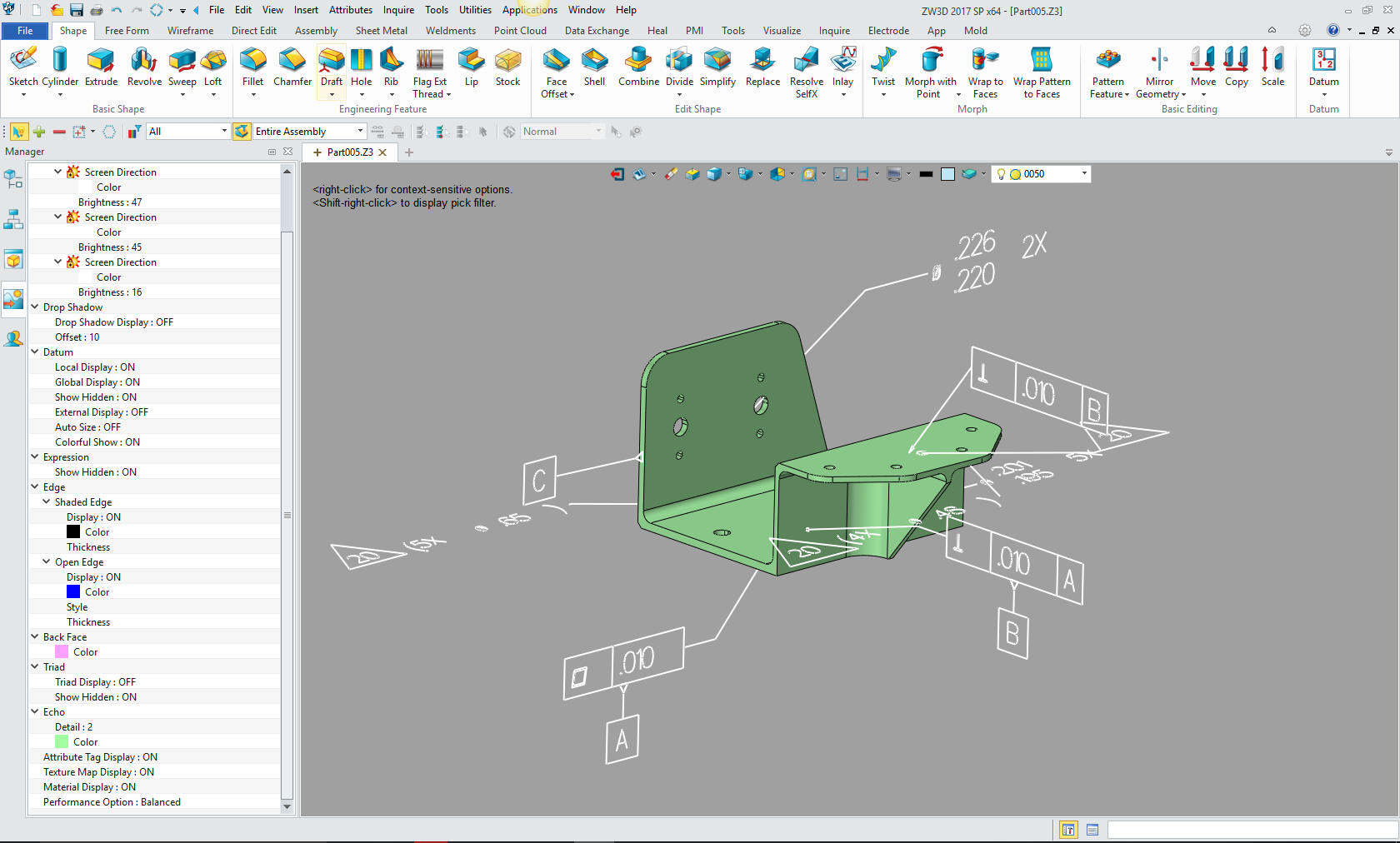 Here is an AID of this part. And I guarantee you it would be much simpler to create. It is a format that can be printed for review and checking. What is required. Yes, an Adobe Reader. How much does an Adobe Reader cost? In the PMI below, what if they sent out the AID as a PDF and the 3D model in a neutral format, which is was the programmer got anyway. The cost? Nothing! The fellow had a compatible CAD/CAM system. Is there anyone out that even understand the cost of MBE/MBD/PMI? Not that anyone wants too, obviously. There is even a 3rd party Viewer for quoting minimized PMI that offers dimensioning and markup. Band-Aid after Band-Aid just to attempt to make this failed system work for manufacturing. Quoting Tools: CAD Dimensioning Another Band-Aid for MBE!  Here is another PMI from a large aircraft company. This was sent from an associate and customer. He was looking for a viable PMI reader. At that time ZW3D did not offer PMI compatibility. He had to spend $650.00 for a 3rd party PMI translator just to program this part. He was a contracted by a supplier. So the requirements by the company of validating the native Catia part to the STEP file generated by the translation program was violated. Compare and Validation Programs? Band-Aids for Self Inflicted Wounds!
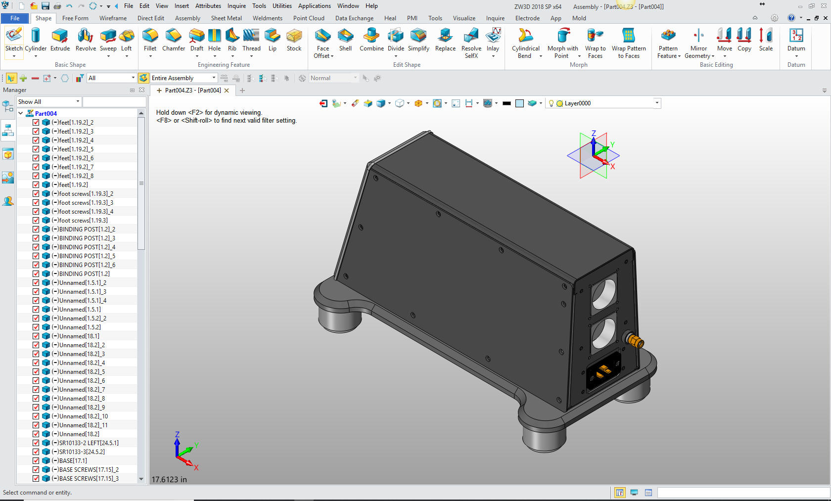
There are GD&T profile frames all over, there are faces not covered. There are flag notes that are not defined. Since this is not the authorizing document how did it get to my associate for programming. I seem to be the only one that finds this confusing. What is the purpose of this document? Inspection? The above company puts a bit more effort in trying to make the PMI a single viable engineering document. 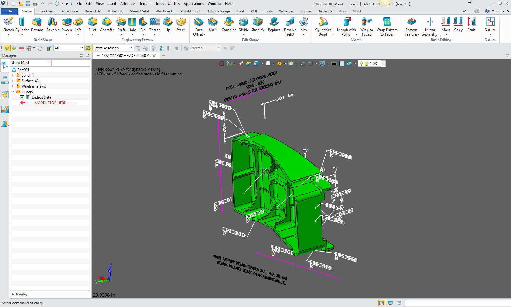 These PMIs are a horrible examples of engineering documents but can still be somewhat of a viable document for manufacturing and inspection. It leaves a lot to be desired, but they can work around the problems. The large companies can dictate to the suppliers and they jump through all of the hoops or else! If you are small company, the suppliers want the model and a fully defined AID as a PDF. PMI Assemblies IronCAD or ZW3D can read the native Pro/e clone file into one file. Imagine how much easier that would be to create the necessary assembly instructions. ZW3D even has an integrated AID allowing complete projects to be in one file. This solves much of the PDM problems for manufacturing.
Checking, Design Review, Manufacturing and Data Extraction! BOM was an architectural purchasing
document in the past. You can see how the PLM folks would get confused.
But a Parts List, never mind, do I really have to define it. LOL
"You cannot base your engineering deliverable If Oboe, others at Solidworks and probably the rest of the popular CAD vendors had professional engineers or draftsman on staff they would not come up with such silly unworkable solutions. This article was probably not even written by Oboe. The beginning of CAD they had engineering professionals on board. I remember being at Boeing in 1986 with list after list of enhancement requests for PC Based 3D CADKEY. If Boeing would have selected CADKEY over Catia, I am sure we all would not be in this PLM/MBE/MBD/PMI mess. The engineering world would have been on the PC over a decade before it arrived on the high-end systems at the turn of the century. CADKEY or Catia? Boeing’s Billion-Dollar 3D CAD Mistake! Today the major CAD vendors are driven by marketing. Huge corporations that serve the stockholders not the users. Their basic goal is to keep the user on board by any means. We really have to break the hold they have on our engineering. Boeing engineering is subservient to the InfoTechs and Dassault. We have to remember the AutoCAD was developed by architects. Computervision CADDS 4 and CADKEY were developed by those that were experienced mechanical engineering professionals. I know, I was proficient in these two early products. Pro/e? I am really not sure who developed it, I think it was programmers. Then Solidworks made 3D CAD even more removed from the realities of basic mechanical design and obviously continues today with many struggling with the limited constrained sketching, separate part, assembly and AID. 30 Years of 3D MCAD Incompatibility Is 3D CAD Productivity an Oxymoron? 3D Modeling Techniques Defined Sadly, Catia 5, NX, Solid Edge and Inventor were nothing but clones of this dated CAD paradigm. PLM showed up, ignorantly completely based on these systems, thereby locking the users into an inefficient system. IronCAD was released in 1998 and is superior to this stunted paradigm. Just think a minute, SpaceClaim came out exposing the productivity of direct edit, even though CADKEY and IronCAD had fully functional direct edit years before, IronCAD is the only truly integrated history/direct edit modeling system. But the industry is at the mercy of these 5 Pro/e (Creo) clones. It is like they are in a jail cell and the door is not locked and open to a new level of design freedom. IronCAD was completely unique with its drag and drop shape design, moving to a more intimate design relationship with how we truly make parts. Add a true single model environment and integrated direct edit, you have a system that increases productivity 10X. Five Functions that Increase 3D CAD Productivity!! ZW3D, while sketched based, offers primitive shape design that increases productivity. It has a multi-object environment and integrated AIDs that allow complete projects or sub-assemblies to reside in a single file. So as I have said many times
If you would like more information or to download ZW3D or IronCAD With 53 years of experience in engineering, 17 years in manual board design as a contract engineer, 35 years in 3D CAD sales, support, training and providing engineering services, I have a high level of understanding of today's 3D CAD engineering world. For many it is in chaos. If you are having problems or just interested in this subject please feel free to call and we can discuss them. There are so many simpler solutions available that will save you time and money.  Please visit our Viewpoints for more articles on our industry that may interest you. Please visit our Viewpoints for more articles on our industry that may interest you. See you online. Joe Brouwer 206-842-0360 |
TECH-NET ASSOCIATES | RENDERING OF THE MONTH | CAD•CAM SERVICES
HARDWARE | TECH TIPS | EMPLOYMENT | CONTACT