The
secret is:
They actual become the identifier of the manufactured part!
I have never seen so much attention paid to something that is so incredibly simple. I am so tired of seeing article after article written by some self proclaimed pundit sitting in some ivory tower that has an opinion on how we should do our engineering. These MSMEs, PHDs and InfoTech PLM Gurus have never checked out a part number, modeled an assembly, created the documentation or parts list, released it into the system, investigated problems, done a revision, etc and now are in charge of our engineering system? Virtually having no applicable knowledge. They have no professional experience on any 3D CAD system. Yet, they are telling those of us that work everyday designing functional parts how we should do it. Sadly, the industry leaders listen to them along with the major MCAD vendors, making our engineering world more convoluted and chaotic. Engineering Documentation - A Primer for the PLM Guru! PART NUMBERS are truly too simple to complicate. In engineering we are not defining a PART number we are defining drawing or document number. They do not become actual part numbers until the parts are made. But for this article we will use part numbers and know that there is always a drawing or document. Note: We have to define engineering documents: The Drawing, the 3D Model and the AID (Associated Information Document) delivered as a package and the obscure PMI. Why do we use part numbers? Because part names are so ambiguous. I always reference Boeing. How many supports, stringers, hat sections and frames do we have in an airplane? Can you imagine the confusion? 
So some bright fellow a century or so ago said: "Well, let’s just use unique numbers!” As a draftsman at Boeing and many other companies for that matter, I would check out a part number. There was no rhyme or reason. Just the next number. We may check out a block of numbers. Now these would not become important until the release of the drawing. 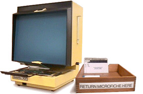 The
drawing was released into the system in the
beginning as a blue print and available at
blueprint counters. Soon, Boeing moved to
microfiche and we would go to the microfiche
center and look through boxes of cards. The
drawing was released into the system in the
beginning as a blue print and available at
blueprint counters. Soon, Boeing moved to
microfiche and we would go to the microfiche
center and look through boxes of cards.
How did they organize these blue prints and microfiche? Yes, very good, they did it in numerical order. But there was no significance of the number. You could have a secondary structure bracket and the next number would be a placard for payloads. Once in a while there would be part numbers especially defined for the group. When the drawing was released to Document Control where it was archived. This would put the basic requirements for setting this part into motion. It would be available for manufacturing planning who would send it to purchasing. They would review the drawing and send it to the appropriate manufacturing department or supplier to procure a quote resulting in an order for a number of parts. When I start a part numbering system for a company. I start with two letters that define the company. I also define each of the company products with unique set of top model numbers. But let’s not get wrapped up in numbers. What do the numbers represent in engineering? Yes, you have been paying attention: Drawings or Documents Now all drawings include in what assembly the part is used, what is called the "Used On". When you would get a rejection tag denoting a problem with the engineering from liaison, you would review the assemblies and trace down the parts you wanted to investigate. There are many common parts that come out of a bin and will not have a used on, mostly fasteners. We would look at the PL (Part List). If you see BOM (Bill of Materials) you were probably working with AutoCAD or a CAD program that came on the market after AutoCAD. It was basically an architectural package and that is what they call a Part List. Bizarre? Only to a few. Part List or BOM? We have to do a bit of an aside here so as to not fall in the trap of “Part numbers are all about engineering”. Of course, after the manufacturing of the part the part number now represents the actual parts themselves. We have special part mark instructions, print, stamp, bag and tag, etc. Yes we have to have part numbers to order the broken widget in our dish washers. After the drawing was used to make the blueprint and delivered to manufacturing it was put in a vault and may never be seen again. That is the funny part of part numbers. Once the project is done so is the part number as they relate to engineering. Hmm who has a bunch of active drawing numbers for a 57 Chevy??? So they are only important until they are delivered to manufacturing and put into a format, probably by planning, where they will never need the drawing again. When the project is complete you, will hopefully never see the drawing again.  Yes, I know if there is a problem or error with the part the drawing is checked out and revised. Lots of this goes on in engineering. Murphy is always hanging around causing problems.
There are a few drawings that handle many different configurations and were constantly being updated. But they were all assemblies. But most part drawings are put away never to be seen again. But once in a while parts can be modified for new products or a design modification. A small change here and a small change there. These are controlled by the dash (-) number. There may be many dash numbers involved with an inseparable assembly like a weldment or any other assembly that is permanently fastened (riveted or bonded) or have permanent fasteners like clinch nuts, studs, etc. A sheet metal assembly: 123456-1 Bracket Assy is made up of 123456-2 Bracket + cinch nuts + studs, etc. 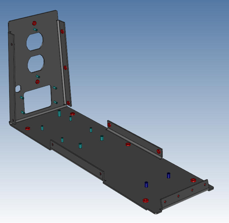 Okay, Okay we don’t do drawings any more. So now what do the part numbers represent? What do you mean, Joe, we don't do drawings? Of course we do drawings!!  The
times have been changing for awhile. In 1982 we, uh actually I, started working in 3D.
That is when Model Based Definition started.
Yes we were doing Model Based Definition
long before some Johnny come Lately thought of it in the late 1990's.
The 3D model was used only to create the
drawing in the beginning. The
times have been changing for awhile. In 1982 we, uh actually I, started working in 3D.
That is when Model Based Definition started.
Yes we were doing Model Based Definition
long before some Johnny come Lately thought of it in the late 1990's.
The 3D model was used only to create the
drawing in the beginning.
The 1980's - 3D CAD - The Beginning No, no, no!! It did not all start with PLM!!! We now had a 3D model and in those days until probably the late 1990’s an AID (Associated Information Document). These were drawing like documents, but were generated from the 3D model. No, we didn't do any drawing, just 3D modeling! EGAD!! The Death of the Drawing These AIDs (drawings) would be handled just like before, sent to document control, where they would be turned in to prints. We would send these AIDs (drawings) to manufacturing as a print. This was prior to CNC. As CNC showed up we would send the 3D wire frame with the printed AID (drawing) for what was called 2.5 axis machining. In the late 1980’s surfacing was well in place and we were now commonly providing the IGES 3D surface model for CNC including the printed AID (drawing) for reference to manufacturing. Things even got easier with when solid modeling showed up on the PC in 1995. Solid modeling and the AID made engineering design and documentation so simple! What? Simple? Just look at the mess today! The 1990's - 3D CAD/CAM Moves to the PC!! This, of course, went on until we could get the AID into the form of a PDF. This did not become popular until the late 1990’s. So now we were sending the 3D model in a native and/or neutral 3D format with the AID as a PDF in an "email". Something happened during the release of the PDF. Catia 5 came out for the PC. It came out with the concept of PLM. They probably looked at currently delivering the 3D model with the printed AID and came to the conclusion this was very costly. Of course, PDF was around the corner. Who knows when Catia made PDF a standard printer? Many companies bought an Adobe Acrobat, but soon free PDF printers started showing up. Most of the mid-range 3D CAD jumped on the PDF band wagon instantly, soon adding the ability to generate the regular PDF and later the 3D PDF directly from the program. The high end programs were always lagging. They had a bit of a more captured audience. The large manufacturing companies are stuck with these behemoths! The necessity to maintain a synchronized model and drawing and deliverery of the print became a horrible burden on the PLM system. This problem spawned the most idiotic and convoluted engineering deliverable to replace the AID (drawing). Enter MBD (Model Based Definition) and the PMI (Product Manufacturing Information) Why MBE/MBD/PMI Will FAIL Why MBE/MBD/PMI Will FAIL Part II 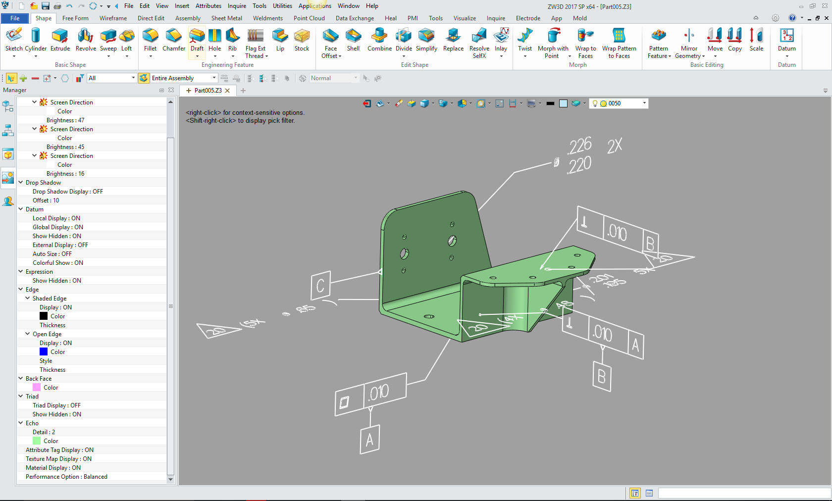 The above part as and AID  Good Gawd Joe, what the hell has this got to do with part numbers? Sadly, the PMI is a native file.
PMI vs AID Instead of sending out the 3D Model and an AID (with any level of detail) as a PDF to manufacturing that is in stone. The companies are dealing with handling the native CAD file and trying to deliver them to the supplier. These are actually emailed!!! Handling of a native CAD file is much different than delivering a dumb model. Boeing today sends out a Catia 5 native PMI file. You have to have a seat of the same version of Catia 5 or Enovia to read these files. Yes, there are 3rd party readers and translators that are available and have to be kept up to date to read latest version of Catia 5. Now, if you use those, you have to have a 3rd party validation program to assure the Catia 5 part is the same at the part you are machining. It is shocking no one sees the complications this causes and how it opens the door for Murphy to just stroll in! Compare and Validation Programs? Band-Aids for Self Inflicted Wounds! So Dassault has put Boeing and any other Catia 5 user in a place where the optimum is that all have the same version of Catia 5 to be compatible!!! Can you imagine a system devised by the Fox to protect the Chickens? Very clever those French!! I have worked with Boeing and Catia for over 30 years. Dassault is responsible for keeping Boeing one of the most ignorant and isolated manufacturing companies. Their lack of interoperability is beyond belief. Nothing makes me angrier than watching a company the size and reputation of Boeing an Icon in engineering standards so easily manipulated!!! This has caused a huge problem with those that need to import PMI. Here is a solution for importing Catia 5, NX, Creo and Solidworks files with PMI? Free PMI Importer? So again what has that got to do with the part number? Well, today the part is much more fluid than the simple yet complete in stone drawing. It sits in the PDM system not readily available to the outside world. All relationships are in the convoluted assembly mode of the 3D CAD program. In the past the blue print just sat there. No one worried about it. That is the state of Document Control today!! Part numbers are more than Part numbers! It is a convoluted PLM, PMI and MBD mess. Sadly the inmates are in charge of the asylum!! Luckily, smaller engineering/manufacturing companies are not in this mess. They can't afford the cost for this chaos.  This
is Easily Solved This
is Easily Solved We create a deliverable outside the CAD system in stone. In the past the optimum deliverable would be a 3D model and an AID. Yes the AID demands a bit of synchronization. But it depends on the level of detail. If it is a bunch of profile feature control frames, there is really not much to synchronize. Boeing is still sending out the PMI by email. You have to keep track of which supplier has been sent the file. The first tier dump it off to the second tier without all of the documentation. The PMI was supposed to stand alone, but Boeing has at least 2 other documents that travel with it. It is shocking that they do not realize that all of this confusion was included in just one blue print. SO THERE YOU GO!! PART NUMBERS ARE NOW VERY COMPLICATED!! ONE PART NUMBER IS MADE UP OF MULTIPLE DOCUMENTS!! 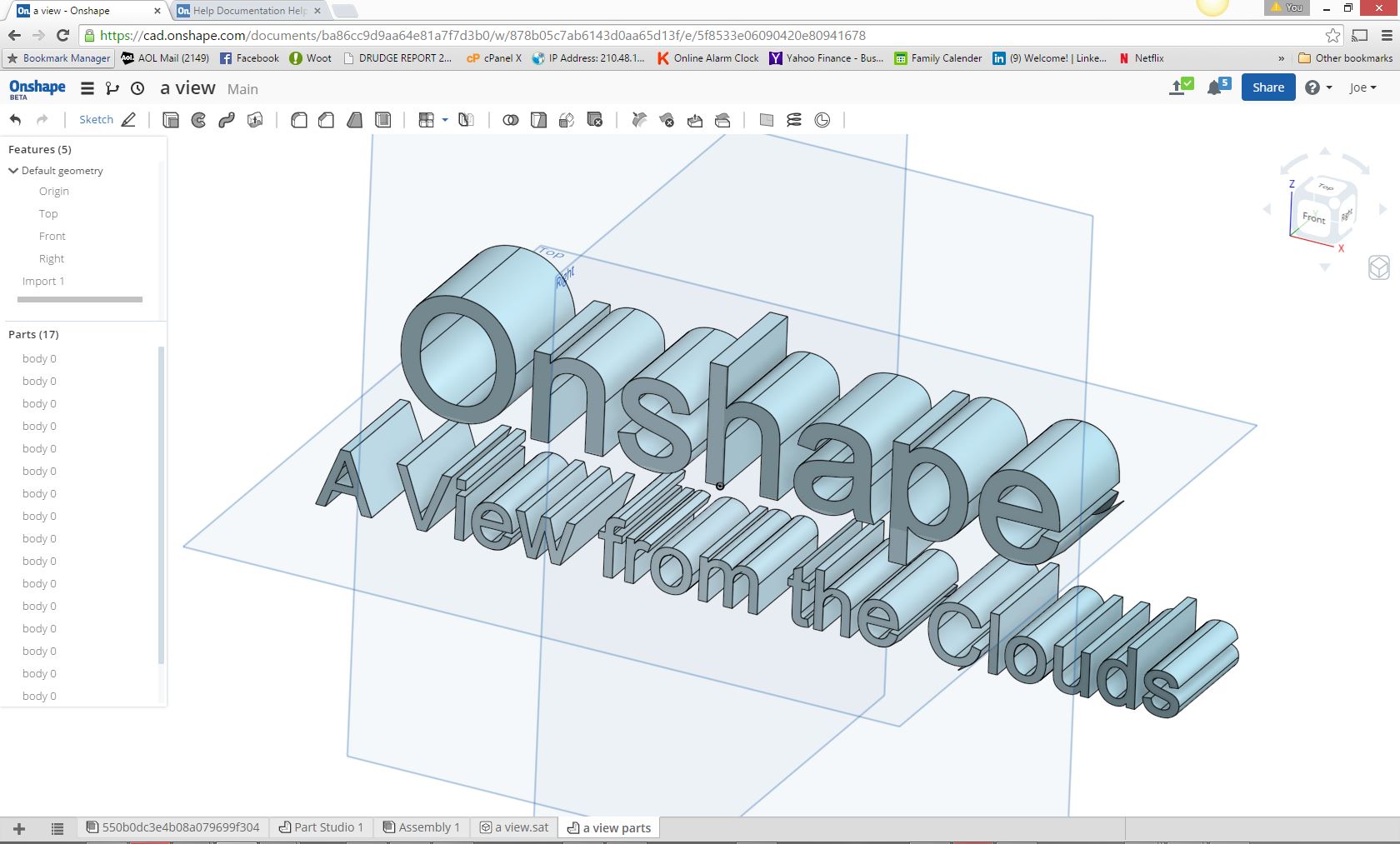 But
there is a new Document Control available. It actually goes
back to the Vault idea. It sits there waiting for anyone
that may need it. No email, no recording, no special
software, easily view-able!
Onshape
offers a great example of this process.
This concept allows you to up load any file to a document on the
cloud. You can import virtually any format and have the 3D model in
front of you. You may only need the native file since an Onshape
type document control solution would be able to
import most native files. Then you can export a variety of 3D
formats.
Now
this could be totally customize by the company. But
there is a new Document Control available. It actually goes
back to the Vault idea. It sits there waiting for anyone
that may need it. No email, no recording, no special
software, easily view-able!
Onshape
offers a great example of this process.
This concept allows you to up load any file to a document on the
cloud. You can import virtually any format and have the 3D model in
front of you. You may only need the native file since an Onshape
type document control solution would be able to
import most native files. Then you can export a variety of 3D
formats.
Now
this could be totally customize by the company.You can also have any amount of word, excel, other Microsoft office documents, images, pdf all available in one place. Standard Cloud Based Engineering Document Control Update 4-6-18 Now I will get back to the Part Number. With a well designed Cloud Based Document Controls System you can have the part number that includes any information or revision history. This is so simple. The 3D model and documentation is delivered to a Documentation Control group trained in handling this cloud based system in a standard format and are the only ones with modification privileges. Even the engineer would look here first for the released engineering information. This would give him/her the information to effectively look into the complicated native CAD PDM system. Some day we will have a better 3D CAD solution than the Pro/e paradigm of separate parts, assemblies and drawings. There are many products that have all in one file. 3D CAD Single Model Design Environment Again I State "PART NUMBERS are truly too simple to complicate". But then of course I am not a PLM expert with a MSME or PHD and a vested interest to make them complicated!! One More Problem How do we make sure that the 3d CAD model is the latest design version? When the 3D CAD file is released it has no identifier, beside the file name or the PMI information. Most suppliers will move the 3D model into their system. All identity is lost. We now have to make sure we keep track of the version of the model though the manufacturing process. Many times they have brought in the wrong part. They actually cannot tell the difference until inspection. This is a huge expense. It can be devastating across the board. The supplier may not be able to cover the costs, the customer may miss the very important schedule. This is relatively easy to Murphy proof! I call this the Embedded Title Block. It is truly shocking that this simple process has not been thought of! All CAD systems can modify the part to eliminate the part mark to have a clean machineable part. This is where a history based system has an edge on direct editing. You can just fill the engraving or trim the embossing . With direct editing only products you have to have two parts. But all direct only systems are single model environments and can have multibple parts coexist in the same design space. The Embedded Title Block! A PLM Solution! 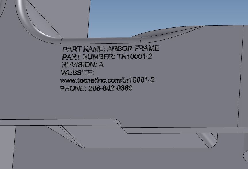 This should have been done years ago. Somewhere in the past the industry took a sacred oath. "The native 3D Model will not be modified" The lack of this simple process is costing the industry a fortune. Update 1-4-19 I am designing a new device and we needed a battery holder. We opted for a holder from Keystone Electronic. I downloaded the holder as a step file and this is what I found. It has been over a decade since I recommended this identification solution. This is not only a form of identification, but a marketing tool. Trust me, I am not genius, these are obvious solutions. 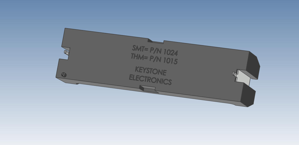 The ADCN (Advanced Drawing Change Notice) vs MBE This is incredibly stupid, most parts are modified by the CNC programmer to eliminate any features for the different steps in the program. Any supplier worth their salt will be using a functional direct edit 3D CAD system. I show a bit of this and more in this article: Checking, Design Review, Manufacturing and Data Extraction! The above article is one of four in a series. Leverage Your Engineering Data throughout your Organization! So you can see even though part numbers are very simple. Today's file management is much more open to Murphy's tricky fingers. P.S. A Real Design Experience. I just completed a job designing 3 separate and quite different electronic enclosures. The sheet metal parts were very complex. I personally create a complete AID (drawing) for each part. Creating complete AIDs (drawings) is basically done for a check on the design for errors and a second look at the design. Complete AIDs (drawings) are basically reference documents, easy to review. check and use for fast reference. I was pressed for time and every engineering person knows that Murphy loves tight schedules. The customer was making changes on the fly. I knew there may be errors. I was hoping the supplier would review the assemblies and note any errors. Most of the time I have time to get the job done. Printing out the AID (drawing) and marking them up (marking each dimension, call out, notes etc with yellow or red highlighter). But I just didn’t have the time. The suppliers gave me a call. How did they reference the parts and assemblies?? Yes, the part numbers I had all of the AIDs (drawings) for reference in a PDF format and all of the models in a STEP easily at my fingertips in folders, yes with part number and name, for review and to answer any of their questions. Drawing Requirements Manual (DRM) 11th Edition  The Drawing Requirements Manual contains instructions for the preparation of engineering drawings and models based on ASME Y14.100, ASME Y14.5M-1994, ASME Y14.41-2003, and many other standards and specifications for commercial applications, along with information on MIL-DTL-31000 for Department of Defense (DoD) and other government applications. If your are setting up an engineering department or if yours seems a bit lacking, I recommend the DRM (Drawing Requirements Manual). It includes part numbering standards and much, much more. This is my copy purchased in 1982! It has been invaluable to me. | ||||
|
TECH-NET Engineering Services!
If you are interested in adding professional hybrid modeling capabilities or looking for a new solution to increase your productivity, take some time to download a fully functional 30 day evaluation and play with these packages. Feel free to give me a call if you have any questions or would like an on-line presentation. For more information or to download IronCAD or ZW3D Joe Brouwer206-842-0360 |
TECH-NET ASSOCIATES | RENDERING OF THE MONTH | CAD•CAM SERVICES
HARDWARE | TECH TIPS | EMPLOYMENT | CONTACT